JAIST Repository
https://dspace.jaist.ac.jp/
Title 規則と責任モデリングを用いたソフトウェアの自動進
化
Author(s) 黄, 明仁
Citation
Issue Date 2008‑03
Type Thesis or Dissertation Text version author
URL http://hdl.handle.net/10119/4202 Rights
Description Supervisor:片山卓也, 情報科学研究科, 博士
Using a Rule-Base Approach and Responsibility Modeling for Automatic Software Evolution
by
Ming-Jen Huang
submitted to
Japan Advanced Institute of Science and Technology in partial fulfillment of the requirements
for the degree of Doctor of Philosophy
Supervisor: Professor Takuya Katayama
School of Information Science
Japan Advanced Institute of Science and Technology
March, 2008
Abstract
The purpose of this research work is to improve software evolution by managing the complex relationships between abstractions of different development stages. To this end, we propose and implement an automation approach for managing these relationships. This approach is based on the idea of capturing and reusing various types of relationships between abstractions.
A program realizes different types of high-level abstractions. As more functions are added to the program, the realization relationship between the program and the high-level abstractions conceived in the development process becomes more complex. To evolve a program without degrading its quality, managing this complexity is the key point. To this end, in this research work we propose a new development approach, which is based on three theories. (1) First, to eliminate the gap between different worlds in software development process, we use a single-type paradigm for modeling abstractions that are created in different worlds but are also related at the same time. (2) Second, to simplify the evolution of the relationships among abstractions, we propose directly creating a program by reusing previously considered development knowledge of relationships among abstractions. More specifically, a program is constructed from the modules of the relationships of abstractions which are conceived in the development process and are recorded by the single-type paradigm in (1). (3) Third, we propose using rule engine for implementing a tool for automating software evolution by reusing and composing the modules mentioned in (2). The automation provided by this approach is for the following three evolution scenarios: (a) when the given business processes are evolving, (2) when the realization-development knowledge is evolving, and (3) when a different implementation technology is adopted. To evaluate the effectiveness of the proposing approach, a case study with three software systems is conducted.
In this dissertation, we describe the construction of the proposing approach. In the first step, the basic framework is constructed. This framework helps developers to capture development knowledge they acquire in the development process. It includes a modeling language and a set of graphical notations. We then describe how the modules of relationships among abstractions can be used to construct/evolve a program. In the second step, the
implementation for automated program construction/evolution is developed. This implementation provides the features of development knowledge modeling and program construction/evolution automation. Finally, a case study is conducted. The results of the case study provide the support for the proposing three theories for software evolution.
The evaluation results show that a single-type paradigm by using responsibility can be effectively used to describe the relationships of abstractions within the four worlds. The modularization of development knowledge can effectively capture how developers design realization of abstractions of different worlds. Finally, a rule engine encodes the development knowledge for inferring the development of system responsibilities, object responsibilities, and program responsibilities.
Acknowledgments
This research work is supported by many people. I would like to thank to Professor Takuya Katayama for his kindly guidance, encouragement, and support in many different forms. I am very lucky to have him to be the supervisor of my master and PhD study.
I would like to thank to all committee members: Professor Motoshi Saeki, Professor Koichiro Ochimizu, Professor Tomoji Kishi, Associate Professor Masato Suzuki, and Associate Professor Toshiaki Aoki. Your comments are invaluable to me.
I would like to thank to my colleagues, especially Assistant Professor Kenrou Yatake, Dr. Rami Yared, Dr. Samia Souissi, Mr. Nǎixué Xióng, and Ms Yàn Yáng.
I would like to thank to Professor Leon J. Osterweil at University of Massachusetts Amherst and every people I met while I was there. This was the most exciting moment I had so far.
I would like to thank to my family in Taiwan. Especially, I would like to thank to Mom for making me love to read and to learn from my childhood. I would also like to thank to my mother-in-law for her kindly help while I were finishing this dissertation. I would like to thank Mr. and Mrs. Hamada in Nagoya for treating me like your family member.
Last but not least, I would like to thank to my wife Lisa, our lovely son Wei-Wei, and our coming baby. You keep me moving forward.
Contents
Abstract...i
Acknowledgments... iii
Contents ...iv
List of Figures ... viii
List of Tables ...xi
Chapter 1 Introduction ...1
1.1 Problem...1
1.1.1 Background...1
1.1.2 Problems and Gap ...2
1.2 Overview of the solution...3
1.2.1 Basic idea of the solution...4
1.2.2 Fundamental theories of the solution...5
1.2.3 Scope of the solution...7
1.2.4 Construction of the solution...8
1.2.5 Case Study of the solution ...9
1.3 Organization of the dissertation...12
Chapter 2 Related Work...14
2.1 Model-driven development...15
2.2 Abstraction decomposition ...17
2.3 Traceability management...18
Chapter 3 Basic Framework...19
3.1 Responsibility modeling for realization-development knowledge ...19
3.2 Essential modeling elements...21
3.2.1 ModelingElement...22
3.2.2 Responsibility ...23
3.2.3 Task...23
3.2.4 Actor ...24
3.2.5 Document...24
3.3 Parameterized Realization unit (PRU)...24
3.3.1 PRU...26
3.3.2 Realization ...27
3.3.3 Collaboration...27
3.3.4 Constraints ...28
3.4 Management of modeling elements ...30
3.4.1 Domain...31
3.4.2 World ...31
3.4.3 RSDProject ...31
3.4.4 BusinessProcess ...31
3.5 Modeling Process...31
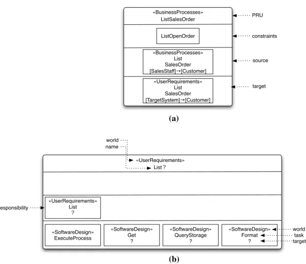
3.6 Graphical notations ...34
3.6.1 PRU...34
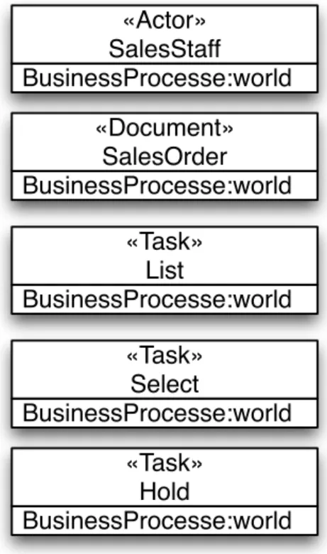
3.6.2 Actor, Document, and Task ...35
3.7 Stereotyping ...36
3.8 Summary...38
Chapter 4 Reusing realization-development knowledge ...39
4.1 Approach overview...39
4.2 Constructing a program by PRUs ...41
4.3 Evolving a program by PRUs ...44
4.4 Automating the reusing of development knowledge ...48
4.4.1 Parameterized realization unit for knowledge reusing...49
4.4.2 Matching scheme of PRU selection...52
4.5 Why single-type paradigm modeling for abstraction and knowledge representation....52
4.6 Summary...54
Chapter 5 Rule-based implementation...55
5.1 Features of RSDTools...55
5.2 Structure of RSDTools...56
5.3 Automatic Jess code generation...58
5.3.1 Structure of modeling elements in Jess templates ...58
5.3.2 Example of Jess facts ...60
5.3.3 Jess rules ...65
5.4 Automation of program construction/evolution...67
5.4.1 RSD program construction ...68
5.4.2 RSD program evolution ...69
5.4.3 Business-processes evolution...70
5.4.4 Realization-development knowledge evolution...73
5.4.5 Technology evolution...76
5.4.6 Version control of RSD ...76
5.5 Summary...78
Chapter 6 Case Study...79
6.1 Case study overview ...79
6.1.1 Business-MS ...79
6.1.2 Medical-SS...83
6.1.3 Shopping-WS...84
6.2 Evaluation ...85
6.3 Discussion...92
6.4 Summary...99
Chapter 7 Summary and Future Work ...100
7.1 To design the basic framework ...101
7.2 To implement the tool for supporting the automated construction/evolution of a
program...102
7.3 To develop a case study with three systems ...103
7.4 Contribution ...103
7.5 Future Work ...104
References...106
Publications...112
Appendix A: Use Cases ...113
A.1 Business-MS ...113
A.2 Medical-SS...114
A.3 Shopping-WS...114
Appendix B: Example output results of Jess...116
Appendix C: Examples of PRU Data ...120
C.1 PRUs for business-processes realization ...120
C.2 PRUs for user-requirements realization...121
C.3 PRUs for software-design realization ...123
List of Figures
Figure 1-1. Three fundamental theories for Evolution Automation ...7
Figure 1-2. Conceptual structure of the construction process...9
Figure 1-3. Creation order of the three systems...11
Figure 3-1. The cycle of four stages ...20
Figure 3-2. Metamodel of responsibility ...22
Figure 3-3. Metamodel of PRU ...25
Figure 3-4. Metamodel of domain. ...30
Figure 3-5. Metamodel of RSDProject ...30
Figure 3-6. Domain and application modeling ...33
Figure 3-7. An example of graphical notation of PRU...35
Figure 3-8. An example graphical notation for actor, document, and task...36
Figure 4-1. Software evolution helps by PRUs ...41
Figure 4-2 Creation of a RSD Program by using PRU. Intermediate abstractions are instantiated by using PRUs. ...42
Figure 4-3. The details of the problem-solution process ...43
Figure 4-4. Evolution of a RSD program by using PRU ...45
Figure 4-5. Realization-development knowledge evolution...46
Figure 4-6. The evolution of two realizations shared one PRU...48
Figure 5-1. High-level structure of RSDTools ...57
Figure 5-2. deftemplate of Actor...59
Figure 5-3. deftemplate of Document...59
Figure 5-4. deftemplate of BusinessProcoess...59
Figure 5-5. deftemplate of Responsibility...60
Figure 5-6. deftemplate of PRU...60
Figure 5-7. deftemplate of Collaboration...60
Figure 5-8. Example of Actor’s Jess facts. ...61
Figure 5-9. Example of Document’s Jess facts. ...62
Figure 5-10. Example of BusinessProcess’s Jess facts. ...62
Figure 5-11. Example of business-processes responsibility’s Jess facts. ...64
Figure 5-12. Example of business-processes PRU’s Jess facts. ...65
Figure 5-13. Example of Jess rules for selecting and instantiation abstractions. ...67
Figure 5-14. Jess rules for retract just-satisfied responsibility. ...67
Figure 5-15. The internal work of EAC when constructing the example RSD program...68
Figure 5-16. The internal work of EAC when adding new business-processes responsibility. ...71
Figure 5-17. The internal work of EAC when removing business-processes responsibility...73
Figure 5-18. The internal work of EAC when evolving the realization-development knowledge...75
Figure 5-19. Flatten structure of single evolution scenario. ...77
Figure 5-20. 2D structure of multiple development process...77
Figure 5-21. Flatten structure of mixed evolution scenarios ...78
Figure 6-1. Conceptual flow of Business-MS for Sales document processing...80
Figure 6-2. Conceptual flow of Business-MS for procurement document processing...81
Figure 6-3. Conceptual flow of Business-MS for inventory document processing...82
Figure 6-4. Conceptual flow of Medical-SS...84
Figure 6-5. Conceptual flow of Shopping-WS. ...85
Figure 6-6. Required and new PRUs of the JSP system of Business-MS. ...93
Figure 6-7. Reused ratios of the JSP system of Business-MS. ...94
Figure 6-8. Required and new PRUs of the JSP system of Medical-SS...95
Figure 6-9. Reused ratios of the JSP system of Medical-MS. ...96
Figure 6-10. Required and new PRUs of the JBoss Seam system of Shopping-WS...97
Figure 6-11. Reused ratios of the JBoss Seam system of Business-MS...98 Figure 6-12. Reused ratios of the JBoss Seam systems of both Business-MS and Medical-SS.
...98
List of Tables
Table 1-1. Implementation technology of the evaluating systems. ...12
Table 3-1. Modeling scenarios of meta-constructs creation ...33
Table 4-1. Example of business-processes responsibilities. ...49
Table 4-2. Example of user-requirements responsibilities ...49
Table 4-3. Example of a parameterized realization relationship ...50
Table 4-4. Matching scheme of PRUs ...52
Table 6-1. Document list of Business-MS. All of these three volumes are provided as companion documents. ...82
Table 6-2. Numbers of required and new PRUs for each business processes for the JSP system of Business-MS...87
Table 6-3. Numbers of required and new PRUs for each business processes for the JSP system of Medical-SS ...87
Table 6-4. Numbers of required and new PRUs for each business processes for the JBoss Seam system of Shopping-WS...89
Table 6-5. Numbers of required and new PRUs for each business processes for the JBoss Seam system of Business-MS...90
Table 6-6. Numbers of required and new PRUs for each business processes for the JBoss Seam system of Medical-SS ...91
Chapter 1 Introduction
1.1 Problem
1.1.1 Background
A business software system is usually developed as a staged-process. Among other activities, in each stage developers conceived abstractions to realize abstractions created in a previous stage. For example, for developing a business system, developers firstly define business tasks and business actors in a business process. From here, user requirements are defined to realize these business activities, software design is created to realize user requirements, and program is pondered to realize software design. Finally, a program that realizes all these high-level abstractions is implemented. In this process, there are many relationships designed by developers. We can see realization of abstractions between two stages, collaboration of entities within a stage, or a constraint on the realization or collaboration. As customers request more functions, a program is more bounded to abstractions conceived in the process. It becomes harder to manage these relationships to evolve software. The overall result is a quality-degraded program [1].
Previous research work focuses on different aspects of this problem. One concept that is considered an effective approach for preventing a quality-degraded program is reusing.
This concept is closely related to modularization. In software engineering, we have various modularization paradigms for creating implementation-based artifacts, such as functions in function oriented programming, and objects in object-oriented programming (OOP). These paradigms eliminate repetition when creating a program and help developers focus on a small area of development without being bothered by other unrelated issues. The construction repetition can be minimized because a function or a class (a class is the definition of an object) can be reused many times to realize high-level abstractions. Another similar concept is component-based reusing, such as COM on Windows [2] or EJB on Java [3]. Different from the reusing paradigms introduced so far, which are at source-level and
for single-platform reusing, the component-based reusing is binary-level, single/multi- platform reusing.
Even the repetition of implementation can be reduced by the above approach, but one kind of repetition that is rarely been considered is the abstraction realization between different development stages. This kind of repletion can be observed in a development project. It can be easily observed that some similar implementation modules are always created for realizing some similar high-level abstractions. More specifically, certain functions, objects, or a fragment of code are reused collectively and repeatedly for realizing some similar high-level abstractions. Developers possibly only customize an existing solution to realize high-level abstractions rather than creating a new solution every time.
For example, some similar business tasks are always realized by using similar object design, and constructed in similar ways. However, current development methodologies or programming paradigms do not provide formal support for reusing these customizable solutions. Productivity provided by such a support is overlooked. The reusing mechanism only focuses on the expected behavior provided by the programming modules, rather than the high-level purpose of the modules construction. In the current ever-changing business environment, design knowledge, and implementation technology, the management of these relationships become more complex and more important.
In the following sections, the problem and the gap that motivates this research work are discussed in details. The solution we propose in this research work is also introduced.
1.1.2 Problems and Gap
There are two problems when overlooking abstraction relationships. First, without such information, developers are hard to answer such a simple question: “could you please tell me which part in a program implements this requirement?” It is also hard to guarantee that high-level and low-level abstraction is consistently constructed when evolution happens. Second, we have to reinvent (or forget) a good design of abstraction relationships to solve some similar problems.
Although the abstraction relationship plays such an important role in software development, the truth is that current technologies and practices usually focus on proposing better approaches from a diagonal direction. That is, developers can easily add or modify a method or an object to a program; however they lack an explicit support for relating this newly added or modified part with other part in the program. Besides, they lack the support of comprehending the relationships between the change of implementation-level artifacts and high-level abstraction, such as requirements and software design.
A different strategy that fills this gap should be proposed. This approach should value the importance of the relationships among abstractions. By this strategy, developers can model the relationships conceived for different systems. By this model, developers can focus on designing a small area of these relationships each time. Each small area of this model is encapsulated as an independent unit. A solution for any given problem in the development process can be created by combining these reusable units. The construction of a program is simply the assembly of the units. This unit does not only provide as a reusable knowledge for constructing a program, but also the information for comprehending the design of a program.
Therefore, in this research work, a development approach that focuses on the modularization of abstractions is proposed. In this dissertation, we describe how this idea forms an approach for software evolution and how the implementation of this approach is applied to the automation of program construction/evolution.
1.2 Overview of the solution
The problems and the gap motivate us to propose a new approach for software evolution.
This approach, as we mentioned before, values the importance of the abstraction relationships. By this approach, a program is constructed and evolved by the application and combination of reusable knowledge. Eventually, an implementation of this approach is created for automating program construction/evolution.
1.2.1 Basic idea of the solution
A program can be considered as a big solution to a big problem of the real world. A relationship between high-level and low-level abstractions of this program can be considered as a pair of one small problem and one small solution, which may belong to two different development stages. We use the term, worlds, to represent these stages. It is because a stage usually has abstractions that are specified to that stage which form as a world. The problem of high-level abstractions in one world is solved, or realized, by the solution of low-level abstractions in another world. Practically, there are patterns when defining the realization between any two worlds. Developers reuse or customize exiting relationship to create a solution to solve similar problems. This phenomenon is especially true to the business domain. In business domain, we can observe
z Highly repetitive business processes. There are many similar business tasks in different business processes.
z Structural system design. Developers usually use construct a system in a similar way, for example, the application of three-layered architecture: presentation layer, business- logic layer, and integration layer.
z Abundant object-design solution. There are many reusable solutions been considered for the object-design problems.
Based on these observations, we make an assumption that in the business domain it is possible to derive a pattern from a collection of similar abstraction relationships. This pattern becomes an effective mechanism for creating other concrete relationship when constructing/evolving a program. This proposing approach is constructed on this assumption. By considering a program as a solution for the problem of business processes, this program can be constructed/evolved by consulting these patterns. Moreover, when the problems, solutions, and the realization relationships connecting them are encoded into a computable form, a program can be automatically constructed or evolved.
Each pattern, which is called a parameterized realization unit (PRU) in this approach, is a reusable asset for constructing/evolving a program. PRUs are used to stored humans’
knowledge about abstraction realization. A PRU represents a piece of abstraction realization-development knowledge between two worlds. It also contains other relationships, i.e. collaboration and constraints, that are related to this realization. It works as a template which can be instantiated for creating a concrete realization relationship, where each instantiated instance provides a “small” solution to a “small” problem. From this instance, developers know what abstractions (solution) should be created in one world, when they encounter some abstractions (problem) in another world. The collection of these instances relates all abstractions conceived in the development process of a program. The evolution of a program becomes the addition, removal, or replacement of the instances of these patterns. When developers learn more about the business domain, they can construct/evolve a program more productive by only reusing the PRUs.
The problem and the solution pair effectively encode two types of information. The first type is the condition of a solution. That is, when one solution that represents what abstractions should be created when one problem is encountered. Therefore, the first type of information tells developers when they should reuse a unit. The second type of information tells developers what abstractions they should create when this unit is reused.
1.2.2 Fundamental theories of the solution
Before proposing this approach and implementing it as a tool for the evolution automation, there are some fundamental issues that should be solved.
(1) First, the current multi-paradigm practice for software development may hamper the creation of a PRU. Currently, different types of paradigms or concepts are used for abstraction description. For example, while developers use a process oriented language to describe a business process, they use different concepts, such as software objects for realizing this business process. (2) Second, a pattern, i.e. a PRU helps human developers record and reuse their development knowledge about abstraction realization for constructing/evolving a program. This unit also helps machines for the same purpose with a
step further beyond the manual way by humans. By encoding PRUs, and the problems and solutions involving in the units, a machine knows how to construct/evolve a program automatically. Therefore, (3) the third issue is to find an efficient platform for implementing our idea. We need a platform that helps developers directly encode their development knowledge in a computable form. This platform should also help us create the actions for reusing the realization development knowledge.
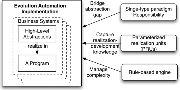
The answers to the three issues are three fundamental theories, which are illustrated in Figure 1-1. (1) First, to eliminate the gap between different worlds, we propose responsibility modeling, a modeling approach based on single-type paradigm, responsibilities. Responsibility in our approach is not only used for designing what work should be done by software object [4][5], but also for modeling the tasks that should be performed by entities of different worlds and different types of information that should be processed by the entities. Most importantly, responsibilities provide a good abstraction for describing the relationships among different entities. (2) Second, to simplify to manage the abstraction relationships of a program, we propose capturing the connections among abstraction as reusable and composable knowledge by the paradigm of responsibility. By this theory, these connections become the first-class citizen for constructing and evolving a program. (3) Third, to automate the reusing and composing of knowledge, we propose using rule-based engine by encoding the realization-development knowledge. A tool implementing on rule-based engine can automatically infer a program as the solution to the problem of the given business processes.
The combination of the three proposing theories is a development approach, called Responsibility-Steering Development (RSD for short), will fill the gap we mentioned in Section 1.1.2. The implementation of this approach is tool, called RSDTools, for automating program construction/evolution.
Singe-type paradigm Responsibility
Parameterized realization units
(PRUs) Evolution Automation
Implementation
Rule-based engine Bridge
abstraction gap
Capture realization- development
knowledge
Manage complexity High-Level
Abstractions
A Program Business Systems
realize in
Figure 1-1. Three fundamental theories for Evolution Automation 1.2.3 Scope of the solution
The scope of our solution can be discussed from two aspects:
First, its application domain is limited to business domain. The proposing approach focuses on the modeling of the realization of humans’ responsibilities in a business by a program. The automation support only applies to the evolution that happens between humans’ responsibilities in a business and the program that automates the performing of these responsibilities.
Second, by using RSD, the development of a business system can be dynamically satisfied by using the collection of realization-development knowledge. Dynamically satisfaction of software development by using realization-development knowledge represents that developers can freely add new development knowledge to realize any unrealized business responsibility without invalidating current realization.
This capability is limited to the following three evolution scenarios: business- processes evolution, realization-development knowledge evolution, and technology evolution.
z Business-processes evolution: Assuming there is a program, which has been constructed for realizing some business responsibilities by using a collection of development knowledge, this program can be automatically evolved when the given business responsibilities are added, modified, or removed.
z Realization-development knowledge evolution: Assuming there is a program, which has been constructed for realizing some business responsibilities by using a collection of development knowledge, this program can be automatically evolved when the collection of development knowledge is added, modified, or removed.
z Technology evolution: Assuming there is a program, which has been constructed for realizing some business responsibilities by using a collection of development knowledge; this program is automatically evolved when the underlying implementation technology is changed.
1.2.4 Construction of the solution
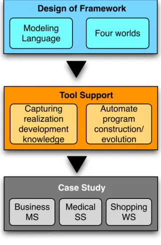
We construct RSD in three steps (see Figure 1-2).
First, the basic framework of RSD is designed. This framework is used to help developers to capture realization-development knowledge they acquire in the development process. It includes a modeling language for capturing the realization-development knowledge. It also includes the definition of four connected worlds, where each world corresponds to one stage and provides a distinct context for creating abstractions. Finally, it defines the process of using many small pieces of realization-development knowledge for constructing/evolving a program.
Second, a tool for supporting the automated construction/evolution of a program is developed. This tool is constructed based on the idea and the fundamental theories mentioned before. Developers can use it to capture realization-development knowledge and to model business processes by using the modeling language designed in the first step. It
automates the construction/evolution of a program under the three scenarios described in Section 1.2.3.
Finally, a case study which includes three business systems is developed. We use this case study to evaluate the effectiveness of the proposing approach. More details about these three systems are given in Section 1.2.5.
Design of Framework
Modeling
Language Four worlds
Tool Support Capturing
realization development
knowledge
Automate program construction/
evolution
Case Study Business
MS
Medical SS
Shopping WS
Figure 1-2. Conceptual structure of the construction process 1.2.5 Case Study of the solution
A case study for evaluating the effectiveness of the proposing approach is conducted. This case study includes the development of three software systems, a business-process management system (called Business-MS), a medical supporting system (called Medical-
SS), and shopping-mall-on-web system (called Shopping-WS). The first system has been commercially deployed. The second system is a research based on the paper [6]. The third system will be commercially deployed in future. These three systems verify the claim that made in Section 1.2.3. This claim is that in the three evolution scenarios, the development of a business software system can be dynamically satisfied by the collection of realization- development knowledge. Dynamically satisfaction of software development by using realization-development knowledge represents that developers can freely add new development knowledge to realize any unrealized business responsibility without invalidating current realization under the three evolution scenarios mentioned above.
Therefore, this case study is intended to verify the business-process evolution and realization-development knowledge. The technology evolution is verified by using development technologies to create different variations from the same set of business- process responsibilities.
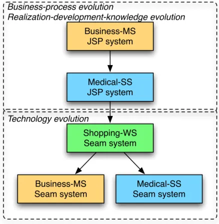
To simulate different evolution scenarios, the same set of requirements of the three systems are implemented by using different technologies. The first (Business-MS) and the second (Medical-SS) systems have two variations. One is implemented by using JavaServer Pages (JSP) [7] and JavaBeans [8][9]. JSP is for information visualization and JavaBeans is for information processing logic. The other is implemented by using JBoss Seam [10][11], which is a new programming model for creating Java enterprise system. However, the third system (Shopping-WS) is only implemented by using JBoss Seam.
Business-MS JSP system
Medical-SS JSP system
Shopping-WS Seam system
Business-MS Seam system
Medical-SS Seam system Business-process evolution
Realization-development-knowledge evolution
Technology evolution
Figure 1-3. Creation order of the three systems
The creation order of these three systems implies the evolution process, which is shown in Figure 1-3. The creations of the first variation of Business-MS and Medical-SS illustrate business-process evolution and realization-development-knowledge evolution.
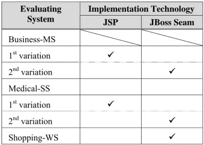
The creations of Shopping-WS and the second variation of Business-MS and Medical-SS illustrate technology evolution. We use the PRUs created for the third system to develop the second variation of Business-MS and Medical-SS. Table 1-1 summaries the implementation technologies used by each system.
Table 1-1. Implementation technology of the evaluating systems.
Implementation Technology Evaluating
System JSP JBoss Seam
Business-MS 1st variation 9
2nd variation 9
Medical-SS
1st variation 9
2nd variation 9
Shopping-WS 9
1.3 Organization of the dissertation
This paper is organized as follows:
In Chapter 1, we describe research topic. We state the problem and gap that motivates us to propose the approach. We describe the proposing approach for software evolution by explaining its basic idea and fundamental theories. We also state the intended evolution scenarios of the proposing approach. Finally, the construction and the evaluation of this approach are summarized.
In Chapter 2, we review some previous work that is related to our research topic.
In Chapter 3, we describe the basic framework that helps developers to capture realization-development knowledge they acquire in the development process. It includes a modeling language for capturing realization-development knowledge. A supplementary set of graphical notations is also provided for visualizing the captured development knowledge.
In Chapter 4, we describe how program construction/evolution is achieved by reusing the realization-development knowledge. The reuse is centered about an idea called parameterized realization unit (PRU), which is a customizable realization relationship.
PRUs are used to store humans’ knowledge for reusing. We show that how a program constructed by using PRUs is also capable of to be evolved by the same mechanism of PRUs.
In Chapter 5, we describe the implementation of the supporting tool. We show the features the tool provides, the structure the tool is constructed, and the internal work it performs for the automation of program construction/evolution. This tool does not only provide the modeling of realization development-knowledge, but also has a rule-based engine integrated for program construction/evolution automation. We show how rules are implemented for this automation.
In Chapter 6, we describe the evaluation of the proposing approach. We show the statistics of the evaluating results, which characterizes the novelty of this approach.
In Chapter 7, we summarize this dissertation and future work.
Chapter 2 Related Work
Software evolution becomes an emerging area of research work. Lehman and Ramil [12]
discussed the definition of software evolution. From their definition, we can separate the study of software evolution into the means and the observation. The former concerns how and the later concerns when and what. There are fewer research work about the later [13, 14, 15, 16, 17, 18, 19, 20, 21]. The topics of the former are various. We have program evolution by refactoring [22, 23, 24] for source code evolution. Another important area is higher-level abstraction evolution, which concerns more on requirements or design aspect of a program [25, 26, 27, 28]. There is also some research work about external environment (e.g. business, work, etc.) evolution [29. 30].
Our research work limits its applicability the evolution of higher-level abstractions and to the business domain. One important characteristic of the software systems of this domain is that they concern the real-world business activities. As suggested by Lehman and Fernandez-Ramil [31], the systems for the business domain, which were also called E-type systems by their work, have an important characteristic that their behavior must satisfy the operational context. That is, they must exhibit the behavior defined in terms of computer abstraction that satisfies user requirements defined in terms of the real-world abstraction.
Synchronizing the two worlds reveals one of the challenges in the study of software evolution [32].
This is such a complex issue that is approached by previous work from different aspects. Since it is not possible to review all of the aspects in this dissertation, we limit the review of previous work to those that are possible to solve the problem of dis-synchronized between real-world and computer-world abstractions. The following research aspects are discussed.
2.1 Model-driven development
The first is an attempt that tries to use a set of universal rules for mapping between the real- world and the computer world. This set of universal rules will transform any given real- world problem to any computer-world solution. This approach is usually called model- driven development (MDD), since the problem domain, the solution domain, and the mapping rules are defined under a metamodel [33][34][35]. A metamodel is a model for defining other models, which can be used to define the concepts for describing the facts of the real-world (i.e. the problem domain), the computer-world (i.e. the solution domain), and the mapping between these two worlds. Since both worlds are defined in terms of the same modeling paradigm, the mapping rules can be easily created. One example that has been discussed frequently is MDA (model-driven architecture) [36].
We use MDA to discuss the general approach adopted by MDD. The single most important element of MDD is the transformation definition between models. In MDA, there is a standardized metamodel called MOF for defining transformation. Consequently, the source and the target of transformation is also defined in this meteamodel. The significance of MDA transformation is that abstractions of the real-world problem should be separated by the computer-world. That is, the modeling of the real-world problem has no concerns of the solution of the problem. The solution is derived i by the transformation definition. It is a very important characteristic because such the separation cannot be easily achieved by other traditional approach. The metamodel MOF define the scope of modeling different worlds. Under MDA’s terminology, the source of transformation is called PIM (platform- independent model), and the target of transformation is called PSM (platform-specific model). A PIM is always impendent from some form of abstractions. For example, a model for describing business processes is independent from how a system is automated by a software system. Therefore, a model that describes business processes is a PIM and the model that describes the automation of business processes by a software system is a PSM.
The meaning of this approach to the synchronization of the two worlds under the context of software evolution is apparently. Since there is a transformation definition that is
universally capable to transform between any two models which belong to one pair of two specific domains, the solution for a continually evolving problem domain can always be inferred.
Since the implementation of model transformation, i.e. the actual logic that use the transformation definition to create the target model from the source model, is not specified by MDA, research work and industrial products based on MDA’s standards or concepts are abundant, and usually has different focuses. At the same time, it is also hard to clearly distinguish an approach that adheres to MDA speciation and those that are merely based on the concept of model-driven development. As Sendall and Kozaczynski [37] summarize the various mechanisms into there are three types, which are direct model manipulation, intermediate representation, and transformation language support. Examples of the first type are some commercial tools such as Rational XDE, which uses a set of VB API for model manipulation. Action language [38] also falls into this category. Examples of the second type include XML-based representations such as XMI [39].
Some work are reviewed below. Since this dissertation is not on the topic of MDA but about software evolution in general, the work reviewed below are not limited to MDA- compliant.
Arlow et. al. [40] describes a transformation approach called archetype patterns that each archetype pattern specifies a mapping rule between the problem (analysis, design) and the solution (design) domains. An archetype pattern may have various variations for fitting in different context. They describe their approach can be defined in MDA’s standards and automated by tools. Wegmann et. al. [41] proposes combining three elements, MDA, enterprise architecture (EA), and the living system theory (LST) to integrate different models in a hierarchical structure that includes business, organization, design, and implementation concepts. Each layer in the hierarchical structure consists of models and mappings are defined between layers. The significance of their work is incorporating the three aspects, technology (MDA’s standards), business (EA), and information (LST’s integration of layers) to provide a sound solution for model transformation.
2.2 Abstraction decomposition
The second approach is an attempt that tries to decompose the real-world problem into small pieces and derives the solution from the decomposed problems. Decomposition is also called divide and conquers, which is a word originated from ancient Latin saying, for referring a strategy by breaking big problem into small ones in order to manage one small problem at a time. This is a very general approach that has long been used to solve problems of many different domains, from mathematical proving [42] to computer hardware design [43]. The meaning of this approach to software evolution is the ease of evolution spotting. Evolution spotting is an action of finding related parts that should be changed as well when one specific part is changing (or changed). Since the problem, the solution, and the mapping between them are decomposed into smaller parts, it is easier to look up all parts that should be changed. However, it is important to choose abstractions for decomposition when the problem and the solution are at different worlds. This is the characteristic of E-type systems. We need a good abstraction (or abstractions) that can express the real-world and the computer world.
Two works that apply the idea of divide and conquer is reviewed here, one is Multi- Dimensional Separation of Concerns (MDSC) [44] and the other is Feature-Oriented Programming (FOP) [45]. These have two distinct choices of abstractions for decomposition. In MDSC, Clarke, Harrison, Ossher, and Tarr recognize the necessary of separating different types of concerns (features, business rules, objects etc) within programs.
After these concerns are identified, programs can be composed and evolved as concerns change. They propose using different paradigms, where each paradigm is suitable for describing a single type of concerns. Conversely, FOP uses the one-single abstraction, called feature, for decomposing and composing different types of concerns. In FOP, software evolution of a program family can be incrementally synthesized [45] and evolved [46] from small features. Although they have different choices of abstraction representation, generally they both recognize the importance of choosing abstractions that are more closed to the problem domain. This is different from the functional decomposition [47]. This
approach concerns the solution provided by the external and internal functions of a system more than the other side (problem) of software development.
2.3 Traceability management
Finally, an approach that attempts to intuitively record every related part of any artifact is described. This approach is usually called traceability, which is a technique of linking different artifacts that produced during the process of software development, such as business cases, requirements, design relational, detailed design, code, documentation, and test cases. By recording how an item in an artifact is originated from other artifacts, it is possible to navigate to the artifacts that need to change when an artifact is changed.
Ranging from using pen and paper to software support, it can provide an easy and powerful approach for maintaining the consistency between design and implementation. But tool support and automation of this technique is important for practical application.
Alves-Foss et. al. [48] describes a framework that represents design and implementation artifacts in XML. Xlink, a technology that provides the ability of linking between different XML documents, is used for providing traceability between XML documents transformed from UML design model and Java code. They use XSLT to transform the tracing Xlink to HTML document that provides hyperlinks between design specification and code. In [49], Anderson et. al. introduce an automatic approach for creating and maintaining traceability between different types of artifacts. Their work, based on the concept of information integration, defines different steps for managing tracing information and provides a conceptual framework consists of different entities for maintaining different types of artifacts in an uniform format. Similar to the approach of Alves-Foss et al, they also implement their framework by using XML, Xink, and XSLT.
Different from our approach, both of their work use common design and implementation representation, such as UML, for defining traceability.
Chapter 3 Basic Framework
This chapter describes the basic framework of RSD. The purpose of this framework is to help developers to capture realization-development knowledge they acquire in the development process. In this chapter, a modeling language for this purpose is described from Sections 3.1 to 3.4. Section 3.5 describes the two distinct but also related modeling scenarios when using this modeling language. One is domain modeling for creating PRUs of one domain. The other is application modeling for reusing PRUs in one specific project.
Section 3.6 describes supplementary graphical nations for visualizing realization- development knowledge.
3.1 Responsibility modeling for realization-development knowledge
Responsibility modeling is the modeling approach we use to capture the realization development knowledge. The core concept of this approach is responsibilities. We use this concept for modeling abstractions of different worlds. A responsibility in this approach concerns a task that should be performed by an entity on a type of information. From this definition, we can also model relationships between entities, which are defined as the connections between responsibilities. One important characteristic of responsibility is its wide-range of description. It does not only describe responsibilities of human entities but also artificial entities, such as business documents, or computable entities, such as software objects. To maintain the uniformity of modeling, we use the same structure of responsibility to model different work of different worlds. At the same time, we also provide flexibility of modeling. We can use constraints to give more details to a responsibility.
Responsibility modeling groups responsibilities into four worlds, where each world corresponds to a stage in the business system development process. Figure 3-1 depicts this
process as a cycle. The two outer boxes depict the main roles (system users and developers) involving in the stages. Responsibilities of each world represent different types of abstractions. In the world of business processes, responsibilities represent the collaborative work that is performed by business actors and business data that is processed by business actors. For example, a sales staff (a business actor) creates (work) a sales order (business data) for recording a purchase of goods or services (business data), and queries (work) the inventory of goods (business data) stocking for a customer (a business actor). In the world of user requirements, responsibilities represent the work that should be performed by the target system and the information that should be processed by the target software system.
For example, the target software system performs a series of calculation and data accessing logic for automating the processing of a purchase that is inputted by a sales staff. In the world of software design, responsibilities represent the collaborative work of programming modules of the target system. For example, two software objects, one takes the responsibility to manage the data model of a purchase and the other is to access database, collaborate together for processing the electronic record of a purchase. In the world of program design, responsibilities represent the programming constructs that are used to give instructions to machines.
Business processes
User requirements
Software design Program
design
Users concepts
Developers concepts
Figure 3-1. The cycle of four stages
To capture these different concepts in a well-formedness form, a metamodel is created that defines meta-constructs for describing these concepts. This metamodel is augmented by Object-Constraint Language (OCL) [50] that defines the detailed semantics these meta-constructs. One thing should be noticed is that this metamodel is defined within the framework, which implies it is specifically defined for the business domain. This metamodel includes three parts. Section 3.2 is the first part that defines the essential modeling elements. Section 3.3 is the second part that defines the modeling elements related to parameterized realization units (PRU). Section 3.4 is the third part that defines the modeling elements for managing other elements.
3.2 Essential modeling elements
-metaClass -isDefault : Boolean -work
0..*
-holder 0..1
-receiver -work 0..* 0..1
-isDefault : Boolean -document 0..1
-work 0..*
-isDefault : Boolean
-task
1 -work
0..*
+isIdentical(in e : ModelingElement) : Boolean -name : String
-world : World
+isHigher(in l : World) : Boolean +isOneLevelAbove(in l : World) : Boolean +isOneLevelBelow(in l : World) : Boolean -name : BusinessDomainWorldName -order : Integer
+BusinessProcesses +UserRequirements +SoftwareDesign +ProgramConstruction
<<enumeration>>
Figure 3-2 shows the metamodel for the essential meta-constructs. The essential meta- constructs, which include ModelingElement, Responsibility, Task, Actor, and Document, are described separately in the following sections.
-metaClass -isDefault : Boolean -work
0..*
-holder 0..1
-receiver -work 0..* 0..1
-isDefault : Boolean -document 0..1
-work 0..*
-isDefault : Boolean
-task
1 -work
0..*
+isIdentical(in e : ModelingElement) : Boolean -name : String
-world : World
+isHigher(in l : World) : Boolean +isOneLevelAbove(in l : World) : Boolean +isOneLevelBelow(in l : World) : Boolean -name : BusinessDomainWorldName -order : Integer
+BusinessProcesses +UserRequirements +SoftwareDesign +ProgramConstruction
<<enumeration>>
Figure 3-2. Metamodel of responsibility 3.2.1 ModelingElement
ModelingElement models the basic construct that can be extended. They define two attributes; name and world that can be inherit by other constructs, i.e. Actor, Concept, Document, Responsibility, and Task. ModelingElement has also a method isIdentical() to decide the identity of two instances of same type. This method should be overridden by subclasses of ModelingElement to define their specific logic.
[OCL-1] isIdentical()
The identity of two modeling elements is
context ModelingElement::isIdentical(e: ModelingElement) : Boolean
body: self.world = e.world and self.name = e.name
3.2.2 Responsibility
Responsibility models a task that should be accomplished by an actor on some types of information. They are identified by name, and belonged to a world. They execute operations identify by task task. The operations perform on document. They are performed by actor holder and the results are sent to actor receiver.
[OCL-2] inTheSameLayer
The world of holder, receiver, task, and target should identical to the world of the responsibility. This can be expressed as an invariant of responsibility described by OCL.
More details of the concept of world were already given in Section 3.1.
context Responsibility
inv inTheSameWorld: world = holder.world and
world = receiver.world and world = task.world and
world = target.world
3.2.3 Task
Task models the operation of a responsibility performs. They are identified by name, and do not specify the actual behavior it performs. RSD focus on the modeling of the relationships of abstraction not the detailed specification of operations. Task has
isDefault that is used to indicate an instance of Task set in a responsibility is a default value or not. Actor and Document both have the same property. isDefault is used to define the property values of PRU.
3.2.4 Actor
Actor models an entity of a world that assumes a responsibility work. It can also model an entity that receives the performing results of a responsibility. Actors are identified by name, and can contain a number of attributes (not included in the essential metamodel). An actor could perform the work of a responsibility or receive the performing results of another responsibility.
3.2.5 Document
Document models a type of information that is processed by a responsibility work. They are identified by name, and can contain a number of attributes (not included in the essential metamodel).
3.3 Parameterized Realization unit (PRU)
RSD is different from other development methodologies. It focuses on realization relationship reusing, rather than implementation-based reusing. This approach is centered on a concept, called parameterized realization units (PRU), which models realization- development knowledge.
The main purpose of a PRU is to capture three types of relationships, which include (1) the realization of responsibilities between two worlds, (2) the collaboration between entities in the same world, (3) and the constraints that entities should follow. Each PRU provides a template for creating related abstractions between two worlds (i.e. stages) in one specific condition.
The idea of PRU can be understood better by the following example. When developers encounter a user requirement for displaying a list of open-orders, they create a
design, which may include several objects for realizing this user requirement. Without capturing this realization relationship between user requirements and software design in a model, developers may encounter the troubles of: (1) the necessary to locate where they have to make change in software design when this user requirement is evolved, (2) unaware of the accidentally change to the user requirement when the objects are changed, and (3) the worse is that they have to repeatedly re-create this relationship every time when they have to realize the same user requirement. They may create several designs with minor variation for every occurrence of this user requirement. The overall result is the inconstancy structure of software systems which are hard to be maintained. PRUs is to remedy all these troubles.
To clarify the semantics of meta-constructs that are used to create PRUs, a metamodel is provided in the basic framework. This is depicted in Figure 3-3. The following sections detail each meta-construct in the metamodel.
Figure 3-3. Metamodel of PRU
3.3.1 PRU
A PRU capture three types of relationships. To model the realization relationship between two worlds, a PRU contains a realization, which links two groups of abstractions. The first group is a responsibility source. The second group contains a collection of collaborative responsibilities target. At the same time, the responsibilities in the second group are connected together by a collaboration to model the collaboration between entities of the same world. Since there are four worlds defined in responsibility modeling, PRUs can be grouped into three categories, which describes the realization relationships between
z Business processes and user requirements z User requirements and software design z Software design and program construction
Finally, each PRU has constraints, which models some conditions that should be satisfied at (1) design and (2) implementation time.
For (1), it means that target should satisfy source when developers create a PRU.
It applies to the PRU in the business-process and the user-requirements worlds. The semantics of constraints is propagated. Therefore, constraints in the earlier stage should be satisfied in the stages hereafter. For example, a constraint that states a nun-functional requirement of a business process should be realized by the user-requirements responsibilities that realize this business process, by software-design responsibilities that realize the user-requirements responsibilities, and by program-construction responsibilities that realize the software-design responsibilities.
For (2), it means that the implementation of the responsibilities of target should satisfy constraints. It only applies to the PRU in the software-design world because it defines the lowest-level of responsibilities that should be assumed by a program. A responsibility in the program-construction world has a PartialProgram attaching for defining the concrete implementation of this responsibility.
[OCL-3] .u ninn ninTwoWorlds
source and target should not belong to the same world.
context PRU
inv inTwoWorlds: source.world <> target.world
3.3.2 Realization
Realization models the links between two set of abstractions, source and target.
source is a responsibility at one world and target is collaborations, which contains one or more Collaborations, which in turn contains one or more Responsibilities. target is ordered, which means each collaboration of target is executed one by one (sequentially).
[OCL-4] realizeBetweenTwoWorlds source should be in a world below target.
context Realization
inv realizeBetweenTwoWorlds:
source.world.isOneLevelBelow(target.world)
3.3.3 Collaboration
Collaboration models the work that should be accomplished by one or more responsibilities, where each responsibility is a part of this work. Therefore, a collaboration can be conceptually considered as a bigger responsibility with many smaller responsibilities. Each collaboration has collaborationType indicating the execution type of the containing responsibilities. Therefore, responsibilities within one collaboration can be Parallel, Sequential, and NA (i.e. unknown). When a collaboration relationship is parallel, its contained responsibilities finishing their work at the same time. Conversely, when the type is sequential, its contained responsibilities finish their work one by one (sequentially).
[OCL-5] collaborateAtTheSameWorld
The contained responsibilities of a collaboration should be at the same world.
context Collaboration
inv collaborateAtTheSameWorld: work.world.name = BusinessDomainWorldName.BusinessProcesses or BusinessDomainWorldName.UserRequirements or BusinessDomainWorldName.SoftwareDesign or BusinessDomainWorldName.ProgramConstruction
3.3.4 Constraints
Constraints is extended from Responsibility. We consider Constraints is also a responsibility that should assumed by entities. The difference between a constraint and a normal responsibility is their application scope. A normal responsibility is a piece of a work performing by an entity. A constraint should be followed by all entities that are restricted by this constraint. For example, all business actors that involving in a business process. Therefore, it is suitable to define wider-scope requirements, such as the implementation technology of a target system or non-functional requirements of a target system.
Constraints are identified by name. constraintsType specifies the types of conditions, i.e. Invariable, Pre (i.e. pre-condition), and Post (i.e. post-condition).
condition is the contents of a constraint. condition can be assigned by using any type of languages, e.g. OCL or natural language. RSD does not confine to any specific constraint language.
The types of a constraint are various. It can be a domain constraint which specifies an additional condition in terms of domain-specific concepts. For example, a constraint confines that a business-process responsibility should only list open orders. It can be a non- functional constraint which specifies non-behavioral condition. For example, a constraint confines that the query of all open orders should be completed within three seconds.
A constraint of a business-processes PRU (i.e. a PRU belongs to the business- processes world of which world is BusinessProcess) represents that the design of a business-processes PRU, including the source responsibility and target responsibilities of a collaboration, should satisfy this constraint. Therefore, the design of user-requirements responsibilities of this PRU does not only realize the work of the source responsibility but also confine to this constraint at the same time.
A constraint of a user-requirements PRU (i.e. a PRU belongs to the user- requirements world of which world is UserRequirements) represents that the design of a user-requirements PRU, including the source responsibility and target responsibilities of a collaboration, should satisfy this constraint. Therefore, the design of software-design responsibilities of this PRU does not only realize the work of the source responsibility but also confine to this constraint at the same time.
A constraint of a software-design PRU (i.e. a PRU belongs to the software-design world of which world is SoftwareDesign) represents that the design of a software- design PRU, including the source responsibility and target responsibilities of a collaboration, should satisfy this constraint. Therefore, the design of program-construction responsibilities of this PRU does not only realize the work of the source responsibility but also confine to this constraint at the same time.
One important thing should be noticed is that these properties to detail the design of PRU, such as collaborationType of Collaboration, constraintsType of Constraints, attributes of Document and Actor, are simply a mechanism for developers to record their design. They are not significant to RSD. That is, RSD and its implementation do not take the semantics of the values of these properties into consideration when evolving a software system. They are only used to for selecting a PRU for reusing. More details of PRU selection will be revealed lately in Section 4.4.2. But it will be an interesting extension as our future work.
3.4 Management of modeling elements
In order to manage PRUs created by developers, RSD provides the following meta- constructs. Figure 3-4 and Figure 3-5are the metamodel diagram.
Domain
-domain 1
-worlds 1..*
+isHigher(in l : World) : Boolean +isOneLevelAbove(in l : World) : Boolean +isOneLevelBelow(in l : World) : Boolean -name : BusinessDomainWorldName -order : Integer
World +BusinessProcesses
+UserRequirements +SoftwareDesign +ProgramConstruction
<<enumeration>>BusinessDomainWorldName
Actor Document PRU Task
1 *
1 *
* 11
*
Responsibility
1 *
Figure 3-4. Metamodel of domain.
RSDProject
+isIdentical(in e : ModelingElement) : Boolean -name : String
-world : World
ModelingElement
BusinessProcess -project
1
-businessProcesses
*
Responsibility -collaborationType : CollaborationType
Collaboration
-constraintType : ConstraintType -condition : String
Constraint -businessProcess
1
-constraints 0..*
Figure 3-5. Metamodel of RSDProject
3.4.1 Domain
Domain models a container that can hold World (Section 3.4.2). Basically, the number and types of worlds are different for different domain. In this research work, there are four worlds defined, i.e. BusunessProcess, UserRequirements, SoftwareDesign, and ProgramConstruction, which are defined by BusinessDomainWorldName.
3.4.2 World
A World models a container that contains Actor, Document, Task, Responsibility, and PRU conceived in the corresponding stage.
3.4.3 RSDProject
A RSDProject models a container that contains business processes businessProcesses of one specific project. Different from Domain that contains abstractions to one domain, RSDProject contains abstractions that are specific to one single project.
3.4.4 BusinessProcess
A BusinessProcess models a container that contains one or many business-processes responsibilities businessProcessResponsibilities. It also models the collaboration of responsibilities. Therefore, it is extended from Collaboration. It is restricted by constraints, consequently all other responsibilities that realize this business process should honor this constraints.
3.5 Modeling Process
Sections 3.1 to 3.4 detailed the modeling language for capturing realization-development knowledge. This section describes how to use this modeling language in software development process.
The creation of RSD meta-constructs can be discussed from two modeling scenarios.
The first is the modeling of abstractions that belong to one domain. The second is the modeling of abstractions that belong to one single project. The distinction between these two scenarios is clear. The first scenario is domain modeling. In domain modeling, developers create PRUs that can be reused for every project that belonging to the domain.
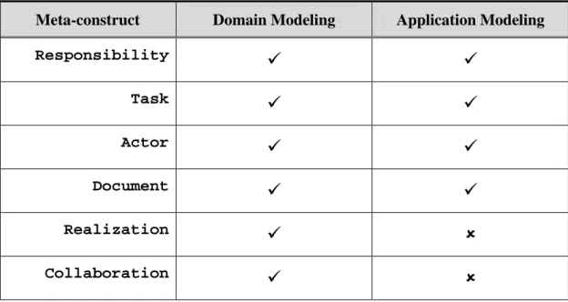
The second scenario is application modeling. In application modeling, developers create business-process responsibilities and reuse PRUs created in the domain modeling for the creation/evolution of a program which realizes the business-process responsibilities. At the same time, the experience gained in application modeling also provides feedback to evolve PRUs. This distinction is similar to product-line development [51, 52]. It is depicted in Figure 3-6. Table 3-1 summaries the occurrence of meta-construct creation in these two scenarios. To read this table, the meta-construct that has marked the symbol
9
means it is created in that scenario, otherwise, the symbol8.
Basically, those constructs related to PRU are created in the domain modeling. Otherwise, they are the application modeling.PRUs
application Feedback
Programs Domain modeling
Application modeling
Figure 3-6. Domain and application modeling
Table 3-1. Modeling scenarios of meta-constructs creation
Meta-construct Domain Modeling Application Modeling
Responsibility
9 9
Task
9 9
Actor
9 9
Document
9 9
Realization
9 8
Collaboration