Synchronization Phenomena in Coupled van der Pol Oscillators by Adding Oscillators
with Different Frequencies
Tran Minh Hai, Kosuke Oi, Yoko Uwate and Yoshifumi Nishio Dept. of Electrical and Electronic Eng.,
Tokushima University, 2-1 Minami-Josanjima, Tokushima, 770-8506 JAPAN
Email: minhhai, ooi, uwate, [email protected]
Abstract— In this work, we investigated synchronization phe- nomena observed in van der Pol oscillators coupled with star combination. By computer simulations, we confirmed some of oscillators in the system is synchronized at anti-phase. The non- linear phenomena can make synchronization such as oscillation death.
I. I NTRODUCTION
Synchronization phenomena in large populations of inter- acting elements are the subject of intense research efforts in physical, biological, chemical, and social systems.
Different kinds of synchronization are important in fields such as digital telephony, video, digital audio, frogs, human applause, etc. Now, synchronization phenomena has been studied by many researchers in various field: synchronization phenomena in van der Pol oscillators coupled by a time- varying resistor [1], synchronization phenomena observed from coupled van der Pol oscillators involving periodically forced capacitors [2], investigation on the similarity between the 2-layer CNN and the van der Pol oscillators coupled by inductors [3], consider a ring consisting of van der Pol oscilla- tors with different oscillation frequencies for investigation of large-scale circuits [4].
The van der Pol oscillator is an oscillator with nonlinear damping governed by the second-order differential equation.
It was originally proposed by the Dutch electrical engineer and physicist Balthasar van der Pol while he was working at Philips. The coupled van der Pol oscillator is one of coupled oscillators. It is very simple circuit how to study nonlinear system and important to investigate various nonlinear phenom- ena of the parametric excitation circuits for future engineering applications.
In this study, we investigate the effect to three-coupled central star circuits by adding another oscillator with differ- ent frequency. In this time, we confirmed the case of four oscillators and the case of five oscillators in the system is synchronized at anti-phase. We concentrate from the simplest case of van der Pol oscillators that oscillation frequency is varied. Fzirst, we are changing the parameter α of fourth oscillator and investigating the effect to the central star circuits
with three oscillators. The case that all of oscillators have the same oscillation. Next, we are increasing fifth oscillators with parameter and investigating the effect to the three oscillators.
We consider that many unknown phenomena remain in such systems. Therefore, it is very important to investigate such systems.
II. C IRCUIT M ODEL
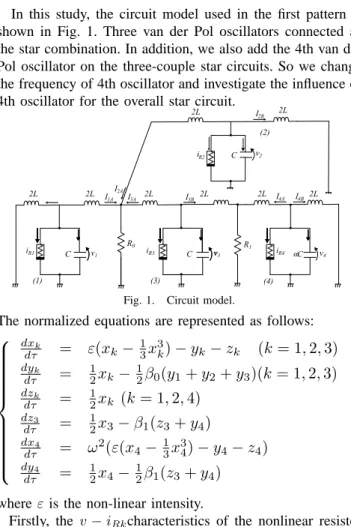
In this study, the circuit model used in the first pattern is shown in Fig. 1. Three van der Pol oscillators connected as the star combination. In addition, we also add the 4th van der Pol oscillator on the three-couple star circuits. So we change the frequency of 4th oscillator and investigate the influence of 4th oscillator for the overall star circuit.
i R1 C v 1
v 2
v 3
v v 4
i R3 i R4
i R2
v R 1
R 2L
2L 2L
2L 2L 2L 2L 2L
(4) (2)
(1) (3)
I 4A I 4B
I 3B
I 2A
I 1A
I 2B
C C
0
I 3A
C
Fig. 1. Circuit model.
The normalized equations are represented as follows:
dx k
dτ = ε(x k − 1 3 x 3 k ) − y k − z k (k = 1, 2, 3)
dy k
dτ = 1 2 x k − 1 2 β 0 (y 1 + y 2 + y 3 )(k = 1, 2, 3)
dz k
dτ = 1 2 x k (k = 1, 2, 4)
dz 3
dτ = 1 2 x 3 − β 1 (z 3 + y 4 )
dx 4
dτ = ω 2 (ε(x 4 − 1 3 x 3 4 ) − y 4 − z 4 )
dy 4
dτ = 1 2 x 4 − 1 2 β 1 (z 3 + y 4 ) where ε is the non-linear intensity.
Firstly, the v − i Rk characteristics of the nonlinear resistor are defined as follows,
- 1 -
IEEE Workshop on Nonlinear Circuit Networks
December 11-12, 2015
i Rk = − g 1 v k + g 3 v 3 k (1) By changing the variables and the parameters,
v k =
√ g 1
3g 3 x k ; i k =
√ Cg 1
3Lg 3 y k (2) α = 1
ω 2 ; t = √
L 1 Cτ. (3) and defining
β = R
√ C
L ; ε = g 1
√ L
C (4)
III. S IMULATION R ESULTS
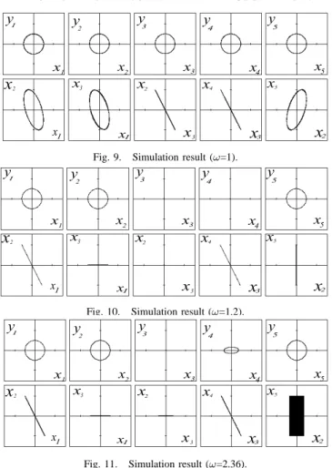
We investigate synchronization phenomena and oscillation of the oscillators by using computer simulation with β 0 =0.1 and β 1 =0.3. We investigate the change of varrying ω (ω=1 to ω=1.8). Figures 2, 3 and 4 show the simulation results.
x 4
2 x 3 4
3 4
2
y 1
x 1 x 1
x 3
x 3
x 2 x 2
x 3
y y y
x x
x 1
Fig. 2. Simulation result (ω=1).
x 4
2 x 3 4
3 4
y 1 2
x 1 x 1
x 3
x 3
x 2 x 2
x 3
y y y
x x x 1
Fig. 3. Simulation result (ω=1.2).
x 4
2 x 3 4
3 4
y 1 2
x 1 x
1
x 3
x 3
x 2 x 2
x 3
y y y
x x x 1
Fig. 4. Simulation result (ω=1.8).
In Fig. 2, in the case of ω =1, all the four oscillators oscillated. Only between 4th oscillator and 1st oscillator are synchronized at anti-phase. Consequently, we did not see the effects of omega to star circuit. And then, as the ω increases to 1.2, the oscillation of 4th oscillator and the oscillation of 3rd oscillator stop, namely oscillation death appears as shown in Fig. 3. At the same time, between the 1st oscillator and the
2nd oscillator become anti-phase synchronization. From here we can see effect of α to star circuit.
In Fig. 4, as ω increases from 1.2 to 1.8, 1st oscillator and 2nd oscillator still are anti-phase synchronization, however the fourth oscillator oscillates again and frequency of the 4th oscillator become faster than before from above 1.8 and higher.
Next, we increased ε to 0.15 and we investigate synchro- nization phenomena and oscillation of the oscillators by using computer simulation with β 0 from 0.1 and to 2.1.
In Fig. 5, in the case of ω =1, ε = 0.15, all the four oscillators oscillated and do not have any oscillators is synchronization at anti-phase. Consequently, we did not see the effects of omega to star circuit. And then, as the ω increases to 1.5, only oscillation of 3rd oscillator stop, namely oscillator death appears as shown in Fig. 5. In Fig. 7, four oscillators alway oscillate from ω = 2.1 and higher.
Fig. 5. Simulation result (ω=1).
Fig. 6. Simulation result (ω=1.5).
Fig. 7. Simulation result (ω=2.1).
IV. C IRCUIT M ODEL W ITH F IVE O SCILLATORS
Next, the circuit model used in the second pattern is shown in Fig. 8. This pattern have five oscillators in circuit. In addition, we also add the 4th and 5th van der Pol oscillator on the three-couple star circuits. So we change the frequency of 4th and 5th oscillator and investigate the influence of 5th oscillator for the overall star circuit.
- 2 -
i R1 C v 1
v 2
v 3
v v 4
i R3 i R4
i R2
v R 1
R 2L
2L 2L
2L
2L 2L 2L
2L