PAPER
Special Section on Mathematical Systems Science and its ApplicationsTemplate-Based Monte-Carlo Test-Suite Generation for Large and Complex Simulink Models ∗
Takashi TOMITA†a),Nonmember, Daisuke ISHII††,Member, Toru MURAKAMI†††, Shigeki TAKEUCHI†††,Nonmembers,andToshiaki AOKI†,Member
SUMMARY MATLAB/Simulink is the de facto standard tool for the model-based development (MBD) of control software for automotive sys- tems. A Simulink model developed in MBD for real automotive systems involves complex computation as well as tens of thousands of blocks. In this paper, we focus on decision coverage (DC), condition coverage (CC) and modified condition/decision coverage (MC/DC) criteria, and propose a Monte-Carlo test suite generation method for large and complex Simulink models. In the method, a candidate test case is generated by assigning ran- dom values to the parameters of signal templates with specific waveforms.
We try to find contributable candidates in a plausible and understandable search space, specified by a set of templates. We implemented the method as a tool, and our experimental evaluation showed that the tool was able to generate test suites for industrial implementation models with higher coverages and shorter execution times than Simulink Design Verifier. Ad- ditionally, the tool includes a fast coverage measurement engine, which demonstrated better performance than Simulink Coverage in our experi- ments.
key words: model-based development, MATLAB/Simulink, test case gener- ation, Monte-Carlo method, template-based method
1. Introduction
1.1 Background
Along with the evolution of electronic control technology, various modules have gradually electronized in the automo- tive, aircraft, and aerospace industries. How to ensure the safety and reliability ofelectronic control units(ECUs) for such modules has been a difficult challenge. IEC 61508[3], a basic functional safety standard for electronic systems in general industry, and ISO 26262[4], the specialized stan- dard for the automotive industry, were published as inter- national standards. Over the past decade, many companies have focused on developing hybrid vehicles, electric vehi- cles, driving assistance systems, and automated driving sys- tems. Hence, effective and efficient methods and techniques are strongly required for developing safe and reliable soft- ware for larger and more complex ECUs.
Manuscript received April 14, 2019.
Manuscript revised August 30, 2019.
†The authors are with Japan Advanced Institute of Science and Technology, Nomi-shi, 923-1292, Japan.
††The author is with University of Fukui, Fukui-shi, 910-8507 Japan.
†††The authors are with Gaio Technology Co., Tokyo, 140-0002 Japan.
∗This paper is a merged and revised version of parts of[1]and [2].
a) E-mail: [email protected]
DOI: 10.1587/transfun.2019MAP0010
Model-based development(MBD) is widely employed in the development of safe and reliable software for ECUs.
Usually, such software (i.e.,controller) controls a target sys- tem (i.e., plant) using feedback loops. In MBD, both the controller and plant aresimulatable, and their behaviors can be checked bynumerical simulation. A specification model for a controller is initially defined as, e.g., a system of differ- ential equations, and then refined and discretized into an im- plementation model as a fixed-point and discrete-time sys- tem with concrete data definitions and additional features, e.g., overflow measures. This model refinement can be vali- dated and verified because the models are mathematical and simulatable. Finally, such implementation models can be converted into code automatically. The quality of software is guaranteed by traceable model refinement and automatic code generation. MATLAB∗∗/Simulink∗∗∗is widely used as a de facto standard MBD tool, which provides an environ- ment for numerical operation, graphical modeling, simula- tion, and code generation.
Simulink models contain complex computations. Fur- thermore, the scale of these models becomes quite large for practical developments. We believe thattestinghas the po- tential to deal with such models and enables us to ensure the quality of the models. In fact, IEC 61508 and ISO 26262 recommend the use of some coverage criteria for testing. In model testing, atest caseis a group of input signals (and ex- pected output signals), and atest suiteis a set of test cases.
Model refinement in MBD is justified by back-to-back con- formance testing with numerical simulation. Also white- box testing based on decision coverage (DC), condition coverage (CC), and modified condition/decision coverage (MC/DC) criteria is widely employed. Typically, a release version of software must pass the tests of a full (or high, for some criteria) coverage test suite. MATLAB/Simulink has toolboxes to assist efficient testing, which conform to IEC 61508 and ISO 26262. Simulink Design Verifier∗∗∗∗
(SLDV) provides functions to detect design errors and gen- erate test cases.Simulink Coverage∗∗∗∗∗(SLC) provides cov- erage measurement functions for various criteria including DC, CC and MC/DC.
∗∗https://www.mathworks.com/products/matlab.html
∗∗∗https://www.mathworks.com/products/simulink.html
∗∗∗∗https://www.mathworks.com/products/sldesignverifier.html
∗∗∗∗∗https://www.mathworks.com/products/simulink-coverage.html Copyright c2020 The Institute of Electronics, Information and Communication Engineers
1.2 Challenges
There are several problems in the testing process of MBD for practical ECU software. First, it is difficult to obtain a full (or even high) coverage test suite for a practical model, which is large and complex. In some cases, it has tens of thousands of operations, which are called blocks in MAT- LAB/Simulink. Such blocks include (possibly non-linear) mathematical operation blocks, logical operation blocks, switch blocks, delay blocks and (conditional) subsystem blocks. SLDV provides a test case generator, but it cannot fully deal with practical models because SLDV mainly re- lies on formal analysis, wherein non-linear arithmetic leads to undecidability. Additionally, each test case is a set of time-series data. A large model has complex internal states as well as more than a hundred of inputs. A number of time- steps are sometimes required to observe a series of transi- tions of such states. So the search space for test cases be- comes huge. Formal analysis does not generally scale even in the case that is theoretically decidable. Hence, we need a feasible test generation method. TheMonte-Carlo method is often used for this purpose. This approach tries to find suitable test cases from many randomly generated candi- dates. However, we may need a useful guide for finding contributable test cases because of the massive search space we handle.
Second, the coverage measurement function cvsim provided by SLC is terribly slow when compared to the naive simulation function sim provided by the standard Simulink. In the Monte-Carlo approach, this is critical be- cause we need to generate many candidates and collate their coverage statistics. Even if we build a good test suite, we need to spend an unacceptable amount of time for checking whether the practical model passes the test suite. Cover- age measurement consists of the following parts: numeri- cal simulation with signal data logging of a given test case, and identification of time-steps that meet the coverage ob- jectives. It is necessary to accelerate this coverage measure- ment procedure to improve the efficiency of the overall test- ing process.
1.3 Contributions
The contributions of this paper are twofold. First, we pro- pose atemplate-based Monte-Carlo method[1]to automat- ically generate a test suite that achieves high DC, CC and MC/DC in MATLAB/Simulink. Second, we realize the pro- posed method as a tool[2]with an efficient coverage mea- surement engine that is critical to its performance and scal- ability.
The template-based Monte-Carlo method tries to find comprehensible test cases. A candidate test case is gener- ated by assigning random values totemplates that provide parameterized signals with specific waveforms. Therefore, the candidates are chosen from a plausible and understand- able search space specified by a set of templates.
In terms of coverage measurement, we independently implement an engine that exploits fast simulation modes and array operations, which are standard features of MAT- LAB/Simulink. This implementation is used to accelerate the signal-simulation/coverage-measurement loop, which is essential for Monte-Carlo optimization-based tools that deal with practical models.
Then, we carried out experiments to evaluate the effec- tiveness of the template-based method and the performance of the tool. We confirmed that our method can produce stimulating signals much more efficiently than naive random signal generation methods, and our tool is able to generate higher-coverage test suites in much less time than SLDV, for real implementation models developed by industry.
1.4 Organization of the Paper
The remainder of the paper is organized as follows: Sec- tion 2 introduces related work of the paper. Section 3 provides preliminary information about Simulink models and coverage testing. Section 4 proposes a template-based Monte-Carlo test-suite generation method. Section 5 de- scribes the implementation of our method. Section 6 reports evaluation experiments. Finally, we conclude in Sect. 7.
2. Related Work
Simulink Design Verifier (SLDV) is a first-party MAT- LAB/Simulink toolbox that generates test cases mainly us- ing a formal analysis. SLDV uses rational approximations of floating-point arithmetic and tries to identify suspicious test cases. Additionally, there are some third-party tools based on formal methods, e.g., BTC† Embedded Tester[5]
andAutoMOTGen[6]. Embedded Tester converts a model into a C code and generates test cases based on formal analy- sis of the C code. AutoMOTGen converts a Simulink model into a formal model, and uses model checking techniques to check whether the formal model meets formally described test objectives. However, many practical models cannot be fully dealt with by them due to limitations related to com- putability and computational complexity. Additionally, a test case produced by them may consist of input signals with any complex waveforms. In contrast, our method gen- erates test cases by template-based Monte-Carlo approach.
Although it may fail to output full-coverage test suites even for simple models, our method produces only understand- able test cases and deals with any simulatable model even if it has non-linear arithmetic.
Reactis†† is a third-party tool that consists of simula- tor, tester, and verifier. The tester tries to find a test case by combining a Monte-Carlo method and a guided simu- lation [7]. Guided simulation generates a new candidate test case from a previous one by changing its suffix after a certain time-step, which is determined based on backward
†https://www.btc-es.de/
††http://www.reactive-systems.com/
data-flow analysis.SmartTestGen[8],[9]is another tool that integrates different techniques: random testing, constraint solving, model checking, and heuristics. An input signal in- cluded in a test case generated by them may have any wave- form. In contrast, our method generates understandable can- didates based on templates that specify the characteristics of the entire waveform of the input signal.
Arandomized directed testing (REDIRECT) method [10]for state/transition coverage testing, amodel-checking based method [11] for mutation coverage testing, and an output-diversity based method[12],[13]for fault revealing were proposed. These methods aim for a test case genera- tion with criteria different from DC, CC and MC/DC.
Simulink Coverage(SLC) is a first-party toolbox for coverage testing. The details of its implementation are un- known, but the coverage measurement functioncvsimdoes not support fast simulation modes and is much slower than the naive simulation functionsim. In contrast, our tool was implemented from scratch using only standard functions in MATLAB/Simulink, and is much faster than SLC and also supports fast simulation modes.
3. Preliminaries
3.1 Simulink Models
MATLABis a general-purpose numerical computing envi- ronment with an efficient handling of arrays, matrices, im- ages, and signals. There are many first-party toolboxes, e.g., Simulink, SLDV and SLC.
Simulinkis a MATLAB toolbox for modeling and sim- ulation purpose. ASimulink modelis a block diagram that specifies a dynamical system. Ablockis a processing unit in Simulink and varies in various types, e.g.,input/output, mathematical operator,logical/relational operator,(multi- port) switch, delay, and (conditional) subsystem. Blocks are connected withlines, which transferBoolean,integer, orfloating/fixed-pointdata at each time step. Delay blocks relay data after specified delay times, and thus they brings in internal states within a model. A subsystem represents a hierarchical module in a Simulink model, and is interfaced with their parent system via input/output ports that are im- plemented with input/output blocks internally. Furthermore, a subsystem is often equipped with control ports, e.g.,en- ableandtriggerports, for selective activation/inactivation of the subsystem with external signals; also, a subsystem may mask their low-level structure, where the mask is configured with the mask variables. Usually, variables in MATLAB are stored in a base workspace. A Simulink model may refer variables in the base workspace.
The behavior of a Simulink model is characterized in terms of signals (i.e., time-series data). Inputs/outputs of blocks, subsystems and the model itself are represented as signals. In a simulation, an input signal is given to each input port of them and processed based on their descrip- tion. Processed signals are propagated to their successors via lines connected with their output ports.
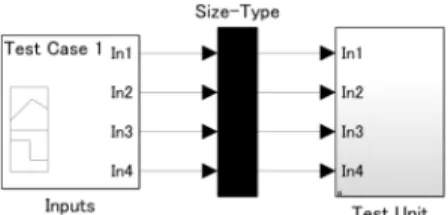
Fig. 1 Example of a harness model. A signal builder block “Inputs”
provides test cases for “Test Unit” subsystem copied from a target model via an adapter subsystem “Size-Type.”
Simulink has several simulation modes:normal,accel- erator, andrapid accelerator (or shortlyrapid). A normal mode simulator runs within the MATLAB/Simulink envi- ronment. An accelerator-mode simulator is generated as an execution engine in memory. A rapid-mode simulator is generated as a stand-alone execution file. Each mode re- quires to compile a Simulink model into an intermediate representation. For the normal and accelerator modes, we can omit recompilation by enabling thefast restartfeature.
The rapid mode requires generating an excutable file in ev- ery simulation. The accelerator and rapid modes require API communications between MATLAB/Simulink and the simulator processes.
3.2 Test Case/Suite
For the ease of testing a target model, we use a harness model (Fig. 1). A harness model consists of (i) a subsys- tem (“Test Unit”) that contains a copy of the target model, (ii) asignal builder block(“Inputs”) that provides a group of input signals for the target model, and (iii) a subsys- tem (“Size-Type”) that configures data types and sampling rates of each input signals. Because a signal builder block generates only double-typed signals, this “Size-Type”
subsystem casts each input into the signal of an appropriate type. SLDV and SLC have functions to construct a harness model of a model under testing.
Atest caseis a group of input signals, and atest suiteis a set of test cases. In Simulink, a signal block (cf. “Inputs”
in Fig. 1) can be considered as a test suite; we can add, change, or remove a test case in a signal builder block using thesignalbuilderfunction.
3.3 Test Objectives and Coverage Criteria
The objective of a model test is to attain a highmodel cov- erage, which measures how exhaustively the objects in a model are exercised, given a test case. For a test suite, the coverage of every test case is accumulated. Various cover- age criteria are proposed. In the DC, CC and MC/DC crite- ria, a measured object is a block whose activity affects the logical characteristics (i.e., data flow pattern) of the model;
thus, the test objective is broken down to the objectives for those blocks.
(1) Decision coverage (DC)
The DC criterion checks that all the possible decisional out-
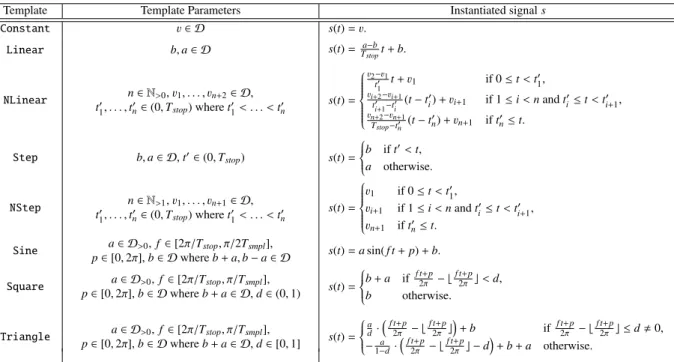
Table 1 Relations among templates, its parameters, and instantiated signals.
Template Template Parameters Instantiated signals
Constant v∈ D s(t)=v.
Linear b,a∈ D s(t)=Ta−bstopt+b.
NLinear n∈N>0,v1, . . . , vn+2∈ D,
t01, . . . ,t0n∈(0,Tstop) wheret01< . . . <t0n s(t)=
v2−v1
t10 t+v1 if 0≤t<t0
1,
vi+2−vi+1
t0i+1−ti0 (t−ti0)+vi+1 if 1≤i<nandt0i≤t<t0i+1,
vn+2−vn+1
Tstop−t0n (t−t0n)+vn+1 ift0n≤t.
Step b,a∈ D,t0∈(0,Tstop) s(t)=
b ift0<t, a otherwise.
NStep n∈N>1,v1, . . . , vn+1∈ D,
t01, . . . ,t0n∈(0,Tstop) wheret01< . . . <t0n s(t)=
v1 if 0≤t<t0
1,
vi+1 if 1≤i<nandti0≤t<t0i+1, vn+1 iftn0≤t.
Sine a∈ D>0,f ∈[2π/Tstop, π/2Tsmpl],
p∈[0,2π],b∈ Dwhereb+a,b−a∈ D s(t)=asin(f t+p)+b.
Square a∈ D>0,f ∈[2π/Tstop, π/Tsmpl],
p∈[0,2π],b∈ Dwhereb+a∈ D,d∈(0,1) s(t)=
b+a if f t+p2π − bf t+p2π c<d, b otherwise.
Triangle a∈ D>0,f ∈[2π/Tstop, π/Tsmpl],
p∈[0,2π],b∈ Dwhereb+a∈ D,d∈[0,1] s(t)=
a d·f t+p
2π − bf t+p2π c
+b if f t+p2π − bf t+p2π c ≤d,0,
−1−a
d·f t+p
2π − bf t2π+pc −d
+b+a otherwise.
comes of every block occur at some time step in a simula- tion. The coverage represents the percentage of the number of observed outcomes. Target blocks of the DC criterion are logical operators, (multiport) switches, subsystems with control ports, etc. Their decisional outcomes are Boolean outputs for logical operators, indices of passing inputs for switches, enabled/disabled for subsystems, etc.
(2) Condition coverage (CC)
The CC criterion checks that all the (satisfiable) atomic con- ditions of every block becometrueat some time step and become false at another time step. The coverage repre- sents the percentage of observed conditional outcomes. Tar- get blocks for the CC criterion are relational operators, log- ical operators, etc.
(3) Modified condition/decision coverage (MC/DC) The MC/DC criterion checks that, for every block, each atomic condition affects its decisional outcomes indepen- dently. The coverage is defined as the percentage of ob- served witness pairs of atomic conditions. Target blocks for the MC/DC criterion are multi-input logical operators, etc.
An example witness for thei-th condition of “AND” opera- tor is the pair of the outcome “all inputs aretrue(and thus the output istrue) at some time” and the outcome “only the i-th input isfalse(the output isfalse) at some time.”
4. Template-Based Monte-Carlo Method
4.1 Signal Templates
In general, a test case is characterized as a group of input signals with arbitrary waveforms. However, in MBD, the input signals to a controller are provided by other electronic
modules that are likely to be well-controlled, or by physical objects that are dominated by physical laws. In our expe- rience, it is frequently sufficient to consider input signals with several specific waveforms to achieve high DC, CC, and MC/DC. For instance, when a model contains a band- pass filter circuit, which only passes a wave-shaped signal with a specific frequency, we need to give such signal to exercise the downstream of the circuit. Some circuits are exercised by a signal keeping a specific constant value for a certain time whereas others are activated by a signal that changes its value suddenly and significantly. Therefore, we focus on a collection of such specific signals. For a test case consisting of them, the behavior of a model is relatively easy to understand for a design engineer. Thus it is helpful for re- fining the given model.
We introduce templates for input signals, and search test cases within the subset of instances of the templates.
In this paper, we provide templates Constant, Linear, NLinear, Step, NStep, Sine, Square, and Triangle, each of which represents constant, linear, piecewise- linear,single-step,multiple-step(in other words, piecewise- constant), sine-wave, square-wave, or triangle-wave sig- nals, respectively (Table 1). Note that we set the upper bound of the number n of pieces forNLinearandNStep templates in practice.
An individual input signal can be instantiated by choos- ing a template and assigning concrete values to parameters, based on (i) the rangeDof its data type, (ii) user-specified ranges, and (iii) its sampling timeTsmpl, and (iv) stop time Tstopof the target model, and then rounded based on the data type and the sampling time.
Algorithm 1Template-based Monte-Carlo test-suite gener- ation
Inputs: Simulink modelmdl, and template settingtmp Outputs: Test suitets
1: ts:=∅;
2: tsc:=null coverage;
3: repeat
4: cand:=generateTestCaseFromTemplates(mdl,tmp);
5: sd:=simulate(mdl,cand);
6: candc:=measureCoverage(mdl,sd);
7: ifa covering area ofcandcis not subset of that oftscthen 8: ts:=ts∪ {cand};
9: tsc:=accumulateCoverage(tsc,candc);
10: end if
11: untiltscachieves full coverage 12: return ts;
4.2 Algorithm
We propose a template-based algorithm for Monte-Carlo test-suite generation as shown in Algorithm 1. First, we gen- eraterandomlyan entire candidate test case (i.e., a group of input signals) based on atemplate settingspecifying a set of available templates and the ranges of their parameters for each input (Line 4). Each input signal is instantiated from one of templates in Table 1. All templates in Table 1 are available and the ranges of their parameters are assumed as wide as possible by default, however, a user can customize the setting. Second, we simulate the target model for the candidate with signal logging (Line 5). Third, we measure its coverage from the simulation log (Line 6). Fourth, if the candidate is contributable to the coverage, we add it to the test suite (Lines 7–10). The steps are repeated until the test suite achieves full coverage.
If, for each DC, CC, or MC/DC objective of the tar- get model, there exists a test case meeting the objective in the setT of possible test cases instantiated from the avail- able templates, and if each candidate is chosen randomly and uniformly fromT, Algorithm 1 returns a full coverage test suite eventually.
However, there is generally no ground for the existence of a suitable test case inT for each objective. Additionally, if a specific value is required to meet an DC, CC, or MC/DC objective, the probability to choose it by random and uni- form sampling is very low. Therefore, we practically set the maximum number of repetitions, i.e., that of candidates.
When the size of the test suite reaches the maximum num- ber, the procedure will halt even if the test suite does not achieve full coverage.
4.3 Discussions
The template-based approach has several benefits. First, it is efficient in generating a test case. A general signal is naive time-series data, so it has as many parameters as the time- steps of a simulation. A number of parameters are required to be examined to observe a complex behavior in a simula- tion with a certain length. On the other hand, a template- based signal is characterized by only a few parameters,
which is independent of the length of a simulation. When an appropriate template is selected, test case generation be- comes efficient by assigning concrete values for the reduced number of parameters. Second, the intention of a test case becomes understandable. The definition of a template de- termines the waveform of instantiated signals. Ramp-like, pulse-like and sawtooth signals can be instantiated from the NLinear,NStep(orSquare) andTriangletemplates, re- spectively. According to the definitions of templates, we can easily classify the signals and understand their charac- teristics. Additionally, we can extend our method by adding another template as needed.
As a trade-offof the benefits, the template-based ap- proach cannot deal with complex shaped signals, and hence it may be impossible to cover some objective using any template-based test case. Additionally, it is difficult, or rather impossible, to know whether a given objective can be covered with signals instantiated from available templates, in advance. Note that there is another issue in handling a complex-shaped signal with a template because it might be an unrealistic signal.
A general advantage of Monte-Carlo approaches is that we can deal with any model, e.g., that involving non-linear computation. The Monte-Carlo test suite generation does not require to analyze the behavioral characteristics of the target model. We need only an analysis for coverage mea- surement. A static/dynamic analysis of the target model en- ables us to predict a hopeful search space (i.e., templates and the ranges of their parameters in the template-based method), but it is optional.
As a general disadvantage of naive Monte-Carlo ap- proaches, we cannot deny the possibility that we fail to solve even a small problem. The difficulty of static formal anal- ysis, e.g., constraint solving, strongly depends on the com- plexity of operations, i.e., the number/types of signals and blocks. On the other hand, that of our naive Monte-Carlo approach depends on only the size of the search space for test cases, i.e., the product of ranges of parameters of (tem- plates assigned for) top-level input signals. So, if a desired test case can be instantiated only by a combination of values in a very narrow region against the search space, we may not find it within an acceptable length of time. This is be- cause it is almost impossible to randomly choose a specific value from a nearly continuous search space without a user- specific limitation. This kind of difficulty is typically related with a DC/CC objective checking that a floating/fixed-point input value is equivalent to another input or constant. How- ever, such cases are very rare in practical models.
5. Implementation
We implemented the template-based Monte-Carlo method as a tool, which contains an efficient coverage measurement engine as a replacement for the first-party implementation cvsimof SLC.
A design overview of our tool is provided in Fig. 2. The tool consists of a structure analyzer, test case generator,
Fig. 2 Overview of the tool.
simulator, andmetric measurer, and realizes Algorithm 1 by cooperation among them. The structure analyzer performs preprocesses for test generation. The test case generator generates new candidate test cases (Line 4 in Algorithm 1).
The simulator configures the logging settings of the harness model and simulates it (Line 5 in Algorithm 1). The metric measurer receives simulation logs of test cases, and evalu- ates/compares/accumulates the coverages of the test cases (Lines 6, 7, 9 and 10 in Algorithm 1).
These modules are implemented as MATLAB scripts, and call standard MATLAB/Simulink functions for analysis, modification, and simulation of Simulink models.
5.1 Structure Analyzer
Our tool performs a static analysis of the structure of the model as a preprocess for test suite generation, simulation, and metric measurement. The primary functional features of the structure analyzer are: (1) listing of all blocks and connections between them as well as their parameter val- ues, (2) detection of the signal builder block and the adapter subsystem of a harness, and (3) identification of all target blocks for DC, CC and MC/DC and the lines connected to their inputs from the target model.
The analyzer scans all blocks, including lower-level blocks in masked subsystems, recognizes their predecessors, successors and higher/lower-level blocks, and determines their concrete parameter values (e.g., a value of a constant block, a threshold of a switch block) based on mask vari- ables of their higher-level subsystems and variables in the base workspace of the MATLAB environment.
Signals flowing on the lines between blocks may be multiplexed using multiplexer or bus-related blocks. Hence, the analyzer also temporally compiles the model and col- lects the multiplicity and data-type information for each of the lines.
5.2 Test Case Generator
The test case generator prepares a signal for each top-level input of “Test Unit,” based on a template. The primary functional features of the test case generator are: (1) pars- ing of a text file specifying a template setting, (2) random
value generation, and (3) test case instantiation based on the templates and the random values.
A template setting specifies available templates and ranges (maximum and minimum values) of the parameters for each top-level input of “Test Unit” Note that multi- ple ranges may be available for each parameter. Each range may be adjusted based on the data type recognized by the analyzer. Currently, our tool supports templates given in Ta- ble 1. A user can customize a template setting by giving a text file. An example of lines of such template setting file is given as follows.
The example specifies three templates for the top-level input named “In 1.” The first line specifies aSteptemplate with parameter constraintsb∈[0,10],a∈[10,20] andt0∈[0,5].
The first line specifies anotherSteptemplate with parame- ter constraintsb∈[10,20],a∈[0,10] andt0∈[5,10]. The third line specifies a NStep template with parameter con- straints n ∈ [2,5] andv1, . . . , vn+1 ∈ [0,5]∪[15,20] and t01, . . . ,t0n∈[0,Tstop].
The generator chooses one from the available templates (resp., ranges) for each input (resp., for each parameter of a chosen template) randomly and uniformly, and then instan- tiates a candidate test case by assigning uniformly-random values to the parameters from the chosen ranges. Note that, we can specifically assign a certain value to a parameter of interest by using a singleton range. Therefore, we can re- duce the disadvantage of Monte-Carlo approach, i.e., we can obtain a signal instantiated by a combination of specific val- ues with a certain probability if we know each of them in advance.
Then the candidate is temporarily added to the test suite (Line 8 in Algorithm 1) by editing “Inputs,” i.e., calling the signalbuilderfunction. If the candidate is not con- tributable, the generator replaces it by the next candidate.
5.3 Simulator
The simulator is a wrapper for a standard Simulink simu- lation functionsim. The primary functional features of the simulator are: (1) making a mapping table between output
ports and signal identifiers, (2) configuring the simulation settings, e.g., on signal logging and simulation mode, and (3) simulating the harness model for a test case in an arbi- trary simulation mode.
Based on block information provided by the analyzer, the simulator gives unique names to each output port of the predecessors of target blocks of DC, CC, and MC/DC crite- ria. Hence, we can access the logged signal flowing out of a given output port via the corresponding name.
The simulator activates the newest test case by call- ing thesignalbuilderfunction and then invokes thesim function. Here, simulation can be performed with any sim- ulation mode: normal, accelerator, or rapid.
5.4 Metric Measurer
The metric measurer collects signal data of interest from the simulation log and evaluates the metrics for that test case. The primary functional features of the metric mea- surer are: (1) coverage measurement for a test case, (2) com- paring/accumulating coverages of test cases/suites, and (3) reporting the accumulated coverage result for a test suite.
For each target block of the DC, CC, and MC/DC cri- teria, the measurer reads the signal logs fed into the block, which are identified by the names given by the analyzer.
5.4.1 Coverage Measurement
According to the types of conditions and/or decisions and parameters of a block, the measurer evaluates the outcomes of the conditions and/or decisions at each step. The cov- erage for the block is derived from the time series of the outcomes. Then, the measurer sums up the coverages for each target block to calculate the coverage for the test case.
The coverage for a test suite is obtained by summing the individual coverages for each test case.
5.4.2 Comparison with SLC
In this section, we explain our coverage measurement en- gine, and contrast it with the coverage measurement func- tioncvsimprovided by SLC. As SLC is a proprietary soft- ware, our observation here is based on our experiments.
(1) Features of SLC coverage measurement
Normal mode is the only simulation mode supported by cvsim. Accelerator and rapid modes are not supported. In- stead, we can pause simulation and immediately obtain in- termediate results. Based on this observational evidence, we inferred thatcvsimrepeats the following steps: (i) advanc- ing the simulation by a step, (ii) checking whether each de- cision/condition holds, and incrementing a counter for each objective if it is satisfied at that time. This approach pro- cesses a time series data in afor-loop and is very inefficient.
(2) Features of our coverage measurement
In contrast, our tool employs the following approach: First,
based on structure analysis, we enable logging for all output ports, which provide signals feeding in blocks that should be measured. Second, a target harness model is simulated until completion without pause. Finally, we check whether every decision/condition holds for each step and count the number of steps that satisfy decisions/conditions by apply- ing array/matrix operations to the simulation log. In this ap- proach, we can use any simulation mode because we assume that simulations are pauseless. Therefore, we can accelerate coverage measurement by using fast simulation modes and efficient array/matrix operations of MATLAB/Simulink.
6. Evaluation
This section shows experimental evaluations. All of the experiments were done with macOS 10.13.4 and MAT- LAB/Simulink (including SLDV and SLC) R2017b on a PC with a 2.8 GHz Intel Core i7 CPU and 16 GB of RAM.
6.1 Basic Evaluation
First, we report the results of basic experiments with small models to evaluate the effectiveness of our template-based method proposed in Sect. 4. In the experiments, we used three modelsm1,m2andm3given in Fig. 3. SLDV can gen- erate a full coverage test suite form1andm2, but cannot for m3even with more than an hour.
Fig. 3 Small models for basic experiments. Form1, the value range of its input signal is [0,1000], its detect threshold is 500 for a time step. For m2, the value range of its input signal is [0,1000], its detect threshold is 0.1 for 10 time steps. Form3, the value range of its input signal is [−1,1], its pass frequency is around 0.63-0.68 rad/s, its detect threshold is 0.9. For all of them, sample time is 1s and stop time is 1,000s.
(1) Descriptions
We compared the following randomized methods.
1. Uniform Random: For each time step, a value of an input signal is uniformly and randomly chosen from the value range.
2. Wiener-process: The initial value of an input signal is uniformly and randomly chosen from the value range.
A change for each time step follows a (truncated) nor- mal distributionN(0, σ2) where the standard deviation σis uniformly and randomly chosen, once for each test case, from a hundredth of the width of the value range.
3. Our method (Algorithm 1): A test case is generated by our method with the following setting, called “ALL”:
all templates in Fig. 1 are enabled, and any additional constraints for template parameters are not given. For onlym3, we also use the following setting, called “SS”:
“Sine” template with constraints “amplitude and bias is fixed to 1 and 0, respectively” and “Square” tem- plate with constraints “amplitude and bias is fixed to 2 and−1, respectively” are enabled, and all other tem- plates are disabled.
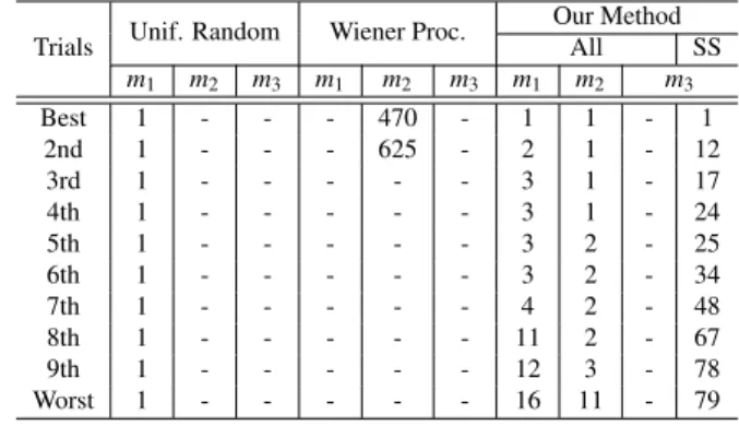
We observed 10 trials for each of them and models. For each trial, we repeatedly generated candidate test cases (up to 1,000) and measured its coverage, and scored the number of candidates required to achieve full coverage.
(2) Results
The results are summarized in Table 2. Hyphens mean that the numbers of candidates exceed 1,000. Each trial com- pletes up to few minutes. Random signals are extremely un- stable, thus only sudden changes were normally observed.
Wiener-process signals with smaller variances are more sta- ble, therefore steady states were observed when its variances were enough small. The results indicate that these naive types of random signals is suitable only in limited cases.
Our template-based method assumes various types of sig- nal templates, so got to normally produce stimulating sig- nals. Form3, our method required a suitable template setting to efficiently generate contributable test cases, because few templates are suitable for band-pass filter and the conditions for parameters to pass the filter are strict. Although, for each input signal, the range of its values and considered types of its waveforms are usually limited and known by modeling engineers. So it is expected to improve the efficiency of our method by giving a suitable template setting as suggestions based on such their knowledge.
6.2 Practical Evaluation
Second, we report two experimental results to practically evaluate the quality of the generated test suites (Sect. 6.2.1) and the coverage measurement performance (Sect. 6.2.2) of our tool introduced in Sect. 5.
In the experiments, we focused on implementation
Table 2 Sorted numbers (from the best case to the worst case) of candi- dates to fully cover objectives in small modelsm1,m2andm3.
Trials Unif. Random Wiener Proc. Our Method
All SS
m1 m2 m3 m1 m2 m3 m1 m2 m3
Best 1 - - - 470 - 1 1 - 1
2nd 1 - - - 625 - 2 1 - 12
3rd 1 - - - - - 3 1 - 17
4th 1 - - - - - 3 1 - 24
5th 1 - - - - - 3 2 - 25
6th 1 - - - - - 3 2 - 34
7th 1 - - - - - 4 2 - 48
8th 1 - - - - - 11 2 - 67
9th 1 - - - - - 12 3 - 78
Worst 1 - - - - - 16 11 - 79
Table 3 Summary of experimental modelsM1andM2.
Attributes M1 M2
#Inputs 2 51
#uint8-typed signals 0 7
#int16-typed signals 1 3
#uint16-typed signals 0 1
#single-typed signals 0 40
#double-typed signals 1 0
#Blocks 476 2374
#RelationalOperator blocks 16 120
#Logic blocks 7 7
#Switch blocks 1 152
#MultiPortSwitch blocks 33 42
#Abs blocks 0 1
#MinMax blocks 0 1
#If blocks 0 11
#Subsystems 29 145
#Enable subsystems 2 4
#Trigger subsystems 5 0
#IfAction subsystems 0 24
#Objectives 200 710
#DC objectives 123 428
#CC objectives 64 268
#MC/DC objectives 13 14
StopTime 3.0 7.0
SampleTime (base) 1/20000 1/1000
models of realistic applications. To the best of our knowl- edge, there are no open benchmarks of such models. We have evaluated our tool with several industrial models and obtained good results, however, all of the models are confi- dential and most of the results cannot be open. In this paper, we report the summarized results for (closed-source) two Simulink models M1andM2 developed as real products in the industry; statistical data are summarized in Table 3. Note that, two and (at least) 56 objectives in M1andM2, respec- tively, are unsatisfiable. They are detected by SLDV and confirmed manually.
6.2.1 Quality of Generated Test Suite
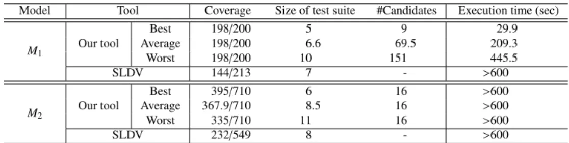
In the first experiment, we compared the coverages of test suites generated by our tool with those generated by SLDV.
Table 4 Comparison between qualities of generated test suites.
Model Tool Coverage Size of test suite #Candidates Execution time (sec)
M1 Our tool
Best 198/200 5 9 29.9
Average 198/200 6.6 69.5 209.3
Worst 198/200 10 151 445.5
SLDV 144/213 7 - >600
M2 Our tool
Best 395/710 6 16 >600
Average 367.9/710 8.5 16 >600
Worst 335/710 11 16 >600
SLDV 232/549 8 - >600
(1) Description
We generated test suites forM1andM2in two ways, using either our tool or SLDV. Then, we compared the coverages, sizes of test suites (i.e., numbers of contributable test cases), number of candidates (for our tool), and execution times.
The timeout was set to 600 seconds.
For our tool with the Monte-Carlo approach, we per- formed 20 trials for each model. Increasing the number of trials was effective when revealing the characteristics of the target models, but had only a minor benefit to evalu- ate the quality of a Monte-Carlo based tool. The simula- tions in all trials were performed in accelerator mode with the fast restart option. We used the following template set- tings: forM1, we enabled the templates suggested by indus- try engineers for both top-level inputs:Stepfor theint16- typed input, andConstant,LinearandSinefor the other double-typed input. The engineers also provided the ranges of the parameter values. For M2, we enabled Step and Linear templates for every top-level input. We used the default ranges of the parameter values (i.e., those of the cor- responding data types for the inputs).
In contrast, we only observed one SLDV trial for each model due to its non-randomness.
(2) Results
Our results are summarized in Table 4. Our tool employs a randomized method, so we list the best, average, and worst values among the 20 trials. The execution times for our tool include the time taken for the structure analysis. The differ- ences between the total numbers of DC, CC, and MC/DC objectives on M1 are due to the differences between the MC/DC objective counting policies. Our tool (resp., SLDV) count 1 (resp., 2) for each witness pair of MC/DC criterion.
Additionally, SLDV ignored the unsupported objectives on M2, e.g., those related to blocks in the downstream of non- linear arithmetic. This is clear because the total number of objectives was less than double the number of relational op- erator blocks and (multiport) switches.
The experimental results demonstrate that our tool can achieve higher coverage than SLDV, with shorter execution times, against practical implementation models. In the case of the medium-sized model M1, the coverage achieved by SLDV was only 70%, but all trials of our tool achieved prac- tically full coverage (because 2 objectives are unsatisfiable) with short execution times, thanks partly to suggestive tem-
Table 5 Comparison on performance on coverage measuring.
Model Tool Sim. mode Exec. time (sec)
M1 Our tool
Normal 1.8
Accelerator 2.9
Rapid 10.2
SLC Normal 50.6
M2 Our tool
Normal 54.6
Accelerator 38.5
Rapid 30.0
SLC Normal 258.4
plate settings from the engineers. Neither tools achieved full coverage in the case of large modelM2, but all trials of our tool covered more objectives than SLDV even without sug- gestive template settings.
6.2.2 Performance on Coverage Measurement
In the second experiment, we compared the performances on coverage measurement of our tool to that of SLC.
(1) Description
For M1 andM2, we observed execution times of coverage measurement of our tool and SLC under each available sim- ulation mode. For each model, we used a test suite consist- ing of 20 test cases generated by our tool.
We enable the fast restart option in the normal and ac- celerator modes, so the execution times did not include the recompilation for simulation. In the case of rapid mode, the fast restart option must be disabled, and the recompilation is unavoidable for each simulation. Hence, in this case, the execution times included every recompilation time for sim- ulation.
(2) Results
We assessed the execution times of coverage measurement of our tool and SLC, and then calculated the average time per test case. Note that the coverage measurement has no randomness, and therefore, for each tool and each model, the execution times for test cases were almost the same. Our results are summarized in Table 5.
The experimental results confirm that our tool performs better than SLC. Our tool evaluated the coverage about 5 times faster than SLC in each simulation mode. In particu- lar, our tool ran more than 25 times faster than SLC in some cases. In the case of M1, the faster simulation modes were slower than the normal mode. We conjecture that the re-
compilation and API communication overheads of the faster simulation modes have a more significant effect when test- ing smaller models. Actually, in our manual measurement, most of execution times in the rapid mode were taken for recompilation. Conversely, we conclude that using faster simulation modes is very effectively when measuring test coverage for large models.
7. Conclusions
In this paper, we proposed a scalable test suite generation method, based on signal templates, for practical Simulink models, and implemented it as a tool. The tool succeeded in dealing with real implementation models used in indus- try and generated a higher-coverage test suite than the first- party toolbox SLDV. Moreover, the tool evaluates test cov- erage much faster than the first-party toolbox SLC. This en- ables it to generate and check more candidates per hour.
Thus, we can obtain effective test cases within a reasonable length of time.
In the future, we will improve the sophistication of the tool based on the results of trials in real development teams. Furthermore, we will combine the current method with light-weight formal analysis that can narrow the range of values of template parameters. In contrast to using con- servative approximations in purely formal approaches, we may accept loose approximations for this light-weight anal- ysis. It is enough useful to extract hopeful regions from the search space. Heuristic techniques will improve the effi- ciency of test suite generation.
References
[1] T. Tomita, D. Ishii, T. Murakami, S. Takeuchi, and T. Aoki,
“Template-based Monte-Carlo test generation for Simulink mod- els,” Cyber Physical Systems. Design, Modeling, and Evaluation, R. Chamberlain, W. Taha, and M. T¨orngren, eds., LNCS 11267, pp.63–78, Springer International Publishing, 2019.
[2] T. Tomita, D. Ishii, T. Murakami, S. Takeuchi, and T. Aoki, “A scal- able Monte-Carlo test-case generation tool for large and complex Simulink models,” Proc. 11th Workshop on Modelling in Software Engineering, MiSE’19, pp.39–46, IEEE Press, 2019.
[3] International Electrotechnical Commission, “IEC 61508 func- tional safety of electrical/electronic/programmable electronic safety- related systems.”
[4] International Organization for Standardization, “ISO 26262 road ve- hicles – functional safety.”
[5] P. Schrammel, D. Kroening, M. Brain, R. Martins, T. Teige, and T. Bienm¨uller, “Incremental bounded model checking for embedded software,” Formal Aspects of Computing, vol.29, no.5, pp.911–931, Sept. 2017.
[6] S. Mohalik, A.A. Gadkari, A. Yeolekar, K. Shashidhar, and S. Ramesh, “Automatic test case generation from Simulink/Stateflow models using model checking,” Softw. Test. Verif. Reliab., vol.24, no.2, pp.155–180, 2014.
[7] S. Sims and D.C. DuVarney, “Experience report: The Reactis val- idation tool,” Proc. 12th ACM SIGPLAN International Conference on Functional Programming, ICFP’07, pp.137–140, New York, NY, USA, ACM, 2007.
[8] P. Peranandam, S. Raviram, M. Satpathy, A. Yeolekar, A. Gadkari, and S. Ramesh, “An integrated test generation tool for enhanced cov- erage of Simulink/Stateflow models,” Proc. Conference on Design,
Automation and Test in Europe, DATE’12, pp.308–311, San Jose, CA, USA, EDA Consortium, 2012.
[9] S. Raviram, P. Peranandam, M. Satpathy, and S. Ramesh,
“SmartTestGen+: A test suite booster for enhanced structural cov- erage,” Theoretical Aspects of Computing – ICTAC 2012, A. Roy- choudhury and M. D’Souza, eds., pp.164–167, Berlin, Heidelberg, Springer Berlin Heidelberg, 2012.
[10] M. Satpathy, A. Yeolekar, and S. Ramesh, “Randomized di- rected testing (REDIRECT) for Simulink/Stateflow models,” Proc.
8th ACM International Conference on Embedded Software, EM- SOFT’08, pp.217–226, New York, NY, USA, ACM, 2008.
[11] A. Brillout, N. He, M. Mazzucchi, D. Kroening, M. Purandare, P. R¨ummer, and G. Weissenbacher, “Mutation-based test case gen- eration for Simulink models,” Formal Methods for Components and Objects, F.S. de Boer, M.M. Bonsangue, S. Hallerstede, and M. Leuschel, eds., pp.208–227, Berlin, Heidelberg, Springer Berlin Heidelberg, 2010.
[12] R. Matinnejad, S. Nejati, L.C. Briand, and T. Bruckmann, “Au- tomated test suite generation for time-continuous Simulink mod- els,” Proc. 38th International Conference on Software Engineering, ICSE’16, pp.595–606, New York, NY, USA, ACM, 2016.
[13] R. Matinnejad, S. Nejati, L.C. Briand, and T. Bruckmann, “Sim- CoTest: A test suite generation tool for Simulink/Stateflow con- trollers,” Proc. 38th International Conference on Software Engineer- ing Companion, ICSE’16, pp.585–588, New York, NY, USA, ACM, 2016.
Takashi Tomita received the B.S., M.S., and Ph.D. degrees in engineering from Tokyo Institute of Technology in 2007, 2009, and 2013, respectively. During 2013–2015, he was a re- searcher in the institute. Since 2015, he has been an assistant professor at Japan Advanced Insti- tute of Science and Technology. He is engaged in the researches on formal methods, quantita- tive verification, probabilistic/statistical model checking, specification verification, automated program synthesis, and systems biology.
Daisuke Ishii received the B.Eng., M.Eng., and Ph.D. degrees in computer science from Waseda University in 2001, 2003, and 2010, respectively. He was a research fellow at IN- RIA/LINA in France (2010–2011), a research fellow of the JSPS at National Institute of Infor- matics (2011–2013), and an assistant professor at Tokyo Institute of Technology (2013–2015).
He is currently an associate professor at Uni- versity of Fukui. His research interests include interval analysis and formal methods for hybrid systems.
Toru Murakami was a manager of En- gineering Department, Cybernet Systems Cor- poration (an agent company of MathWorks in Japan), until 2011. Currently, He is a model- based development expert in Technology De- velopment Division, Gaio Technology Corpo- ration. He is engaged as a chief consultant on the model-based development in OEM/supplier companies.
Shigeki Takeuchi was a system architect and manager of in-vehicle infotainment system with the model-based development in Sony Cor- poration until 2013. Currently, He is a deputy general manager in Technology Development Division, Gaio Technology Corporation. He has examined model-based systems engineering that integrates the model-based design and the model-based test for OEM/supplier companies.
Toshiaki Aoki is a professor in Division of Transdisciplinary Sciences and School of Infor- mation Science, JAIST. He received B.S. degree from Science University of Tokyo (1994), M.S.
and Ph.D. from Japan Advanced Institute of Sci- ence and Technology (1996, 1999). His research interests include formal methods, formal verifi- cation, theorem proving, model checking, auto- motive systems and embedded systems.

![Fig. 3 Small models for basic experiments. For m 1 , the value range of its input signal is [0, 1000], its detect threshold is 500 for a time step](https://thumb-ap.123doks.com/thumbv2/123deta/5633373.1501397/7.892.491.789.624.1021/small-models-basic-experiments-value-signal-detect-threshold.webp)