THE THESIS OF DOCTOR OF PHILOSOPHY
Study on an Amphibious
Father-son Robotic System
Maoxun Li
Graduate School of Engineering Kagawa University
Abstract I
Ph.D. thesis of Dr. Maoxun Li
Abstract
With the increasing needs for underwater intervention tasks, underwater vehicles have been extensively applied in intervention missions instead of human. To implement the underwater intervention, a father-son robotic system was proposed, which is composed of an amphibious father robot and several microrobots used as the manipulators of the system. We have described a spherical robot configuration for amphibious applications. The amphibious robot can move with a relatively high velocity and for a relatively long period of time on land and underwater. Furthermore, by carrying the microrobot, the robot can be employed to do the sample collections and monitoring in an underwater space.
An amphibious spherical robot that consists of a sealed upper hemispheroid, two quarter spherical shells, and a plastic circular plate was proposed. It has a plastic shelf for carrying the microrobots, and four actuating units for movement. Each unit is composed of a water-jet propeller and two servomotors, each of which can rotate 90º in the horizontal and vertical directions. The robot is capable of motion on land, as well as underwater. A braking mechanism is designed to transform the state of each passive wheel between free rolling and braking states by compressing and releasing the spring, which is controlled by the vertical servo motor on each leg. Besides, in order to
II Study on an Amphibious Father-son Robotic System
improve the walking stability of the wheeled robot in longitudinal direction, a closed-loop control method is presented to control the stability of the direction of movement while walking.
The on-land experiments on smooth flat surface and on a slope were carried on to evaluate the on-land performance of the amphibious robot. At low frequencies, the sliding velocity and walking velocity on the flat terrain were roughly equal. At a control frequency of 5.56 Hz, we got a maximum roller-skating velocity of 37.8 cm/s. And the robot was able to move down a slope with an incline of 10 ° with roller-skating gait. Roller-skating gait showed a better performance than walking gait in terms of mobile velocity and energy efficiency, especially moving down a slope.
Since there is a different step loss for four legs during walking, the direction of movement of the robot is unstable. For the improvement of the walking stability of the wheeled robot in longitudinal direction, we proposed a closed-loop control method by carrying a gyroscope sensor to measure the yaw angle of the robot in real time. And plenty of walking experiments were conducted to evaluate a good performance of directional control.
Additionally, underwater thrust and velocity experiments in the semi-submerged state were conducted to evaluate the underwater performance. Under a duty of 100%, we got a maximum thrust of 180 mN in horizontal direction, and a maximum upward thrust of 333.2 mN
Abstract III
Ph.D. thesis of Dr. Maoxun Li
and a downward thrust of 362.6 mN in vertical direction. And a maximum surge velocity of 16.1 cm/s and rotational velocity of 64.3 º/s were obtained, and a maximum rising velocity of 8.4 cm/s and a sinking velocity of 8.4 cm/s were achieved. Furthermore, the microrobot deployment experiment was carried out to prove the feasibility of the fixture and deployment mechanism.
As the crucial equipment of underwater vehicles, underwater manipulators typically play an important role in the underwater tasks. An ICPF actuator-based crayfish-like son robot has been developed to be adopted as the manipulator of the father-son robot system. The son robot is actuated by ten ICPF actuators, which can perform walking, rotating and grasping motions underwater. A proximity sensor and two photodiodes are mounted in front of the microrobot to implement the functions of autonomous grasp and blue LED tracking. A blue LED-based underwater optical communication system is designed to enable the communication between father robot and son robot for the microrobot recovery.
The walking, rotating and grasping experiments are conducted to verify the performance of the basic motions of the robot. From the experimental results, a maximum walking speed of 18.6 mm/s and a maximum rotational speed of 0.51 rad/s at a control frequency of 3 Hz are achieved. We also carry out the underwater experiments to evaluate the performance of the optical communication system, in which the
IV Study on an Amphibious Father-son Robotic System
blue LED and the photodiode are used as the transmitter and the receiver respectively. By measuring the detectable maximum distance of the photodiode at different input angles, we achieve the detectable range of the communication system. From the results of the blue LED-based tracking experiments, the microrobot can be recovered by the father robot.
And a biomimetic cableless microrobot has been developed as the manipulator of the father-son robot system. The microrobot actuated by nine ICPF actuators can implement the walking, rotating and grasping motions. A blue LED-based underwater optical communication method was proposed to realize the communication between the father robot and the cableless son robot. The father robot is able to carry the cableless son robot and send the optical signals to control the motion of it according to the proposed communication protocol.
The walking and rotating experiments were conducted to evaluate the performance of the microrobot. From the experimental results, a maximum walking speed of 9.85 mm/s and rotational speed of 13.13 º/s were achieved at a control frequency of 1.25 Hz. Finally, the communication experiments were carried out to verify that the proposed communication protocol can be used for the communication between the father and son robot.
Contents V Ph.D. thesis of Dr. J
Contents
Abstract ... I Contents ... V List of Table... IX List of Figures ... X Acknowledgements ...XVII Declaration ... XVIII Chapter 1 Introduction ... 19 1.1 Thesis scope ... 19 1.2 Literature review ... 22 1.3 Thesis objectives ... 32 1.4 Thesis structure ... 33Chapter 2 Overview of the father-son robotic system ... 35
2.1 The amphibious spherical father robot ... 37
2.2 The proposed son robots ... 38
2.3 Summary ... 39
Chapter 3 Proposed amphibious father robot with three actuation modes ... 41
3.1 General design ... 41
3.2 Actuation and control system ... 44
VI Study on an Amphibious Father-son Robotic System
3.2.2 Roller-skating actuation system ... 48
3.2.3 Braking/Transformation Mechanism ... 54
3.2.4 Water-jet actuation system ... 58
3.2.5 Sensing mechanism ... 61
3.3 Electrical system and power supply ... 62
3.4 Summary ... 64
Chapter 4 Performance evaluation and improvements of the father robot ... 65
4.1 Prototype father robot ... 65
4.2 Sliding/walking experiments on a smooth flat surface ... 66
4.3 Sliding/Walking Experiments on a Slope ... 69
4.4 Closed-loop control of the direction of movement ... 72
4.4.1 Design of the closed-loop control system ... 72
4.4.2 Performance evaluation of the gyroscope sensor ... 75
4.4.3 Closed-loop control experiments ... 77
4.5 Underwater experiments and analysis ... 80
4.5.1 Underwater thrust experiments ... 80
4.5.2 Underwater velocity experiments ... 86
4.6 Summary ... 90
Chapter 5 Proposed insect-like cable son robot as the manipulator ... 92
5.1 ICPF actuators ... 92
5.2 General design of son robot ... 93
Contents VII
Ph.D. thesis of Dr. Maoxun Li
5.3.1 Walking and rotating mechanisms ... 94
5.3.2 Grasping mechanism ... 96
5.4 Performance evaluations ... 97
5.4.1 ICPF actuators ... 97
5.4.2 Proximity sensor ... 101
5.5 Prototype microrobot and experiments ... 102
5.5.1 Prototype microrobot ... 102
5.5.2 Walking/rotating experiments in a water tank ... 103
5.5.3 Grasping experiments ... 105
5.6 Summary ... 106
Chapter 6 Proposed biomimetic cableless son robot as the manipulator ... 107
6.1 Design of the underwater mcrorobot ... 107
6.2 Mechanisms of the walking and rotating motions ... 108
6.3 Proposed underwater communication system ... 109
6.4 Communication protocol ... 116
6.5 Prototype microrobot and experiments ... 120
6.5.1 Prototype microrobot and performance evaluation of the ICPF actuators ... 120
6.5.2 Experiments of walking and rotating motions in a water tank ... 122
6.5.3 Communication experiments ... 123
VIII Study on an Amphibious Father-son Robotic System
Chapter 7 Deployment and recovery of the manipulator by the father
robot ... 127
7.1 Fixture/release mechanism of the microrobots ... 127
7.2 Recovery mechanism of the microrobots ... 129
7.3 Summary ... 130
Chapter 8 Conclusions and future work ... 132
8.1 Conclusions ... 132
8.2 Future work ... 136
References ... 137
Publication List ... 148
Contents IX
Ph.D. thesis of Dr. Maoxun Li
List of Table
TABLE I. Binary encoding rules for the motion control of the
X Study on an Amphibious Father-son Robotic System
List of Figures
Figure 1- 1 ACM-R5 developed by Tokyo Institute of Technology [1]
... 24
Figure 1- 2 Whegs Case Western Reserve University, USA [2] ... 25
Figure 1- 3 AmphiRobot-II developed by Chinese Academy of Sciences [3] ... 26
Figure 1- 4 AmphiHex-I developed by University of Science and Technology of China [7] ... 26
Figure 1- 5 Roller-Walker [8]-[11] ... 29
Figure 1- 6 AZIMUT [14] ... 29
Figure 1- 7 SAUVIM developed by University of Hawaii [15] ... 30
Figure 1- 8 RAUVI developed by University of Bologna [18]... 30
Figure 1- 9 The main vehical equipped with highly maneuverable agent ROV [19] ... 31
Figure 1- 10 The structure of the thesis ... 34
Figure 2- 1 The conceptual design of the father-son robotic system (cable son robot) ... 36
Figure 2- 2 The conceptual design of the father-son robotic system (cableless son robot) ... 36 Figure 2- 3 Father-son robot configuration: (a) prototype of the
List of Figures XI
Ph.D. thesis of Dr. Maoxun Li
father-son robot system ... 37
Figure 3- 1 Structure of the amphibious spherical robot ... 43 Figure 3- 2 Opening mechanism of the amphibious spherical robot .... 43 Figure 3- 3 Structure of the robot in three actuating modes: (a) overall
structure, (b) bottom view, (c) front view and (d) side view ... 46 Figure 3- 4 Force analysis on land: (a) standing and (b) walking ... 46 Figure 3- 5 Event sequences (a) and relative phases (b) of one gait cycle for the walking gait ... 48 Figure 3- 6 Force analysis in the propulsion phase (side view). The blue
arrows indicate the direction of the force applied on the ground by robot. The orange arrows indicate the direction of the force applied on the wheel of the robot by ground ... 51 Figure 3- 7 Ground reactive force analysis on (a) left rear wheel and (b)
right rear wheel while roller-skating and (c) gait cycle diagram in sliding and propulsion phases (top view). Phase 1 and 3 are sliding phases; phase 2 and 4 are propulsion phases. The legs are labeled as follows: left fore (LF), right fore (RF), left rear (LR), and right rear (RR). The light blue rectangle indicates the driven leg moving with three degrees of freedom, while the dark blue one indicates the leg moving with passive degree of freedom. The red arrow indicates the direction of movement of the rear wheel ... 53 Figure 3- 8 Leg trajectory when (a) roller-skating and (b) walking ... 54 Figure 3- 9 Braking mechanism of the wheel: (a) overall structure and
XII Study on an Amphibious Father-son Robotic System
(b) cross-section diagram ... 56 Figure 3- 10 Leg-wheel hybrid actuation system: (a) overall structure,
(b) front view and (c) side view ... 56 Figure 3- 11 Force analysis on one actuating unit during (a) horizontal
motion, (b) floating motion, and (c) sinking motion. The blue
arrows indicate the water-jet direction ... 61 Figure 3- 12 Fluid model of water-jet propeller ... 62 Figure 3- 13 Control system ... 63
Figure 4- 1 Prototype amphibious robot in (a) quadruped walking and roller-skating modes, and (b) water-jet propulsion mode ... 66 Figure 4- 2 Prototype control board ... 68 Figure 4- 3 Sliding experiments with roller-skating gait ... 69 Figure 4- 4 Experimental results of the robot in roller-skating and
walking modes. The control frequency is the movement frequency of the driving leg. The red and blue lines correspond to
roller-skating and walking motions respectively ... 70 Figure 4- 5 Experimental results of rotating velocity of the robot with
rotating gait ... 71 Figure 4- 6 Experimental results of the robot in roller-skating and
walking modes down a slope with different inclination angles ... 72 Figure 4- 7 Experimental results of the step angle of the robot with
rotating gait ... 75 Figure 4- 8 Flow chart of the longitudinal motion control system... 77
List of Figures XIII
Ph.D. thesis of Dr. Maoxun Li
Figure 4- 9 Experimental results of the robot in roller-skating and
walking modes down a slope with different inclination angles ... 78 Figure 4- 10 Closed-loop control experiments of the moving direction
of the robot acted upon by an external force ... 79 Figure 4- 11 Experimental setup for thrust measurement of a water-jet
propeller in two situations. Blue arrows indicate the thrust direction ... 83 Figure 4- 12 Results of the average thrust of a water-jet propeller ... 84 Figure 4- 13 Experimental setup for horizontal thrust measurement.
Blue arrows indicate the thrust direction. Blue triangles indicate applied actuating units ... 84 Figure 4- 14 Results of average horizontal thrust ... 85 Figure 4- 15 Experimental setup for vertical thrust measurement. Blue
arrows indicate the thrust direction. Blue triangles indicate the
applied actuating units ... 86 Figure 4- 16 Results of average vertical thrust ... 88 Figure 4- 17 Experimental results during underwater surge motion in
the semi-submerged state ... 89 Figure 4- 18 Experimental results during underwater rotating motion in
the semi-submerged state ... 90
Figure 5- 1 The crayfish in (a) walking motion and (b) grasping motion ... 96 Figure 5- 2 Conceptual design of the eight-legged microrobot ... 96
XIV Study on an Amphibious Father-son Robotic System
Figure 5- 3 One step cycle of moving forward and rotating clockwise motions (The marks ● indicate that the actuator contacts the
ground) ... 98
Figure 5- 4 Mechanism of the grasping motion ... 99
Figure 5- 5 The experimental setup of deflection measurement for an ICPF actuator ... 99
Figure 5- 6 Experimental results of deflection measurement for ICPF actuator with time ... 100
Figure 5- 7 Experimental results of deflection measurement for ICPF actuator under different control frequencies ... 100
Figure 5- 8 The prototype microrobot ... 104
Figure 5- 9 Experimental results for the eight-legged microrobot ... 104
Figure 6- 1 The proposed wireless microrobot... 108
Figure 6- 2 One step cycle of walking motion: (a) In the initial state; (b) Two supporters bending downwards to lift the body up; (c) Four drivers bending forwards; (d) Two supporters bending upwards to use the drivers to lift the body up; (e) Four drivers bending backwards to make the robot move forwards. (The red arrows indicate the moving direction of each leg) ... 113
Figure 6- 3 (a) The experimental setup for performance evaluation of communication system in a water tank and (b) illustration of experimental variables ... 114
List of Figures XV
Ph.D. thesis of Dr. Maoxun Li
Figure 6- 4 Experimental results of signal strength at different
transmission distances ... 115 Figure 6- 5 Experimental results of signal strength under different input
angles at a distance of 45 cm ... 115 Figure 6- 6 Detectable range of the communication system ... 116 Figure 6- 7 The general structure of the underwater optical
communication system ... 119 Figure 6- 8 (a) The prototype microrobot and (b) the control circuit . 121 Figure 6- 9 Experimental results of the change of the tip displacement of the ICPF actuator with time (in water) ... 121 Figure 6- 10 Experimental results of the change of the tip displacement
of the ICPF actuator with time (in salt water) ... 122 Figure 6- 11 Experimental results of the walking motion ... 124 Figure 6- 12 Experimental results of the rotating motion ... 124 Figure 6- 13 Communication experiments: (a) The blue LED light can be lightened to send optical signals when the two indicator lights are on; (b) The indicator light on the left side is turned on when the light sensor on the left side receives a higher light intensity than the other side; (c) The indicator light on the right side is turned on when the light sensor on the right side receives a higher light intensity than the other side; (d) When the micro-controller receives signal 1, the red LED is lightened; (e) When the micro-controller receives signal 2, the green LED is lightened ... 125
XVI Study on an Amphibious Father-son Robotic System
Figure 7-1 Fixture mechanism of the micro-robots: (a) locked state and (b) free state …….……….128 Figure 7-2 Microrobot deployment experiment: (a) initial position, (b) encountering a confined space, (c) deploying the microrobot and (d) microrobot enters the confined space ……….. 129 Figure 7-3 Blue LED tracking experiments ………..131
Acknowledgements XVII
Ph.D. thesis of Dr. Maoxun Li
Acknowledgements
The author wishes to express her great gratitude to her supervisor Professor Shuxiang Guo for his invaluable guidance, support and friendly encouragement throughout her Ph.D. course and for providing her with first class resources. The author appreciates her supervisor not only for his guidance on the author’s research, but also the great encouragement and help on the author’s life.
The author would like to thank Prof. Hideyuki Hirata and Prof. Keisuke Suzuki. Thank them for their valuable advices and suggestion on her research. The author has improved the thesis greatly with their suggestions and advice.
Also the author would like to acknowledge the efforts of her laboratory members, especially Dr. Jin Guo and Dr. Chunfeng Yue whose time and expertise were greatly appreciated.
This research is supported by Kagawa University Characteristic Prior Research Fund 2012 and the author is supported by the Japanese Government (Monbukagakusho) Scholarship so that the author can pay more attention to her research. Here, the author would like to express her gratitude.
Finally, the author gives special appreciation to her parents and her husband Jin Guo for their love, patience and support.
XVIII Study on an Amphibious Father-son Robotic System
Declaration
I hereby declare that this submission is my own work and that to the best of my knowledge and belief. It contains no material previously published or written by another person nor material which to a substantial extent has been accepted for the award of any other degree or diploma of the university or other institute of higher learning, except where due acknowledgment has been made in the text.
Chapter1 Introduction 19
Ph.D. thesis of Dr. Maoxun Li
Chapter 1
Introduction
1.1 Thesis scope
Approximately 71% of the Earth's surface is covered by oceans, and there are a number of additional underwater environments, including rivers, lakes, moorlands, tanks, and pipelines. Because of the hazards of working in underwater environments, it is often desirable to use robots to carry out work instead of human beings.
Comparing with the robots moving on land, underwater robots are relatively difficult to design because they have the water proof issues, and more importantly, the hydraulics and kinetics analysis on them are much more complicated. However, with the development of the design skill, sensing and controlling technologies, underwater robots are applied more and more widely to the practical applications. Underwater robots have been used for several years in applications including submarine topography surveys, water-quality monitoring, pipeline cleaning, water sample collection, and recovering underwater objects.
Autonomous underwater vehicles (AUVs) and Remote Operated Vehicles (ROVs) are two main types of unmanned underwater vehicle (UUVs). Generally, ROV operations require an expensive mother ship,
20 Study on an Amphibious Father-son Robotic System
adequate deck support, and special expertise. Moreover, the tether limits the robots’ positioning and manipulation performance. However, AUVs do not require a tether and continuous surface support, which leads to superior positioning performance and system management efficiency. Thus, AUVs can achieve a better positioning performance and a higher flexibility than ROVs. The conventional AUVs have the following features: (1) streamline and rectangular-shaped vehicles; (2) actuated by external screw-type thrusters; (3) high power consumption; (4) large size and heavy weight; (5) need to be shipped to the water.
Compared with AUVs, amphibious robots possess great abilities to adapt to various complex environments, on land and underwater. The amphibious robots move from the water to the ground without manpower, and vice versa. With a high adaptive faculty, amphibious robots can be used in broad applications including topography surveys, water-quality monitoring, sample collection, and recovering objects on land and underwater.
Different applications or tasks require the amphibious robots with different configurations, shapes, and sizes. As the crucial equipment of underwater vehicles, underwater manipulators typically play an important role in the underwater tasks. In order to implement the underwater missions, underwater vehicle-manipulator system has been proposed. The mechanical arm is a kind of conventional manipulator. By carrying the mechanical arms, amphibious robots can perform the
Chapter1 Introduction 21
Ph.D. thesis of Dr. Maoxun Li
underwater object recovery. However, the conventional manipulators are commonly enormous and they are mounted on a free floating vehicle platform. The weightlessness of a vehicle underwater is similar to that in space. During the underwater manipulation tasks, the underwater vehicle has to overcome the reaction from the mechanical arm in order to keep it in its position. Furthermore, considering the nonlinear and hydrodynamic coupling between the underwater vehicle and the mechanical arm, developing a control scheme is required to compensate for the movement of the vehicle induced by the movement of the arm, which increases the complexity of the control system.
Design and development of the amphibious robots involve different technologies, like mechanics, electronics, material science and hydrodynamics. Sensor, navigation, propulsion, and power systems are all essential components for amphibious robots. Typical sensors include compasses, depth sensors, proximity sensors, side-scan and other sonar devices, magnetometers, thermistors, and conductivity probes.
The propulsion system is one of the critical factors to evaluate the on-land and underwater performance of the amphibious robots, because it provides the basis of the control layers of the entire system. For underwater motions, amphibious robots rely on a number of propulsion techniques, such as paddlewheels, poles, magneto-hydrodynamic drives, sails, and oars. Until now, motor-based thrusters are the most common underwater propulsion system. These thrusters powered by
22 Study on an Amphibious Father-son Robotic System
electric motors are usually for actuating regular sized robots. And for the on-land motions, the amphibious robots are actuated by multi-articulated legs or wheels or leg-wheel hybrid actuation systems.
Wired and wireless controls are also one of the key factors for performance evaluation of the amphibious robots. Wired robots have the advantages of the adequate power supply and compact structure and effective communication; while, the tether restricts the positioning and performance of the robot. Also the lack of an umbilical cable limits the robot to its own power source, thus reducing the feasible mission duration. Most of the wireless amphibious robots in use today are powered by rechargeable batteries (lithium ion, lithium polymer, nickel metal hydride, etc.).
1.2 Literature review
Amphibians possess great abilities to adapt to various complex environments, both on land and underwater. Researches of the amphibious robots inspired by amphibians have been focused on by researchers around the world. With a high adaptive faculty, amphibious robots can be used in broad applications including topography surveys, water-quality monitoring, sample collection, and recovering objects on land and underwater.
As the typical amphibious robots, snake-inspired robots propel themselves through undulating their bodies on land and underwater.
Chapter1 Introduction 23
Ph.D. thesis of Dr. Maoxun Li
ACM-R5, as shown in Figure 1-1, is one of the snake-like robots with good property of water-proof and high obdurability [1]. Unlike snake robots, a number of amphibious robots employ different propulsion methods to cope with different environments. The actuator of an amphibious robot named Whegs, as shown in Figure 1-2, is a combination of propellers and legs, which allows the robot to move on rough terrain and underwater [2]. AmphiRobot-II, as shown in Figure 1-3, is an amphibious biomimetic fish-like robot with a wheel– propeller–fin mechanism and a specialized swivel mechanism. [3]. More specifically, the wheel–propeller–fin mechanism functions as a driving wheel for crawling on land, as a common screw propeller or a pectoral fin in water. With the specialized swivel mechanism, AmphiRobot-II is able to freely switch between fish-like (lateral) and dolphin-like (dorsoventral) swimming motions. A salamander-like amphibious robot named Salamander Robot can mimic the ability of motion transformation from terrestrial to aquatic locomotion by utilizing body undulation and limb walking, and vice versa [4]. An amphibious mobile robot with a spherical rotary paddle mechanism is reported in Ref. [5]. The spherical rotary paddle mechanism functions as a rotary paddle in water, as a wheel for moving on land. The robot with “Omni-Paddle” can realize an effective movement on the border of ground and water. AQUA series robots are the most attractive ones among amphibious robots [6]. AQUA is a cockroach-inspired hexapod robot with splendid land performance. AQUA's legs are
24 Study on an Amphibious Father-son Robotic System
interchangeable: flippers for swimming and for limited walking along the beach, and rubber-treaded legs for walking. Figure 1-3 shows AmphiHex-I with a transformable fin-leg composite propulsion mechanism, which can pass through rough land, soft substrate and water simultaneously [7].
Figure 1- 1 ACM-R5 developed by Tokyo Institute of Technology [1] Compared with underwater robots, amphibious robots are able to move from the water to the ground without manpower, and vice versa. Furthermore, each amphibious robot has its own characteristics and advantages. Wheeled robots have good performance on even ground, while tracked and legged robots have good mobility on rough terrain. Compared with screw propellers, undulatory and oscillatory propulsion with lower environmental disturbance can also achieve high efficiency
Chapter1 Introduction 25
Ph.D. thesis of Dr. Maoxun Li
and maneuverability. Some robots utilize two sets of propulsion mechanism for terrestrial and aquatic motions, which leads to a heavy body. To simplify the structure, robots like ACM-R5, Whegs and AQUA2 use composite propulsion mechanism to move in amphibious environments. However, it is still problematic for these amphibious robots to move in confined spaces. In order to improve mobility on the complex terrains, there are no manipulators carried on the existing amphibious robots for on-land and underwater operations. Moreover, it is difficult for these amphibious robots to achieve accurate control of position underwater through swimming motion. Once there are continuous currents under the sea, amphibious robots without legs cannot keep themselves still for precise manipulation.
26 Study on an Amphibious Father-son Robotic System
Figure 1- 3 AmphiRobot-II developed by Chinese Academy of Sciences [3]
Figure 1- 4 AmphiHex-I developed by University of Science and Technology of China [7]
Chapter1 Introduction 27
Ph.D. thesis of Dr. Maoxun Li
For the on-land motions, many researches proposed the combination of the advantages of the locomotion of the legged robots and wheeled robots through leg-wheel hybrid vehicles. In the previous researches, some of the hybrid vehicles are equipped with driven wheels, while others are outfitted with passive wheels. Compared to active wheel-legged robots, passive wheel-legged robots have the advantages of low energy consumption and low weight and compact structure, because driving the active wheels requires actuators, which are usually heavy and bulky. Since the robot in walking mode is already heavy enough, equipping driven wheels will cause in a serious defect during walking.
As the early leg-wheel hybrid mobile robots, the passive wheel-legged robot named Roller-Walker with two actuating modes is proposed, as shown in Figure 1-5 [8]-[11]. The quadruped robot has one passive wheel on each leg, which can be transformed into sole mode by rotating the ankle roll joint. With this transformation mechanism, the locomotion can be switched from quadruped walking to roller-skating on the flat ground. Each leg has three degrees of freedom, one of which is just used for the transformation of the actuation modes. Body extendable quadruped robot (BEQR) is a novel wheel-legged robot with extendable body [12]. Each leg is equipped with a passive wheel and has four degrees of freedom. These two kinds of robots are actuated by passive wheels while roller-skating. Another leg-wheel
28 Study on an Amphibious Father-son Robotic System
hybrid platform named Quattroped is designed, which has two separate mechanisms, wheels and legs [13]. With a leg-wheel switching mechanism, the robot can implement the locomotion switching from the wheel mode to the leg mode by shifting the hip point out of the center of the rim. And a leg-track-wheel articulation-based robotic platform, AZIMUT, as shown in Figure 1-6, possessing abilities of adaptation to three-dimensional environments, is developed [14]. However, these two kinds of active wheel-legged robots are heavy and bulky because active wheels need to be driven by additional motors. And all the robots should consider their ability of directional control during walking.
And to implement the underwater tasks, underwater manipulators carried on the robots typically play an important role. Nowadays, only few AUVs are equipped with underwater manipulators. Figure 1-7
shows SAUVIM, which is capable of autonomous manipulation and can perform an autonomous underwater intervention in the oceanic environment [15]. And it completed an underwater recovery mission, which includes searching for the target and bringing it back to the surface. In addition, an underwater vehicle-manipulator system was used on an underwater robot with six degrees of freedom (DOF) [16] [17]. A 3-DOF underwater manipulator was mounted on the robot for underwater intervention. RAUVI, a reconfigurable AUV, was designed and developed for intervention, which was equipped with acoustic and optic sensors for the environmental perception and a robotic arm for
Chapter1 Introduction 29
Ph.D. thesis of Dr. Maoxun Li
simple tasks, as shown in Figure 1-8 [18]. These researches are relying on the multi-link arm to implement underwater missions. As a traditional manipulation system, the multi-link arm is appropriate for heavy-type work and continuous manipulation.
Figure 1- 5 Roller-Walker [8]-[11]
30 Study on an Amphibious Father-son Robotic System
Figure 1- 7 SAUVIM developed by University of Hawaii [15]
Figure 1- 8 RAUVI developed by University of Bologna [18] To overcome these difficulties, some researchers begin to use a small, deployable and highly maneuverable ROV as the manipulator. A novel manipulation system concept was proposed for AUVs. An agent vehicle, as a manipulator, was developed to be connected to a main
Chapter1 Introduction 31
Ph.D. thesis of Dr. Maoxun Li
AUV by a smart cable to implement underwater manipulations, which is very useful for the target not on the seabed [19]. As the size of the agent is slightly large, it is not suitable for the small-sized AUV. In our lab, a microrobot was designed as a grasper of FURIS to be connected to a small-sized AUV for underwater missions [20]. But since the microrobot can only realize the grasping motion, it is hard for the AUV to detect the target and control the microrobot to move to the position directly above the target. For these AUVs, performing the underwater tasks in restricted and complicated environments is more difficult.
Figure 1- 9 The main vehical equipped with highly maneuverable agent ROV [19]
32 Study on an Amphibious Father-son Robotic System
1.3 Thesis objectives
The objective of my research is to present a novel father-son robotic system for underwater intervention missions. In this system, an amphibious spherical robot is designed and developed as the father robot, which has three actuating modes. Two kinds of smart actuator-based biomimetic microrobots are developed as the son robots of the father-son robot system, which are mounted on the plastic plate in the lower hemisphere of the father robot to be used as the manipulators of the father robot.
1) To adapt to the complex underwater environments, an amphibious spherical father robot was developed with three actuating modes: quadruped walking mode, roller-skating mode and water-jet propulsion mode. To improve the walking stability, a closed-loop control method was employed to control the stability of the direction of movement.
2) To implement the underwater missions, two kinds of biomimetic son microrobots driven by smart actuators were developed as the manipulators of the father-son robotic system. Additionally, the release and recovery mechanisms of the manipulators were designed.
3) To realize the communication between the father robot and the wireless son robot, a blue LED-based underwater optical communication system was designed.
Chapter1 Introduction 33
Ph.D. thesis of Dr. Maoxun Li
1.4 Thesis structure
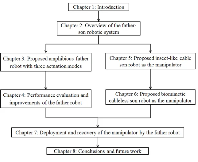
Figure 1-10 shows the structure of the thesis. Chapter 1 is the introduction. It is composed of thesis scope, literature review, research purposes, research approaches and thesis structure. In chapter 2, overview of the father-son robotic system is introduced. The father-son robotic system is composed of an amphibious father, and several micro son robots developed as the manipulators of the system. Chapter 3 introduces the proposed amphibious spherical father robot. The amphibious father robot was designed and developed with three actuation modes to adapt to various complex environments, on land and underwater. In chapter 4, the on-land and underwater performance of the father robot was evaluated. And the performance of the robot was improved, including the obstacle avoidance ability and the control of the moving direction. In chapter 5, an insect-like cable son robot was developed as the manipulator of the father-son robotic system. Chapter 6 presented a biomimetic cableless son robot employed as the manipulator. And chapter 7 presents the deployment and recovery of the manipulator of the father robot. In chapter 8, conclusions and future work were given.
34 Study on an Amphibious Father-son Robotic System
Chapter2 Overview of the father-son robotic system 35
Ph.D. thesis of Dr. Maoxun Li
Chapter 2
Overview of the father-son robotic
system
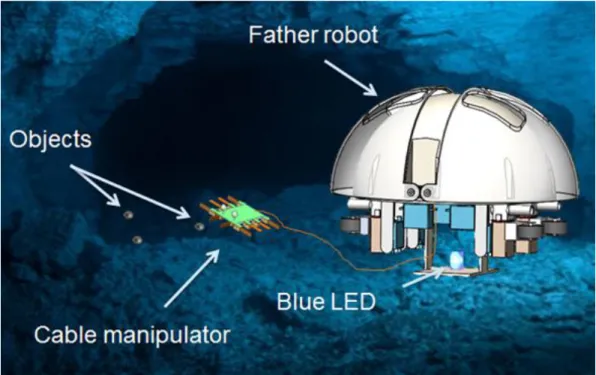
To implement the underwater intervention tasks, a father-son robotic system was proposed, which is composed of an amphibious father robot and several microrobots used as the manipulators of the system. The manipulators of the father robot include a cable son robot and a cableless son robot. The father robot with a high mobile velocity provides the power and sends control signals to the cable microrobot. And the father robot controls the cableless microrobot by the underwater optical communication system. With the ability of carrying microrobots actuated by smart actuators [23], [25], spherical robot can be employed to collect samples or carry out water-quality monitoring in a confined underwater space [19], [26]. Microrobots are used as the manipulators to grip objects underwater or a monitor to monitor the water quality and so on. The conceptual design of the father-son robotic system is shown in Figures 2-1 and 2-2.
36 Study on an Amphibious Father-son Robotic System
Figure 2- 1 The conceptual design of the father-son robotic system (cable son robot)
Figure 2- 2 The conceptual design of the father-son robotic system (cableless son robot)
Chapter2 Overview of the father-son robotic system 37
Ph.D. thesis of Dr. Maoxun Li
2.1 The amphibious spherical father robot
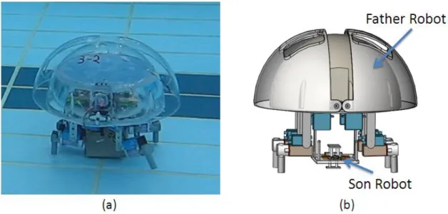
Generally, underwater vehicles need to be shipped to the operation waters and recycled after underwater tasks. Compared with underwater robots, amphibious robots can walk from the ground to the water without shipping, and vice versa [6], [7]. A novel amphibious spherical robot with transformable composite propulsion mechanisms was designed and developed, which can control and carry microrobots. The composite mechanism is designed to switch between water-jet propeller, leg and wheel. A sphere provides maximum internal space, and symmetry of the spherical shape provides superiority of flexibility and no dynamic coupling [21], [22]. Figure 2-3 shows the father-son configuration.
Figure 2- 3 Father-son robot configuration: (a) prototype of the amphibious father robot and (b) the conceptual design of the father-son
38 Study on an Amphibious Father-son Robotic System
2.2 The proposed son robots
When designing the microrobot, several constraints must be taken into account. First, as the holder on the amphibious robot for carrying microrobots has a finite size, the microrobot should be designed to be miniaturization. Second, since the father robot is a small-sized vehicle, it cannot provide too high energy for itself and the microrobots. Thus, the low-powered actuators are required for driving microrobots. Finally, in view of the implementation of the low power consumption, the microrobot should be light in weight.
According to the above restrictions, smart material-based microrobots are appropriate to be the mechanical arms of the father-son robot system. In contrast to traditional actuators, smart materials, like ionic conducting polymer film (ICPF), shape memory alloy (SMA), piezoelectric elements, and pneumatic actuator etc., can be employed as actuators directly and it is easy for them to realize the flexible movements with the advantages of small size and light weight. A fish-like biomimetic microrobot driven by SMA actuators was developed with a maximum speed of 112 mm/s [29]. And another fish-like robot used an ICPF actuator passive tail fin to mimic the swimming motion of the real fish [30]. Moreover, an ICPF actuator-based jellyfish-like robot utilized a balloon to regulate its buoyancy and an insect-like robot used ICPF actuators as legs for walking motions [23], [31].
Chapter2 Overview of the father-son robotic system 39
Ph.D. thesis of Dr. Maoxun Li
Compared with other smart materials, ICPF actuators have the advantages of compact structure, low driving voltage, and low noise, ability of driving in water, soft characteristic, and quick response properties. Therefore, ICPF actuators are more suitable to drive the son robot of the father-son robot system. As swimming motion cannot realize a comparatively precise position control, designing a legged robot as the son robot is an excellent option for underwater tasks.
To realize the underwater object recovery, two kinds of the smart actuator-based biomimetic microrobots are developed as the son robots of the father-son robotic system, which are mounted on the plastic plate in the lower hemisphere of the father robot to be used as the manipulators of the father robot. One is an ICPF-actuated eight-legged cable microrobot, the other is an ICPF actuator-based cableless microrobot. The father robot sent the control signals and power supply to the cable son robot through cables and communicated with the cableless son robot through a proposed underwater optical communication system.
2.3 Summary
In this chapter, an amphibious father-son robotic system has been introduced. The system is consisted of an amphibious father robot and two kinds of microrobots employed as the manipulators of the robotic system. The father robot was developed with three actuation modes.
40 Study on an Amphibious Father-son Robotic System
The cable son robot is controlled by the father robot through the cables; while, the cableless robot can communicate with the father robot through the underwater optical communication system.
Chapter 3 Proposed amphibious father robot with three actuation modes 41
Ph.D. thesis of Dr. Maoxun Li
Chapter 3
Proposed amphibious father robot
with three actuation modes
3.1 General design
The design concept of the amphibious spherical robot is illustrated in Fig. 1. With transformable composite propulsion mechanisms, the robot has three actuating modes: water-jet propulsion mode, quadruped walking mode and roller-skating mode. The amphibious robot is capable of movement from the water to the ground without manpower, and vice versa. Underwater microrobots with flexible movement and compact structure are carried on the amphibious robot. The amphibious robot can provide power and send signals to cable microrobot with cables and control the cableless microrobot through the underwater optical communication system. Microrobots can be controlled to collect underwater objects as a manipulator or monitor underwater environment in a restricted space.
The amphibious robot consists of a sealed transparent upper hemispheroid, two transparent quarter spherical shells that can be opened, a plastic plate for carrying the micro-robots, and four actuating
42 Study on an Amphibious Father-son Robotic System
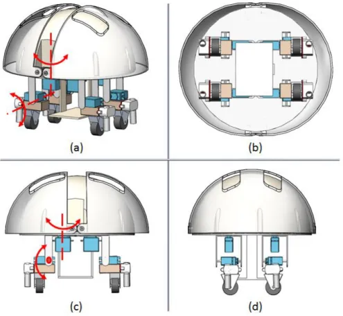
units, which are fastened to a plastic circular plate, as shown in Figure 3-1. The two quarter-spherical shells are controlled by two servomotors to open the shells by rotating them through an angle of 90º. The control circuits, power supply, and sensors are placed in the sealed upper hemispheroid, which is waterproof. The space in the lower hemisphere is connected to the outside environment via gaps on the hull. The plastic plate and actuating system are installed in the lower hemisphere. Each actuating unit consists of a water-jet propeller and two servomotors, which are perpendicular to each other, and can realize two degrees of freedom. The holes on the quarter spherical shell provide the space for the water-jet propellers to rotate to allow the robot to maneuver when it is closed. The diameter of the upper hemisphere is 234 mm, and the diameter of the lower hemisphere is 250 mm. The height of the actuating unit in the standing state is 108 mm, and it is 85 mm long.
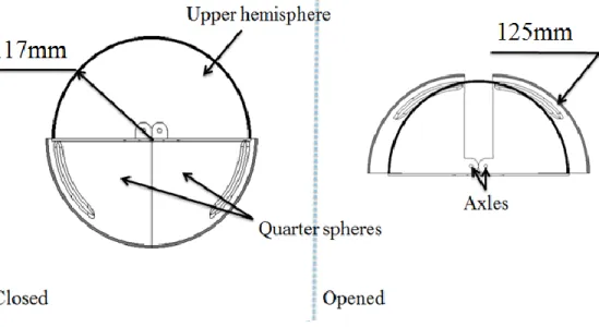
Figure 3-2 shows the opening mechanism of the amphibious robot. The quarter spherical shells are mounted on two parallel axles, which are fixed to the upper hemisphere at a distance for independent control. From Figure 3-2, we can see that this structure avoids collisions between the two quarter-spherical shells and the upper hemisphere. The two axles are actuated by two JR DS3836 servomotors.
Chapter 3 Proposed amphibious father robot with three actuation modes 43
Ph.D. thesis of Dr. Maoxun Li
Figure 3- 1 Structure of the amphibious spherical robot
44 Study on an Amphibious Father-son Robotic System
3.2 Actuation and control system
There are three actuation systems: a water-jet actuation system, a quadruped walking actuation system and a roller-skating actuation system [45]. The actuation system consists of four main units. Each unit includes a water-jet propeller, two servomotors, a passive wheel and a stainless-steel stand. The motor connected to the circular plate is controlled to move horizontally, and the motor fixed on the water-jet propeller is controlled to move vertically. Each unit has two degrees of freedom. Figure 3-3 shows the structure of the robot in three actuating modes.
3.2.1 Quadruped actuation system
The quadruped actuation was built to realize walking motion [24], [34]. Two servomotors, which are located on the surface of the plastic circular plate outside the upper hemisphere, are used to control the spherical shells.
To identify the appropriate servomotors for the legs of the robot, we carried out force analysis calculations. Figure 3-4 shows the force analysis of the robot on land. In the standing state, each vertical servomotor provides a torque 𝑴𝟏. In the walking state, each vertical servomotor of the stationary legs provides a torque 𝑴𝟐 and each horizontal servomotor of the moving legs provides a torque 𝑴𝟑. Here,
Chapter 3 Proposed amphibious father robot with three actuation modes 45
Ph.D. thesis of Dr. Maoxun Li
contact with the ground is the same. Considering that the torque on each servomotor cannot exceed the rated torque 𝑴, we arrive at the following relationships:
𝑚𝑔 = 4𝐹𝑁1 = 2𝐹𝑁2 (Eq. 2-1) 𝑀⃗⃗⃗⃗⃗ = 𝐹1 ⃗⃗⃗⃗⃗⃗ ∙ 𝑙 (Eq. 2-2) 𝑁1 𝑀⃗⃗⃗⃗⃗ = 𝐹2 ⃗⃗⃗⃗⃗⃗ ∙ 𝑙 (Eq. 2-3) 𝑁2 The condition of frictional motion of each leg without longitudinal and transversal slipping is:
|𝑀⃗⃗⃗⃗⃗ | = |𝐹 | ∙ 𝑠 < 𝜇|𝐹3 ⃗⃗⃗⃗⃗⃗ | ∙ 𝑠 (Eq. 2-4) 𝑁2 where 𝐹𝑁1 and 𝐹𝑁2 are the normal forces exerted on the surfaces, 𝐹 is the force due to friction, 𝜇 is the coefficient of friction of the contact surface, 𝑙 is the moment of the arm of the vertical motor, and 𝑠 is the moment arm of the horizontal motor.
max(𝑀1, 𝑀2, 𝑀3) < 𝑀 (Eq. 2-5) The normal force 𝐹𝑁 varies depending on the walking gait. The force 𝐹𝑁1 is the minimum force that supports the robot; when robot stands with four legs, this is given by (Eq. 2-1). When the robot walks on land, there are times when only two or three legs are in contact with the ground. The supporting force 𝐹𝑁2 is the maximum supporting
46 Study on an Amphibious Father-son Robotic System
Figure 3- 3 Structure of the robot in three actuating modes: (a) overall structure, (b) bottom view, (c) front view and (d) side view
Chapter 3 Proposed amphibious father robot with three actuation modes 47
Ph.D. thesis of Dr. Maoxun Li
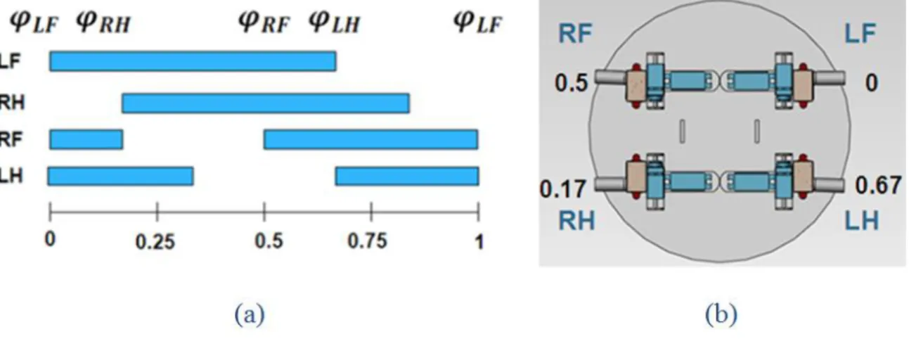
To adapt to different environments, quadruped robots with two degrees of freedom in each leg may use a number of different gaits [38]. A proper walking gait has been implemented in the spherical robot. For this walking gait, the front leg is lifted while the ipsilateral hind leg is set down, which can achieve a good stability margin. And there are times when the robot has only two legs in contact with the ground. Accordingly, the gait event sequence and the gait timing can be defined by the duty factor β and the relative phase of the left-hind leg 𝛗𝐋𝐇. The relative phases of all the legs are defined so that 𝛗𝐋𝐅 = 0 and 𝛗𝐑𝐅 = 0.5; the right-hind (RH) leg has a phase difference of 0.5 relative to the left-hind (LH) leg. Figure 3-5 (a) shows the event sequences of the first gait with a duty factor of β = 0.67. The relative phases of the legs for the first gait are shown in Figure 3-5 (b).
The velocity of the robot is related to the step size and frequency of the gait cycle, i.e.,
𝑣 = 𝑑 ∗ 𝑓 (Eq. 2-6) where v is the velocity of the robot, d is the step size of the robot, f is the frequency of one step cycle. The step size is proportional to the angle of rotation of the leg, which is the given by the angle of rotation of the horizontal motor and the duty factor of the gait-timing sequence, i.e.,
𝑑 = ( 𝜃
48 Study on an Amphibious Father-son Robotic System
where β is the duty factor of the gait-timing sequences, and θ is the rotation angle of the horizontal motor.
Substituting (Eq. 2-7) into (Eq. 2-6), we can achieve the following: 𝑣 = 0.1483 ∗ 𝜃 ∗ 𝑓/𝛽 (Eq. 2-8) which is related to the frequency and the duty factor of the gait cycle.
Figure 3- 5 Event sequences (a) and relative phases (b) of one gait cycle for the walking gait
3.2.2 Roller-skating actuation system
Roller-skating uses wheels initially to provide pushing force by exploiting high lateral ground reaction forces and subsequently to reduce friction along the direction of motion, which allows the subject to slide forward. In the moving range of legs, there are a large number of possible trajectories. In a classic roller-skating motion, the human skater pushes one leg out and then makes it get full extension. In this process, the other leg is used as a supporter with its passive wheel
Chapter 3 Proposed amphibious father robot with three actuation modes 49
Ph.D. thesis of Dr. Maoxun Li
freely rotating until the skater recovers the preceding extended leg to its starting position. The two legs drive the skater alternately and each leg pushes off the ground consistently in one direction (e.g. the right leg only moves to the right) [35].
A roller-skating gait proposed for the quadruped robot is inspired by the classic roller skating motion of human being. In the initial state of the skating motion, all the legs should keep vertical to the ground and should be aligned with the direction of motion of the robot. In the skating process, two front legs remain in contact with the ground at all times with the horizontal and vertical servo motors fixed at a constant angle and keep the rolling surface of each wheel facing forward; two rear legs implement the pushing movement periodic alternately. When one rear leg is actuated to push the ground, the rotational angle of the two servo motors of the other rear leg is fixed and the leg keeps its wheel’s rolling surface facing forward as the front legs. For the sliding forward motion, two rear legs are controlled by the robot to implement an alternately cyclical motion with at least three wheels facing forward at any one time, which indicates that the robot’s center of gravity must remain inside a polygon formed by the supporting legs.
With roller-skating gait, the front legs only have one phase, the free rolling phase; while the rear legs have three phases, including the free rolling, sliding and propulsion phases. In the free rolling phase, the leg remains stationary and the passive wheel rotates freely around the axle
50 Study on an Amphibious Father-son Robotic System
which is fixed at a right angle to the leg. In the sliding phase, the horizontal servo motor of the rear leg will rotate 60 º anti-clockwise, while the vertical motor will rotate 20 º anti-clockwise. During this period, due to the low friction generated by the rolling motion of the wheel, the friction resistance can be overlooked or ignored. In the propulsion phase, the rotational angle of the horizontal motor remains the same as the final state in the sliding phase and the vertical motor will rotate 40 º clockwise to produce driving force for the robot, as shown in Figure 3-6. Assuming that there is no slip in the propulsion phase, the friction force formed by relative motion between the moving wheel and the ground, as the driving force of the robot in roller-skating mode, can be expressed as follows:
𝑓(𝑡) = 𝐹2(𝑡) = 𝐹 ∙ 𝑐𝑜𝑠 𝜃(𝑡) = 𝑇
ℎ∙ 𝑐𝑜𝑠 𝜃(𝑡) (Eq. 2-9)
𝐹𝑟(𝑡) = 𝑓(𝑡) = 𝑇
ℎ∙ 𝑐𝑜𝑠 𝜃(𝑡) (Eq. 2-10)
where 𝑓(𝑡) is the friction force generated by the vertical servo motor, 𝑇 is the rated torque of the servo motor, ℎ is the moment arm, 𝐹𝑟(𝑡) is the driving force of the robot, 𝜃(𝑡) is the amplitude of the swing angle around the axis of vertical servo motor, 𝜃𝑚 is the maximum amplitude, and 𝜇 is the friction coefficient between the wheel and ground.
Chapter 3 Proposed amphibious father robot with three actuation modes 51
Ph.D. thesis of Dr. Maoxun Li
Figure 3- 6 Force analysis in the propulsion phase (side view). The blue arrows indicate the direction of the force applied on the ground by robot. The orange arrows indicate the direction of the force applied on
the wheel of the robot by ground
The resultant force 𝐹𝑟 is the driving force while roller-skating. However, the resultant force acting along the ground plane can be summarized as the longitudinal force to actuate the robot to slide forward and the transversal force to generate a lateral displacement as shown in Figure 3-7. Due to the presence of the transversal force, the robot will not go straight exactly. The force imposed by the left rear leg is the same with that formed by the right rear leg at any position. Consequently, the robot will move along a wave trajectory, as shown in
52 Study on an Amphibious Father-son Robotic System
frequency of the swing motion of each rear leg. Due to the symmetry, the transversal reaction force generated by the two rear legs can be counteracted after finished one-cycle sliding motion. Therefore, the robot will move to a destination right ahead. The longitudinal force and the transversal force can be obtained as follows:
𝐹𝑟1(𝑡) = 𝐹𝑟(𝑡) ∙ sin 𝛼(𝑡) (Eq. 2-11) 𝐹𝑟2(𝑡) = 𝐹𝑟(𝑡) ∙ cos 𝛼(𝑡) (Eq. 2-12) where 𝐹𝑟1(𝑡) is the driving force acting parallel to the robot’s moving direction, 𝐹𝑟2(𝑡) is the driving force acting perpendicularly to the moving direction, 𝛼 is the maximum amplitude of the swing angle around the axis of horizontal servo motor.
Utilizing alternating movements of two rear legs, the robot can realize the sliding forward motion with the rolling surfaces of the front wheels facing forward. Since the rear legs can produce an actuating force through pushing off the ground, the robot can make turns by steering the front legs. During the turning motion, the horizontal servo motors of the two front legs are controlled to rotate clockwise or anticlockwise to change the turning direction.
Chapter 3 Proposed amphibious father robot with three actuation modes 53
Ph.D. thesis of Dr. Maoxun Li
Figure 3- 7 Ground reactive force analysis on (a) left rear wheel and (b) right rear wheel while roller-skating and (c) gait cycle diagram in sliding and propulsion phases (top view). Phase 1 and 3 are sliding phases; phase 2 and 4 are propulsion phases. The legs are labeled as
follows: left fore (LF), right fore (RF), left rear (LR), and right rear (RR). The light blue rectangle indicates the driven leg moving with three degrees of freedom, while the dark blue one indicates the leg moving with passive degree of freedom. The red arrow indicates the
54 Study on an Amphibious Father-son Robotic System
Figure 3- 8 Leg trajectory when (a) roller-skating and (b) walking
3.2.3 Braking/Transformation Mechanism
From the images segmented by the level set equation, a skeletonization technique is applied to obtain the vessels centerlines. This process allows our simulator to efficiently perform collision detection and blood flow computation by supplying an abstract topological representation of the vascular network.
As we mentioned , two front legs remain their initial positions at any time while sliding and two rear legs perform the pushing movements alternately. In a classic braking motion for roller-skating, the human skaters drag the toe stop along the ground to produce a resistance along
Chapter 3 Proposed amphibious father robot with three actuation modes 55
Ph.D. thesis of Dr. Maoxun Li
the direction of motion or change their pose to a pigeon-toed pose to slow down. Since a human ankle has three active degrees of freedom, human can realize these two braking motions quickly and easily. However, it is difficult for the quadruped robot to stop with these two methods due to the wheel part only having one passive degree of freedom. Therefore, a braking mechanism is required to stop the robot instead of the traditional ways.
Adding braking equipment for each leg will cause serious weight increment and volume increases on the robot. Since the robot has a compact structure and actual torque of servo motor is limited according to the rated torque, additional braking equipment should not be carried on the robot’s legs. Accordingly, a novel braking mechanism of wheel is proposed to implement the braking motion, as shown in Figure 3-9. Using this mechanism, no more additional devices are needed for braking motion. By changing the rotational angle of the vertical servo motor, the robot can apply brake and loose brake.
Figure 3-9 (b) shows the proposed braking equipment, which is composed of a fulcrum, a spring, a plastic plate, a rigid wire and a rubber. The rough rubber is used as a brake pad to be squeezed against the wheel. The rigid wire linked to the end of the plate is connected to the vertical motor bracket, as shown in Figure 3-10 (a). When the rigid wire is in a tight state, the spring is compressed to separate the rubber from the wheel, which implements a free rolling for the passive wheel. When the rigid wire is in a loose state, the compressed spring will apply
56 Study on an Amphibious Father-son Robotic System
an elastic force on the rubber to make the rubber contact with the wheel completely, which makes the actuation unit be a leg while walking.
Figure 3- 9 Braking mechanism of the wheel: (a) overall structure and (b) cross-section diagram
Figure 3- 10 Leg-wheel hybrid actuation system: (a) overall structure, (b) front view and (c) side view
Chapter 3 Proposed amphibious father robot with three actuation modes 57
Ph.D. thesis of Dr. Maoxun Li
In order to implement the walking and roller-skating motions for the robot in the new structure at the meantime, a transformation mechanism, which can switch the robot’s locomotion between roller-skating and quadruped walking, is required. As rotating the vertical servo motor can tense and loose the rigid wire to change the state of wheel between free rolling and braking states, the proposed braking mechanism can also be used as a transformation mechanism to perform the mode switching between walking and roller-skating modes. The rotational angle of the vertical motor is in a range of 𝜃𝑚𝑖𝑛 to
𝜃𝑚𝑎𝑥 while walking and roller-skating. The initial angle 𝜃𝑖𝑛𝑖𝑡𝑖𝑎𝑙 shown in Figure 3-10 (b) indicates the initial state of the robot’s leg when roller-skating. The vertical servo motor in the initial state tenses the rigid wire just right to separate the rubber from the wheel, remaining the wheel in free rolling state. When the motor rotates anticlockwise from the initial position, the wire will be pulled tighter to loose brake as like in the initial state; when the motor rotates clockwise from the initial position, the wire will be released to apply brake.
We have mentioned that two front legs and one rear leg are in the initial state and the other rear leg implements the sliding and propulsion phases during roller-skating. In the initial state, wheels can roll freely without applying brake. In sliding phase, as the rotational angle of the motor is less than the initial angle, the wheel of active rear leg performs the free rolling motion. Additionally, in the propulsion phase, the wheel
58 Study on an Amphibious Father-son Robotic System
rotates around the axis of the vertical motor, which is perpendicular to the axle, to push off the ground to generate the driving force in two directions. In the propulsion phase, the robot will loose brake at first and then apply brake, which has no effect on the movement of the robot.
The rotational angle of the vertical motor in the initial state is 1 degree larger than 𝜃𝑖𝑛𝑖𝑡𝑖𝑎𝑙 while walking motion. The rotational angle
in walking mode is in a range of the walking initial angle to the maximum angle 𝜃𝑚𝑎𝑥. During the walking motion, all the wheels are in braking state at any time.
3.2.4 Water-jet actuation system
From the images segmented by the level set equation, a skeletonization technique is applied to obtain the vessels centerlines. This process allows our simulator to efficiently perform collision detection and blood flow computation by supplying an abstract topological representation of the vascular network.
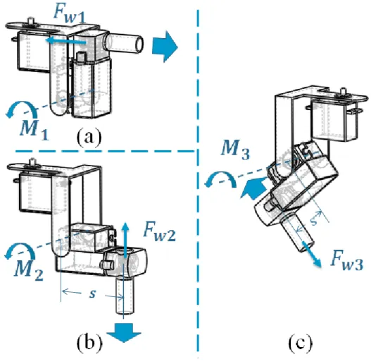
The robot is actuated by water-jet propellers when underwater [36]. By controlling the angles of the servomotors, the spray angle of the water-jet propellers can be varied to control the motion of the robot. A force analysis was carried out to assess the requirements of the servomotors on the actuator units. Figure 3-11 shows the force analysis for one actuator unit during horizontal motion, floating motion, and sinking motion. By changing the angle of the vertical motor, thrust can
Chapter 3 Proposed amphibious father robot with three actuation modes 59
Ph.D. thesis of Dr. Maoxun Li
be realized in all directions. The torque of the motor can be calculated as follows:
𝑀1
⃗⃗⃗⃗⃗ = 𝐹⃗⃗⃗⃗⃗⃗ ∙ 𝑠 = 𝐹𝑤1 ⃗⃗⃗⃗⃗⃗ ∙ 𝑠 = 𝑀𝑤2 ⃗⃗⃗⃗⃗ (Eq. 2-13) 2 𝑀3
⃗⃗⃗⃗⃗ = 𝐹⃗⃗⃗⃗⃗⃗ ∙ 𝑠 (Eq. 2-14) 𝑤3 where 𝐹𝑤1, 𝐹𝑤2, and Fw3 are the thrusts generated by the water-jet propeller, 𝑀1, 𝑀2, and 𝑀3 are the torque on the servomotor, and 𝑠 is the moment arm of the vertical motor. Appropriate servomotors were chosen by considering the maximum required torque.
To achieve the dynamic model of water-jet propeller, we build a fluid model of water-jet propeller by reference to a previous method [22], [37], as shown in Figure 3-12. The shaft of the motor, on which four blades are fixed, is perpendicular to the nozzle. Due to the small diameter of the nozzle, we can ignore the velocity difference across the nozzle. So we consider the axis flow velocity 𝑉𝑎 as a linear combination of incoming flow velocity 𝑉𝑖 and the central flow
velocity 𝑉𝑐. In Figure 3-12, Ω is the rotational velocity of motor shaft, 𝑉𝑓 is velocity of ambient flow, 𝑉𝑖 is velocity of incoming flow, 𝑉𝑜 is velocity of outlet flow, 𝜃 is incoming angle of ambient flow and 𝐷 is diameter of the nozzle. Finally, the axis flow velocity can be obtained:
𝑉𝑎 = 𝑘1𝑉𝑖 + 𝑘2𝑉𝑐
60 Study on an Amphibious Father-son Robotic System
𝑉𝑐 = 1
2𝐷Ω
Assuming that the flow is incompressible, according to the equation of continuity, we know that the volume of incoming flow must be equal to the outlet flow, as shown in (Eq. 2-16).
𝜌𝑎𝑉𝑎𝐴𝑎 = 𝜌𝑜𝑉𝑜𝐴𝑜 (Eq. 2-16) where: the fluid density 𝜌𝑎 and 𝜌𝑜 are equal to 𝜌, the cross-section of the nozzle 𝐴𝑎 is equal to 𝐴𝑜.
Hence, we arrive at the following relationship:
𝑉𝑎 = 𝑉𝑜 (Eq. 2-17)
The thrust of the water-jet propeller in two directions can be calculated as (Eq. 2-18) and (Eq. 2-19) respectively.
𝐹𝑤1 = 𝐹𝑤2 = 𝜌𝐴𝑉𝑎2 (Eq. 2-18)
𝐹𝑤3 = 𝜌𝐴𝑉𝑐2 (Eq. 2-19)
By substituting (Eq. 2-15) in (Eq. 2-18) and (Eq. 2-19) respectively, the thrust generated by water-jet propeller can be computed as (Eq. 2-20) and (Eq. 2-21). 𝐹𝑤1 = 𝐹𝑤2 = 1 4ρπ𝐷 2(𝑘 12𝑉𝑖2 + 𝑘1𝑘2𝜋𝐷𝑉𝑖 + 1 4𝑘2 2𝐷2Ω2) (Eq. 2-20) 𝐹𝑤3 = 1 16ρπ𝐷 4Ω2 (Eq. 2-21)
![Figure 1- 4 AmphiHex-I developed by University of Science and Technology of China [7]](https://thumb-ap.123doks.com/thumbv2/123deta/5737918.1020699/28.918.181.725.573.936/figure-amphihex-i-developed-university-science-technology-china.webp)
![Figure 1- 6 AZIMUT [14]](https://thumb-ap.123doks.com/thumbv2/123deta/5737918.1020699/31.918.181.746.696.960/figure-azimut.webp)
![Figure 1- 9 The main vehical equipped with highly maneuverable agent ROV [19]](https://thumb-ap.123doks.com/thumbv2/123deta/5737918.1020699/33.918.177.757.506.933/figure-main-vehical-equipped-highly-maneuverable-agent-rov.webp)