Effect of carrier gas on anode performance of Si
thick-film electrodes prepared by gas-deposition
method
Hiroyuki Usui, Yusuke Kiri, and Hiroki Sakaguchi*
Department of Chemistry and Biotechnology, Graduate School of Engineering, Tottori University 4-101 Minami, Koyama-cho, Tottori 680-8552, Japan
*Corresponding author. Tel./Fax: +81-857-31-5265; e-mail: [email protected]
Keywords: Si anode; Thick-film electrode; Gas-deposition method; Carrier gas; Li-ion battery
Abstract
Silicon thick-film electrodes for Li-ion battery anodes were prepared by a gas-deposition method using carrier gases of Ar and He. We investigated the effect of the carrier gases on film morphology and anode performance. The root mean square roughness of the films formed by He gas was twice larger than that formed by Ar gas. The Si electrode obtained by He gas exhibited a larger film thickness up to 4 µm, a higher initial capacity of 2280 mA h g-1, and larger capacities until 40th cycle compared with other electrodes. The better performance is probably attributed to a formation of many interspaces within the thick film. It is suggested that these interspaces enhanced contact area between active material and electrolyte, which enabled an efficient alloying/dealloying reaction of Li–Si.
1. Introduction
Li-ion batteries are the most important energy-storage devices developed in the past two decades, and are applied not only to portable electronic devices but also to electric vehicles and stationary battery systems. These next-generation batteries require a higher energy density and a longer life for charge−discharge cycle in comparison with those in practical use. The theoretical capacity is, however, only 372 mA h g−1 for a graphite anode which is most generally used in the battery at present. In recent years, many researchers have intensively studied some elemental materials which show alloying/dealloying reactions with Li at low electrode potentials, resulting in reversible Li insertion/extraction as anode materials.
Silicon can react with Li to form binary alloys with four kinds of Li/Si ratios such as Li12Si7
(Li1.71Si), Li7Si3 (Li2.33Si), Li13Si4 (Li3.25Si), and Li22Si5 (Li4.4Si) at high temperature of 415oC [1,2].
On the other hand, it has been recently reported that the crystal phase is changed from Si to Li15Si4
(Li3.75Si) during an electrochemical lithiation at room temperature [3-10]. The Li22Si5 and Li15Si4
phases exhibit huge theoretical capacities of approximately 4200 and 3580 mA h g−1, which are about ten times larger than that of graphite. In addition, Si is abundant, less expensive, and nontoxic element. Thus, Si has attracted much attention as next-generation anode materials. A practical use of Si for the anodes has been, however, disturbed by some critical disadvantages of its low intrinsic electrical conductivity, a low diffusion coefficient of Li in Si (10-14–10-12 cm2 s-1 [11-13]), and a drastic change of specific volume during the alloying/dealloying reactions. The volumetric change ratios per Si atom from Si to Li22Si5 and Li15Si4 corresponds to be 410% [14-16] and 380% [10],
which causes an accumulation of stress and a pulverization of the active materials, thereby inducing losses of an electrical contact between the materials and the current collector. Therefore, Si anodes show a rapid capacity fading by repeating charge–discharge cycles. Many attempts have been made to improve electrode performance of Si anodes by various approaches, which can be basically
1. Pure Si nano-scale powder. 2. Si dispersed in an inactive matrix. 3. Si dispersed in an active matrix. 4. Si anodes with a functional binder. 5. Pure Si thin films.
Among the five approaches, pure Si thin films are relatively suitable to study their fundamental properties and mechanism of improved performance because we can eliminate the extrinsic influence on anode properties originated from the conductive matrix, the binder, and the nanosize effect. However, the thin film with a smaller thickness than 100 nm is inherently a favorable structure and thus shows good cycling performance since the film volume can be easily change in the perpendicular direction to the film surface due to its smaller thickness. We, consequently, believe that Si thick-film electrodes with a larger thickness than 1 µm should be evaluated to discuss the cycling performance for a more practical study. For fundamental studies of Si film electrodes, many researchers have investigated the properties of Si films prepared by vacuum evaporation [18,19], pulsed laser deposition [20-22], radio frequency magnetron sputtering [23,24], and chemical vapor deposition [25]. High quality films can be easily obtained by these methods, whereas it is difficult to form thick film with more than 1 µm in thickness. Another method to prepare thick films is required for practical researches of anodes in Li-ion batteries.
Advantages of a gas-deposition (GD) method for thick-film anodes of Li-ion batteries have been intensively demonstrated in our previous studies [26-36]. This is also called an aerosol deposition method, which has been developed by Akedo et al. for ceramic thick films of piezoelectric devices [37-40]. In this method, an aerosol consisting of raw powder particles and a carrier gas is sprayed from a nozzle onto a substrate to form thick films. The formation mechanism of thick films has been suggested as follows: Particles of source material powder are accelerated to high speed of about 150–500 m s-1 by carrier gases ejected from the nozzles [39,40]. By the impact of collision between
the particles and substrates, the particles undergo fracture and plastic deformation. Fresh surface of the particles is generated by the fracture, and it faces the surface of other particles. An interdiffusion of atoms occurs on the interface because of the high impact energy, resulting in a strong adhesion of the particles even at a room temperature. During the solidification, an interspace between the particles is formed in the film. This unique phenomenon was named "room temperature impact consolidation" [39,40], which has various advantages including (i) the strong adhesion between the active material particles as well as between the particles and the substrate, (ii) the nearly unchanging composition in the thick film formed without vaporization process of the particles, and (iii) the formation of interspaces between particles, which is a favorable structure to release the stress induced by the volumetric change of the active material particles.
Carrier gas is one of the most important preparation conditions of the GD method. It has been reported that an aerosol velocity is increased with decreasing molar weight of carrier gas, and that various physical properties of obtained thick films depend on gas velocity [37-40]. In the GD method for thick-film anodes, we can expect that the film morphology can be controlled to improve the anode performance by changing the carrier gas. In this study, we prepared Si thick-film electrodes by the GD method using different carrier gases of He and Ar, and investigated the effect of the film morphology on their anode performance.
2. Experimental details
Gas-deposition was performed in a vacuum chamber with a guide tube. Nozzles with 0.3 and 0.8 mm in diameters were connected at the end of the guide tube. A current collector of Cu foil substrate with 20 µm in thickness was set at a distance of 10 mm from the nozzle. Carrier gases used were Ar or He (a purity of 99.9999%) with a differential pressure of 7×10⁵ Pa. After the chamber was
tube, and instantly gushed from the nozzle onto the Cu substrate. Si thick films with a deposition weight of 6–17 µg were formed on the substrates. The deposition area of the films was measured to be 8.0–22.1 mm2 as summarized in Table 1. The surface morphology of as-prepared Si thick films
was observed by using a confocal scanning laser microscope (CSLM, VK-9700, Keyence) and a field emission scanning electron microscope (FE-SEM, JSM-6701F, JEOL Ltd.). For cross-sectional specimens for FE-SEM observation, Si thick films were embedded into a thermoset epoxy resin. After the thermoset, the Si films with the resin were sliced and were mechanically polished. The cross-sectional structure and its elemental distribution were evaluated by the FE-SEM and an energy dispersive X-ray spectroscope (EDS, EDS-54033MCK, JEOL Ltd.) operating at an accelerating voltage of 5 and 15 kV, respectively. The elemental mapping was carried out by characteristic X-ray of Si Kα for the cross-section.
Electrochemical measurements were carried out with a beaker-type three-electrode cell. The working electrodes were the obtained thick-film electrodes. Both counter and reference electrodes were 1-mm-thick Li metal sheets (Rare Metallic, 99.90%). We used LiClO4-dissolved in propylene
carbonate (PC; C4H6O3, Kishida Chemical Co., Ltd.) at concentration of 1.0 M as the electrolyte.
Constant current charge–discharge tests were performed using an electrochemical measurement system (HJ-1001 SM8A, Hokuto Denko Co., Ltd.) under a constant current density of 1.0 A g-1 (C
rate: 0.25C) at 303 K with the cutoff potentials set as 0.005 V vs. Li/Li+ for charge (Li-insertion) and 2.000 V vs. Li/Li+ for discharge (Li-extraction).
3. Results and Discussion
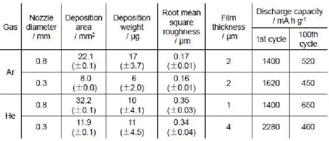
Table 1 summarizes the deposition area and the deposition weight of Si thick-film electrodes prepared by the GD method under the different conditions, the nozzle diameters of 0.3 and 0.8 mm and the carrier gases of Ar and He. The values in the parentheses in the table indicate standard deviation of each physical quantity. In each carrier gas, the deposition area was reduced by
decreasing the nozzle diameter. The deposition area was enlarged by changing carrier gas from Ar to He. We consider that the He aerosol was ejected from the nozzle with a broader angle because He gas has a smaller coefficient of viscosity (1.96×10⁻⁵ Pa s) in comparison with Ar gas (2.22×10⁻⁵ Pa s).
In proportional to the deposition area, the deposition weight in case of Ar gas was obviously decreased by narrowing the nozzle from 0.8 to 0.3 mm. On the other hand, the deposition weight of the films obtained by He gas was not so changed by narrowing the nozzle though the deposition area of the film in case of 0.3 mm nozzle is three times less than that in case of 0.8 mm. This indicates that the former has much larger film thickness compared with the latter.
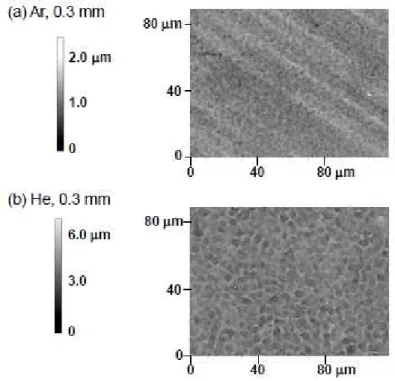
Figure 1 depicts surface morphologies observed by the confocal scanning laser microscope for the Si thick-film electrodes prepared by using the nozzle with 0.3 mm in diameter. The Si electrode prepared by He gas has a more bumpy surface. We evaluated a root mean square roughness (Rrms) of
the films to quantitatively discuss the surface morphology. The Rrms has been listed in Table 1. In
both cases of the nozzle diameters, Rrms in case of He was almost two times larger than that in case of
Ar. This roughened surface appears to be caused by a higher velocity of the aerosol containing He gas. In this study, it is difficult to estimate the aerosol velocity because the internal structures of the nozzle and the guide tube are complex. However, a suitable velocity to solidify a source powder has been reported to be typically 150–500 m s-1 [39,40]. Thus, the aerosol velocity in this study is
expected to be a comparable value. An aerosol has been confirmed to accelerate with decreasing a molar weight of carrier gas [39,40]. A gas velocity of isentropic flow through a nozzle generally increases in inverse proportion to the gas density [41]. It is therefore considered that the velocity of He aerosol is about ten times higher than that of Ar aerosol because the gas densities of He and Ar are 0.179 and 1.784 kg m-3, respectively. The higher impact energy of He aerosol possibly makes the film surface more rough.
The Si electrodes prepared by Ar and He through the nozzle of 0.8 mm showed similar surface morphologies and Rrms values. Consequently, we will hereafter focus the difference in the film
structure obtained by using the nozzle of 0.3 mm.
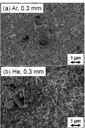
Figure 2 shows surface FE-SEM images of the Si electrodes prepared by Ar and He through the 0.3 mm nozzle. We can recognize aggregated particles with an angular shape, which is originated from the morphology of the Si source powder, for both Si electrodes. For the electrode formed by He, large particles with a size exceeding 1 µm were also observed. The electrode prepared by He shows a rougher surface morphology than that by Ar, which is supported by the Rrms values of the laser
microscopy measurements.
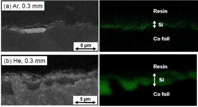
Figure 3 displays cross-sectional FE-SEM images and corresponding EDS mapping results of Si Kα for the electrodes. Although the film thickness was not uniform in the films, we can estimate the thickness of Si thick films by a combination of the images and the mapping results. The maximum thicknesses were found to be 1 and 4 µm in case of Ar and He gas through the nozzle of 0.3 mm. On the other hand, no significant difference in the maximum thicknesses owing to the carrier gas was found for the Si films formed by using the nozzle of 0.8 mm, and the thickness was 2 µm irrespective of carrier gas. These thicknesses are summarized in Table 1. Elemental Si is a very hard material with Vickers hardness of about 1000, indicating that it is difficult to prepare a thick film from Si powder with a thickness more than 1 µm without any binders. It is a noteworthy that we could increase twice the film thickness only by changing the carrier gas from Ar to He in this study, whereas we have previously used Ar carrier gas [26-36]. In contrast, we obtained a smaller thickness up to 1 µm by He gas and the wider nozzle diameter of 0.8 mm. In this case, a deposition weight per unit area was probably smaller because the He aerosol was ejected from the nozzle with a broader angle.
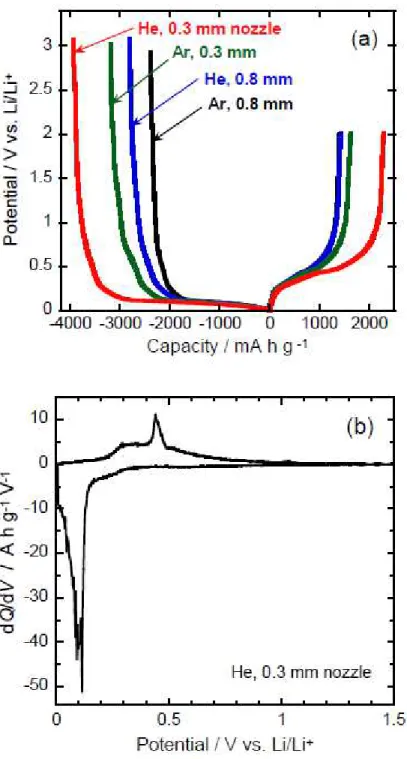
Figure 4(a) is potential profiles at the first charge–discharge cycle of the all thick-film electrodes prepared in this study. The four electrodes behaved very alike. The potentials of the all electrodes
steeply dropped to 0.1 V vs. Li/Li+, and then those follows plateaus in the charge process
(Li-insertion). In the discharge (Li-extraction) process, we can see two-stage plateaus at 0.25–0.5 V vs. Li/Li+. These potential plateaus are attributed to the alloying/dealloying reactions of Li–Si. In
order to discuss the electrode reactions, dQ/dV was calculated from numerical data of the capacities
Q and the electrode potentials V in Fig. 4(a). In case of the electrode obtained by He gas and 0.3 mm
nozzle, the dQ/dV vs. the potential plots is illustrated as a differential capacity curve in Fig. 4(b). In the cathodic profile, a large peak and a broad peak appeared at 0.1 V and 0.2 V vs. Li/Li+. In the
anodic profile, we confirmed a broad peak at around 0.3 V and a sharp peak at 0.43 V vs. Li/Li+. The other Si electrodes also exhibited similar profiles. These peak positions basically correspond to the values previously reported for Si film electrodes [22]. It has been recently revealed that an electrochemical solid-state amorphization and a two-step phase transformation take place in the first lithiation process [7-10]. Crystalline Si firstly undergoes an amorphization process to form amorphous lithium–silicon (LixSi), which then crystallizes to Li15Si4 upon full lithiation [8]. In
delithiation process, the crystalline Li15Si4 phase is delithiated to amorphous Si [8]. We consider that
the cathodic and anodic peaks in Fig. 4(b) possibly originate from the phase transformation. We can thus conclude that the obtained Si thick-film electrodes exhibited a reversible reaction of Li-insertion/extraction without a side reaction such as a successive decomposition of the electrolyte in every case.
Figure 5 shows the discharge capacities of the Si thick-film electrodes as a function of cycle number. At the first cycle, comparable capacities of 1400–1620 mA h g-1 were obtained for the three Si electrodes except for the electrode prepared by He gas and 0.3 mm nozzle. The capacities of the three electrodes were monotonically decreased with increasing the cycle number, and reached 450–650 mA h g-1 at 100th cycle. By contrast, the electrode formed by He gas and 0.3 mm nozzle
exceeded the other electrodes' capacities during initial 40 cycles. It should be noted that the electrode has a rough surface and the largest film thickness as summarized in Table 1.
The origin of the considerably enhanced capacities until 40th cycle can be explained by an increasing of contact area between the Si active material and the electrolyte. The Si electrodes formed by He gas have higher surface roughness, which indicates a formation of many interspaces within these thick films. This allows the contact area to increase so that the alloying/dealloying reactions can effectively occur. A mechanical durability of thick-film electrodes is also important to enhance their capacities. At the first charge (lithiation) process, pulverization and capacity decay probably start to happen because of the significant volume expansion of Si active material. Consequently, Si electrodes require a high mechanical durability to show larger charge/discharge capacities from the first cycle. A flux of He carrier gas from 0.3-mm nozzle can be concentrated into smaller area on the substrate due to the narrower nozzle in comparison with 0.8-mm nozzle. The concentrated aerosol gives high impact energy and makes the Si particles stick to each other in the film. The electrode prepared using He from 0.3-mm nozzle possibly has a higher mechanical durability, and therefore exhibited larger charge/discharge capacities than that from 0.8 mm-nozzle. Unfortunately, we could not avoid the pulverization and the capacity fading in any electrodes owing to silicon's volumetric change during alloying/dealloying reactions of Li–Si. We believe that the capacity fading can be drastically suppressed in composite thick-film electrodes consisting of Si and other materials because we have demonstrated that the other materials compensate silicon's disadvantages in the composite electrodes prepared by the GD using Ar carrier gas [27-34,36]. In the near future, we will therefore apply the GD method using He carrier gas for the composite thick-film anodes in order to prepare innovative electrodes with excellent performance and a large film thickness.
In this paper, we have dealt Si thick-film electrodes prepared the gas-deposition method using carrier gasses of Ar and He through the nozzle of 0.3 or 0.8 mm in diameters, and have investigated the effect of the film morphology on their electrochemical performance as an anode of Li-ion batteries. The root mean square roughness of the films formed by He gas was twice larger than that formed by Ar gas. Among them, the Si electrode prepared by He gas and 0.3 mm nozzle exhibited the largest film thickness of 4 µm, the highest initial discharge capacity of 2280 mA h g-1, and the
larger discharge capacities until 40th cycle. The better performance is probably attributed to a formation of many interspaces within the thick films. This allows the contact area between the Si active material and the electrolyte to increase significantly, which leads that the alloying/dealloying reactions can effectively occur.
Acknowledgments
This work was supported in part by the Li-EAD program of the New Energy and Industrial Technology Development Organization (NEDO) of Japan. This work has been partially supported by a Grant-in-Aid for Scientific Research from the Ministry of Education, Culture, Sports, Science and Technology (MEXT) of Japan. We would like to thank the reviewer for his/her helpful comments.
References
[1] C. J. Wen, R. A. Huggins, J. Solid State Chem., 37 (1981) 271.
[2] B. Gao, S. Sinha, L. Fleming, O. Zhou, Adv. Mater., 13 (2001) 816.
[3] T. D. Hatchard and J. R. Dahn, J. Electrochem. Soc., 151, (2004) A838.
[4] M. N. Obrovac and L. Christensen, Electrochem. Solid-State Lett., 7 (2004) A93.
[5] M. N Obrovac. and L. J. Krause, J. Electrochem. Soc., 154 (2007) A103.
[6] J. Y. Kwon, J. H. Ryu, S. M. Oh, Electrochim. Acta, 55 (2010) 8051.
[7] B. Key, M. Morcrette, J.-M. Tarascon, C. P. Grey, J. Am. Chem. Soc., 133 (2011) 503.
[8] X. H. Liu, L. Q. Zhang, L. Zhong, Y. Liu, H. Zheng, J. W. Wang, J.-H. Cho, S. A. Dayeh, S. T. Picraux, J. P. Sullivan, S. X. Mao, Z. Z. Ye, J. Y. Huang, Nano Lett., 11 (2011) 2251.
[9] X. H. Liu, H. Zheng, L. Zhong, S. Huang, K. Karki, L. Q. Zhang, Y. Liu, A. Kushima, W. T. Liang, J. W. Wang, J.-H. Cho, E. Epstein, S. A. Dayeh, S. T. Picraux, T. Zhu, J. Li, J. P. Sullivan, J. Cumings, C. Wang, S. X. Mao, Z. Z. Ye, S. Zhang, J. Y. Huang, Nano Lett., 11 (2011) 3312.
[10] X. H. Liu, L. Zhong, S. Huang, S. X. Mao, T. Zhu, J. Y. Huang, ACS Nano, 6 (2012) 1522.
[11] N. Ding, J. Xu, Y. X. Yao, G. Wegner, X. Fang, C. H. Chen, I. Lieberwirth, Solid State Ionics, 180 (2009) 222.
[12] J. Xie, N. Imanishi, T. Zhang, A. Hirano, Y. Takeda, O. Yamamoto, Mater. Chem. Phys., 120 (2010) 421.
[13] G. Zhao, Y. Meng, N. Zhang, K. Sun, Mater. Lett., 76 (2012) 55.
[15] H. Kim, C.-Y. Chou, J. G. Ekerdt, G. S. Hwang, J. Phys. Chem. C, 115 (2011) 2514.
[16] H. Usui, Y. Yamamoto, K. Yoshiyama, T. Itoh, and H. Sakaguchi, J. Power Sources, 196 (2011) 3911.
[17] U. Kasavajjula, C. S. Wang, A. J. Appleby, J. Power Sources, 163 (2007) 1003.
[18] S. Ohara, J. Suzuki, K. Sekine, T. Takamura, J. Power Sources, 119–121 (2003) 591.
[19] T. Takamura, S. Ohara, M. Uehara, J. Suzuki, K. Sekine, J. Power Sources, 129 (2004) 96.
[20] M. S. Park, G. X. Wang, H. K. Liu, S. X. Dou, Electrochimica Acta, 51 (2006) 5246.
[21] N. Kuwata, R. Kumar, K. Toribami, T. Suzuki, T. Hattori, J. Kawamura, Solid State Ionics, 177 (2006) 2827.
[22] H. Xia, S. Tang, L. Lu, Mater. Res. Bull., 42 (2007) 1301.
[23] L. B. Chen, J. Y. Xie, H. C. Yu, T. H. Wang, J. Appl. Electrochem., 39 (2009) 1157.
[24] T. Moon, C. Kim, B. Park, J. Power Sources, 155 (2006) 391.
[25] T. L. Kulov, A. M. Skundin, Y. V. Pleskov, E. I. Terukov, O. I. Kon’kov, J. Electroanal. Chem., 600 (2007) 217.
[26] H. Sakaguchi, T. Toda, Y. Nagao, T. Esaka, Electrochem. Solid-State Lett., 10 (2007) J146.
[27] T. Iida, T. Hirono, N. Shibamura, H. Sakaguchi, Electrochemistry, 76 (2008) 644.
[28] H. Sakaguchi, T. Iida, M. Itoh, N. Shibamura, T. Hirono, IOP Conf. Series: Mater. Sci. Eng., 1 (2009) 012030.
[31] H. Usui, M. Shibata, K. Nakai, H. Sakaguchi, J. Power Sources, 196 (2011) 2143.
[32] H. Usui, K. Meabara, K. Nakai, H. Sakaguchi, Int. J. Electrochem. Sci., 6 (2011) 2246.
[33] H. Usui, N. Uchida, H. Sakaguchi, J. Power Sources, 196 (2011) 10244.
[34] H. Usui, T. Kono, H. Sakaguchi, Int. J. Electrochem. Sci., 7 (2012) 4322.
[35] H. Usui, T. Masuda, H. Sakaguchi, Chem. Lett., 41 (2012) 521.
[36] H. Usui, N. Uchida, H. Sakaguchi, Electrochemistry, 80 (2012) in press.
[37] J. Akedo and M. Lebedev, Jpn. J. Appl. Phys., 38 (1999) 5397.
[38] J. Akedo and M. Lebedev, Jpn. J. Appl. Phys., 40 (2001) 5528.
[39] J. Akedo, J. Am. Ceram. Soc., 89 (2006) 1834.
[40] J. Akedo, J. Thermal Spray Tech., 17 (2008)181.
Table 1. Summary of film structure and anode performance for Si thick-film electrodes prepared by gas-deposition method in different conditions, carrier gas and nozzle diameter. Values in parentheses indicate standard deviation of each physical quantity.
Fig. 1. Surface morphology observed by confocal scanning laser microscope for Si thick-film electrodes formed by using (a) Ar and (b) He gases through nozzle with 0.3 mm in diameter.
Fig. 2. Surface FE-SEM images of Si thick-film electrodes formed by using (a) Ar and (b) He gases through nozzle with 0.3 mm in diameter.
Fig. 3. Cross-sectional FE-SEM images and corresponding EDS mapping results of SiKa for Si thick-film electrodes formed by using (a) Ar and (b) He gases through nozzle with 0.3 mm in diameter.
Fig. 4. (a) Initial charge-discharge curves of Si thick-film electrodes prepared by using different carrier gases and nozzles. (b) Differential capacity curve of Si thick-film electrode prepared by using He and 0.3 mm nozzle.
Fig. 5. Cycling performance of Si thick-film electrodes prepared by gas-deposition method using different carrier gases and nozzles of 0.3 and 0.8 mm in diameters.
Figure captions
Table 1. Summary of film structure and anode performance for Si thick-film electrodes prepared by gas-deposition method in different conditions, carrier gas and nozzle diameter. Values in parentheses indicate standard deviation of each physical quantity.
Fig. 1. Surface morphology observed by confocal scanning laser microscope for Si thick-film electrodes formed by using (a) Ar and (b) He gases through nozzle with 0.3 mm in diameter.
Fig. 2. Surface FE-SEM images of Si thick-film electrodes formed by using (a) Ar and (b) He gases through nozzle with 0.3 mm in diameter.
Fig. 3. Cross-sectional FE-SEM images and corresponding EDS mapping results of SiKa for Si thick-film electrodes formed by using (a) Ar and (b) He gases through nozzle with 0.3 mm in diameter.
Fig. 4. (a) Initial charge-discharge curves of Si thick-film electrodes prepared by using different carrier gases and nozzles. (b) Differential capacity curve of Si thick-film electrode prepared by using He and 0.3 mm nozzle.