Anode Properties of Ru-Coated Si Thick Film
Electrodes Prepared by Gas-Deposition
Hiroyuki Usui, Yuta Kashiwa, Takahisa Iida, and Hiroki Sakaguchi*
Department of Chemistry and Biotechnology, Graduate School of Engineering, Tottori University 4-101 Minami, Koyama-cho, Tottori 680-8552, Japan
*Corresponding author: phone/fax: +81-857-31-5265; e-mail: [email protected]
Abstract
Thick film electrodes consisting of Ru and Ru-coated Si particles were fabricated by a gas-deposition method and evaluated their electrochemical properties of anodes for Li rechargeable battery. The discharge capacity of the Ru electrode at 1000th cycle is approximately 400 mAh g-1. The result showed that the electrode reaction is based on the redox reaction of RuO2 which was
formed on the Ru surface during the charge-discharge processes. By coating Si particles with Ru using an electroless deposition technique, we obtained an electrode with remarkable discharge capacity of 570 mAh g-1 at 1000th cycle. The reason for the improvement in the electrode performance appears to result from the fact that the Ru electrode exhibits excellent cycleability itself and the Ru coated on Si reduces the stress generated by the immense volumetric changes occurring in the Si particles.
1. Introduction
Lithium ion battery is suggested to remain the most useful types of rechargeable batteries from the point of view of the potential size of their theoretical energy density. However, as ever higher capacities are intensively pursued, oxides and metal-based materials are actively being researched as high-capacity substitutes for carbon-based materials. Among these, Balaya et al. have reported that a slurry electrode of ruthenium oxide (RuO2) exhibits a high capacity of 1130 mAh g-1 and a high
coulombic efficiency above 98% at the first cycle [1]. They also revealed that RuO2 forms Ru/Li2O
nanocomposite during the charge process, and that Ru/Li2O shows reversible electrode reactions of
oxidation and reduction which are significantly different from other oxide materials [1,2]. During the charge-discharge process, the RuO2 is completely reduced to a metallic state forming nanoparticles
embedded in the Li2O matrix [1,3,4]. The electrochemically-reversible process is called “conversion
reaction” [5-7].
Silicon has a great potential as an anode of Li ion battery due to its larger theoretical capacity of about 4200 mAh g-1 which is estimated for fully lithiated Li-Si alloy of Li4.4Si. However, the Si
electrode has a critical problem owing to volume expansion and shrinkage during the alloying and de-alloying processes [8-10]. It is difficult to maintain the reversible reaction because the volume changes cause a destruction of the electrodes materials and a degradation of the electric contact. A gas-deposition technique is well known as a method of thick film formation for various applications due to its advantages of low cost, low-temperature process, fast deposition rate, and controlling of surface morphology [11,12]. In particular, porous films with higher surface area can be easily fabricated by this technique, which are expected to be utilized for electrode materials because an electrochemical reaction between the electrodes and electrolyte is more activated. We have developed the gas-deposition technique to fabricate electrode materials for Li ion battery, and have evaluated electrochemical properties of the fabricated electrodes [13-16].
In this study, we firstly prepared thick film electrodes of Ru and RuO2 by the gas-deposition,
respectively. Their electrochemical properties were evaluated to investigate Li-storage mechanism of those electrodes. Next, in order to realize new electrodes which combine advantageous capacity of Si and cycleability of Ru, we synthesized a composite material consisting of Ru and Si by coating of Ru on the surface of Si particle using an electroless deposition (ELD) method. We prepared thick film electrodes of Ru-coated Si by the gas-deposition, and investigated an electrochemical performance of the Ru-coated Si thick film electrodes.
2. Experimental
By using ELD technique, Ru-coated Si powder was synthesized in an aqueous solution of 0.2 mol/L(M) potassium hydroxide (KOH). Firstly, ruthenium chloride hydrate (RuCl3·nH2O, n:1~3,
Kishida Chemical Co., Ltd.) was dissolved in the KOH solution. Commercial Si powder (Wako pure chemical Industries, Ltd., 99%, size: 0.1~100 µm) was also added in the solution with stirring, and then sodium boron hydride (NaBH4) was added as a reducing agent to the solution. By the stirring
for 30 minutes, RuCl3 was reduced in the solution and elemental Ru layer was coated on the Si
powder. On the assumption of uniformly-coating of Ru on Si particles, the thickness of the coated-Ru layer was estimated to be around 1 nm. However, Ru-coating on Si is actually inhomogeneous. This indicates that the coated thickness is larger than 1 nm. The composition ratio of obtained Ru-coated Si powder was studied by inductively coupled plasma atomic emission spectroscopy (ICP-AES), which revealed that the radio Ru:Si is 6:94 wt%. The crystal structure of the Ru-coated Si powder was investigated by using an X-ray diffractometer (XRD-6000 Shimadzu Co., Ltd.).
The thick film electrodes were prepared on a Cu-rolled foil (20 µm thickness; 99.9%, Nilaco Co., Ltd.) substrate set up in the evacuated chamber equipped with a guide tube by the gas-deposition using various source materials. In this study, the source materials were the
commercial Si powder, Ru and RuO2 powders (Sumitomo Metal Industries Ltd.), Sn powder(Nilaco
Co., Ltd.), and Ru-coated Si powder prepared by the ELD method. An aerosol consisting of an argon gas (differential pressure 6×10⁵ Pa) and the powder of the source mateirals was generated in the
guide tube, and gushed toward the Cu substrate from a nozzle with a diameter of 0.8 mm. Further detailed conditions of the gas-deposition have been described in our previous papers [13-16]. The deposition weight was 21 ~ 407 µg. The surface morphology and element distribution were observed using scanning electron microscope (SEM, JSM-5200; JEOL Ltd.) and energy dispersive X-ray analysis (EDX, EDS-54033MCK; JEOL Ltd.). The film thickness of the electrodes was found to be
ca. 3 µm by cross-sectional SEM observations.
Electrochemical measurements were carried out with a beaker-type three-electrode cell. The working electrodes used were the thick film electrodes of the deposited Ru, RuO2, Sn, Si, and
Ru-coated Si on the Cu substrates. Both counter and reference electrodes were Li metal sheets (Rare Metallic, 99.90%) with the thickness of 1 mm. As an electrolyte, we used 1 M LiClO4-dissolved
propylene carbonate (PC, Kishida Chemical Co., Ltd.). In the case of the Ru film electrode, we carried out the measurements using LiPF6 (Kishida Chemical Co., Ltd.) as electrolyte and a mixed
solution of EC (ethylene carbonate) and DEC (diethyl carbonate) with 1:1 v/v% for comparison. The cell performances were evaluated by a galvanostatic method at 303K between 3.400 and 0.005 V.
3. Results and Discussion
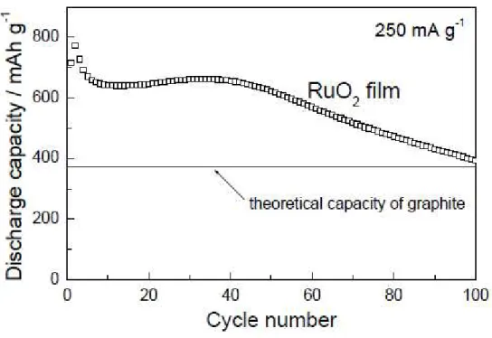
Figure 1 shows a dependence of discharge (Li-extraction) capacity on cycle numbers for RuO2
thick film electrode prepared by gas-deposition. The charge-discharge measurements were carried out in the electrolyte solution of PC containing LiClO4. The RuO2 electrode exhibited a discharge
capacity higher than the theoretical capacity of graphite electrode even at 100th cycle. The retention of the initial discharge capacity at the 15th cycle was 62% in the case of RuO2 slurry electrode
much higher retention of 89% without any conductive materials and binders, which clearly shows a remarkable improvement for the discharge capacity decay. We believe the gas-deposition method has a great advantage in the improvement. We consider the reason of the improvement is related to the gas-deposition process in which the particles of active materials gushed to the Cu substrate. In the process, the active material particles strongly stuck each other, and were partially embedded in the substrate. We are suggesting that these phenomena can suppress a breakup and an electrical isolation of the active materials caused by a volumetric change. This proves that the gas-deposition method is very effective for the production of electrodes. It has been pointed out that electrode reaction of RuO2 on Li insertion and extraction can be described by the following two-step reactions
[1]:
RuO2 + 4Li+ + 4e- ⇄ Ru + 2Li2O (1)
Li+ + e- + Ru/Li2O ⇄ Li/Ru/Li2O (2)
However, no detailed examination has been performed with respect to equation (2) which corresponds to elemental Ru. Thus, we carried out the examinations for the elemental Ru electrode prepared by the gas-deposition method. Figure 2 depicts cycle life performances of Ru and Sn film electrodes prepared by the gas-deposition. The most notable change in this figure is a rapid increase of the discharge capacity from 1st cycle to 50th cycle. The reason is possibly related to a formation of porous structure during the charge-discharge processes. In the electrode with the porous structure, there is an increasing ratio of active material which contributes to the charge-discharge of Li. We consider thus that the discharge capacity was increased in this region. The gradual changes from 100th cycle to 400th cycle are presumably attributed to a competitive phenomenon between the porous structure formation and an electrical isolation of the active material. As one can see, the Ru electrode exhibited superb cycle stability, where the initial capacity was maintained for a period of 1000 cycles. It is easy to see how this electrode possesses superior cycleability in comparison with the Sn film electrode by the gas-deposition.
It is certain that Ru and Li do not form compounds, but the electrode reaction of Li alloying and de-alloying was observed. In the Ru electrode, a discharge capacity per the deposited mass was 0.012 mAh. This value is much lower than that of 0.42 mAh in the RuO2 electrode. These facts
imply that active material is only formed on the surface of Ru. When the deposited area of Ru active material was changed with a fixed film thickness of Ru, the discharge capacity per the deposited mass increased with the deposited area. On the other hand, when the film thickness was changed with a fixed the deposited area of Ru, no remarkable change in discharge capacity per the posited mass was observed. These results suggest that an active material, which contributes to insertion and extraction of Li, locates near the surface of the thick film electrode of Ru. Since Ru metal does not show the alloy reaction with Li, we assumed that the active material in the Ru electrodes is RuO2
formed by an oxidation of Ru on the surface.
Figures 3(a) and 3(b) display results of cross-sectional SEM observations for the Ru film electrode (a) before the charge-discharge cycle and (b) after 1000 cycles. Figure 3(a) indicates that the deposited active material of Ru basically retains the configuration of the particles of the source materials, and that there was an active material layer which was slightly embedded into the Cu substrate. On the other hand, Fig. 3(b) shows that the particles were pulverized and the active material layer becomes porous in the process of the charge-discharge cycle. Figures 4(a1) and 4(b1)
are SEM images, taken at lower magnification, before the charge-discharge cycle and after 1000 cycles, respectively. The results of elemental mapping before the charge-discharge and after 1000 cycles are shown in Figs. 4(a2)~4(a4) and Figs. 4(b2)~4(b4), respectively. The pink regions indicate
the presence of Ru in Figs. 4(a2) and 4(b2). It is easily recognized that the active material particles
consist of elemental Ru in the both cases. In Figs. 4(a3) and 4(b3), Oxygen exists in green regions.
Before the charge-discharge cycle, oxygen was not present in the active material particles containing Ru (Fig. 4(a3)). However, oxygen was detected in the active material particles after the
carbon. In the region of the active material particles, carbon was not detected before and after the charge-discharge cycle. From these results, we can suggest that RuO2 are generated in the Ru
electrode during the charge-discharge process. The discharge capacity per the deposited mass is extremely small if all the Ru has become oxidized. Based on these facts, we infer that RuO2 is
formed on the surface of the Ru particles. The theoretical discharge capacity of RuO2 can be
estimated to be about 806 mAh g-1 using the equation (1). Thus, a half amount of Ru in the Ru film electrode is possibly oxidized during the charge-discharge process because the electrode shows a stable discharge capacity of about 400 mAh g-1. We should note that Ru particles were pulverized after the charge-discharge processes in Fig. 3(a). This indicates that a remarkable volumetric change occurs during the oxidation from Ru to RuO2 because the densities of Ru and RuO2 are 12.4 and 7.1
g/cm3, respectively. A stress in the active materials induced by a volume decrease of about 40%
results in pulverizing and a forming porous structure in the active material. The elemental mapping measurements revealed that the grey area between the pulverized Ru particles shown in Fig. 3(b) contains not carbon but Ru and oxygen. Thus, we consider the grey area mainly consist of RuO2.
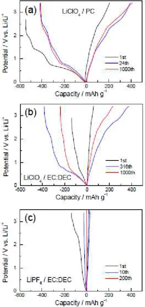
We expect that the oxygen used for the formation of RuO2 is derived from the decomposition
of the electrolyte. However, it is not clear whether it comes from the solvent of PC (C4H6O3) or the
electrolyte of lithium perchlorate (LiClO4). Firstly, we thus examined the case where EC-DEC was
used to dissolve the lithium perchlorate instead of PC. Figure 5(a) and 5(b) depict the charge-discharge curves of the Ru film electrode in the solutions of PC and EC-DEC containing LiClO4, respectively. The charge-discharge behaviors of the two solutions were similar, confirming
no significant influence from the solvents. Next, we replaced the perchlorate with LiPF6 and retained
EC-DEC as the solvent. Figure 5(c) presents the charge-discharge curves of the Ru film electrode in the solutions of EC-DEC containing LiPF6. There was virtually no trace of an electrode reaction in
the case of LiPF6. Therefore, it was clear that the oxygen to form the RuO2 is derived from the
superior cycle stability of Ru would be used with Si, we attempted to design a composite material combining Ru and Si.
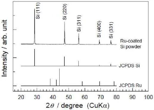
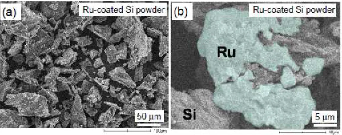
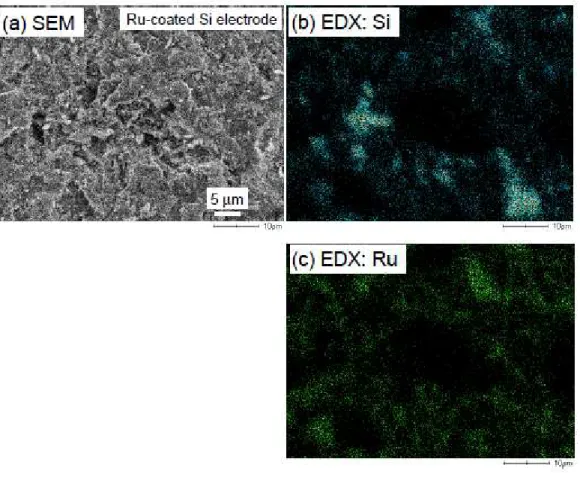
Figure 6 represents XRD pattern of Ru-coated Si powder prepared by the ELD method. All diffraction peaks of the powder can be indexed as cubic Si with the diamond structure (JCPDS No.27-1402). No diffraction peak of Ru was observed. The reason is possibly that amorphous Ru was deposited on the Si, or that thickness of Ru layer was very thin because the composition ratio of Ru:Si is 6:94 wt%. Figure 7(a) displays a SEM image of Ru-coated Si powder prepared by ELD method. The morphology of jagged edges was observed. The particle size of the Ru-coated Si powder mainly ranges from 1 to 70 µm. Figure 7(b) shows a SEM image of the Ru-coated Si powder taken at higher magnification. From the result of EDX, Ru region was indicated by green color in this figure. It is recognized that the Ru was deposited onto the surface of Si particle, and that the Si particle was partially covered with Ru. Figure 8(a) presents a SEM image of the thick film electrode consisted of Ru-coated Si on the Cu substrate prepared by the gas-deposition. Aggregated particles were found on the surface. Figure 8(b) and 8(c) show EDX results of element mapping for Si and Ru, respectively. Both elements of Ru and Si were uniformly distributed on the surface.
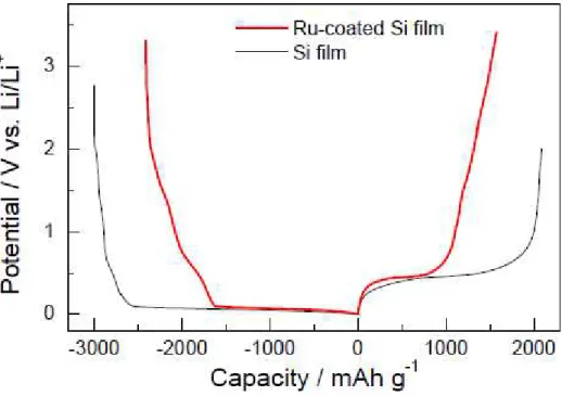
Figure 9 shows the charge-discharge (Li insertion-extraction) curves of thick film electrodes of Ru-coated Si and pristine Si at the first cycle. In the charge and discharge processes, the Si film electrode generally undergoes the following electrochemical reaction:
Si + 4.4Li+ + 4.4e- ⇄ Li
4.4Si (3)
In the Li-Si alloy system, different potential plateaus depending on different phases such as Li12Si7,
Li7Si3, Li13Si4 and Li21Si5 have been previously reported [17]. In this study, only one plateau
appeared at the potentials of about 0.1 and 0.4 V vs. Li/Li+ in the charge and discharge profiles, respectively, which is presumably due to the kinetic effect of the measurement [18]. The potential difference between the charge and discharge plateaus is attributed to a polarization of the cell. In the case of the Ru-coated Si electrode, the plateaus appeared at the same potentials. This means that Si in
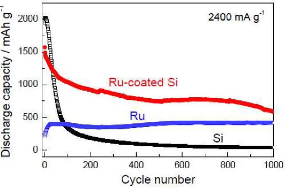
the electrode mainly contributes to the Li-storage. Figure 10 compares the cycle life performance of the thick film electrodes of Si, and Ru, and Ru-coated Si. The pristine Si electrode exhibits a rapid decay of the discharge capacity until the 100th cycle. On the other hand, the Ru-coated Si electrode shows very gentle decay. The discharge capacity at 500th cycle was 800 mA h g-1, which is twice as high as the capacity in the case of carbon-based electrodes. Their characteristics make them suitable for application as electrodes in embedded batteries for next-generation electric cars.
We also considered the reason for the improved cycle life performance. The Li insertion in Si results in the formation of Li-Si alloy (Li4.4Si). It has been reported that the volume per Si atom for
Li4.4Si is approximately four times larger than that of the parent Si atom, i.e., a 400% volume
expansion of the Si lattice takes place [9]. The violent volumetric change generates a compressive stress, which induces the breakup of the electrode and the electrical isolation of the active material. Figure 11 shows the dependence of the coulombic efficiency on the cycle number for the Ru-coated Si and Si electrodes. A significant decrease of the coulombic efficiency was observed for the Si electrode from 5th cycle to 25th cycle. This indicates that the active materials break up and are electrically isolated by volume expansion and shrinkage during the alloying and de-alloying processes, and that the irreversible capacity is increased with the cycle number. On the other hand, there was no remarkable decrease of the coulombic efficiency for the Ru-coated Si electrode. We consider that the break up and the electrical isolation were effectively suppressed because the Ru-coating acts as a buffer material to relax the stress and limits the breakup of the Si particles.
4. Summary
In this study, we obtained the following information with respect to the anode characteristics
of rechargeable Li batteries comprising the thick film electrodes prepared with the gas-deposition method by using Ru and Ru-coated Si as the source materials. The Ru electrode exhibited superior cycle stability, where the discharge capacity higher than that of carbon-based electrodes is
maintained over 1000 cycles. This electrode reaction was shown to be based on the redox reaction of RuO2 which was formed on the surface of Ru. We showed that it is possible to prepare an electrode
characterized by both high capacity and high cycleability by coating the Si with Ru. We infer that the reason for the improvement in the cycleability results from the fact that the coated Ru reduces the stress generated by the immense volumetric changes occurring in the Si particles.
Acknowledgments
This work was partially supported from the Li-EAD program of the New Energy and Industrial Technology Development Organization (NEDO) of Japan. The authors greatly thank Sumitomo Metal Mining Co., Ltd. for a helpful assistance in the cross-sectional SEM observations and EDX analysis.
References
[1] P. Balaya, H. Li, L. Kienle, and J. Maier, Adv. Funct. Mater., 130 (2003) 621.
[2] Y. F. Zhukovskii, P. Balaya, E. A. Kotomin, and J. Maier, Phys. Rev. Lett., 96 (2006) 058302.
[3] O. Delmer, P. Balaya, L. Kienle, and J. Maier, Adv. Mater., 20 (2008) 501.
[4] E. Bekaert, P. Balaya, S. Murugavel, J. Maier, and M. Ménétrier, Chem. Mater., 21 (2009) 856.
[5] P. Poizot, S. Laruelle, S. Grugeon, L. Dupont, and J.-M. Tarascon, Nature, 407 (2000) 496.
[6] P. Poizot, S. Laruelle, S. Grugeon, and J.-M. Tarascon, J. Electrochem. Soc., 149 (2002) A1212.
[7] M. Malini, U. Uma, T. Sheela, M. Ganesan, and N. G. Renganathan, Ionics, 15 (2009) 301.
[8] J. O. Besenhard. J. Yang, and M. Winter, J. Power Sources, 68 (1997) 87.
[9] U. Kasavajjula, C. S. Wang, and A. J. Appleby, J. Power Sources, 163 (2007) 1003.
[10] N. Ding, J. Xu, Y. Yao, G. Wegner, I. Lieberwirth, and C. Chena, J. Power Sources, 192 (2009) 644.
[11] M. Ichiki, J. Akedo, A. Schroth , R. Maeda, and Y. Ishikawa, Jpn. J. Appl. Phys., 36 (1997) 5815.
[12] S. Sakai, H. Tanimoto, K. Otsuka, T. Yamada, Y. Koda, E. Kita, and H. Mizubayashi, Scripta
Materialia, 45 (2001) 1313.
[13] H. Sakaguchi, T. Toda, Y. Nagao, and T. Esaka, Electrochem. Solid-State Lett., 10 (2007) J146.
[15] T. Iida, T. Hirono, N Shibamura, and H. Sakaguchi, Electrochemistry, 76 (2008) 644.
[16] H. Sakaguchi, T. Iida, M. Itoh, N Shibamura, and T. Hirono, IOP Conf. Series: Mater. Sci.
Eng., 1 (2009) 012030.
[17] W. J. Weydanz, M. W.-Mehrens, R. A. Huggins, J. Power Sources, 81-82 (1999) 237.
Fig. 1. Dependence of discharge capacity on cycle numbers for RuO2 thick film electrode prepared
by gas-deposition. The charge-discharge measurements were carried out in the electrolyte solution of PC containing LiClO4.
Fig. 3. Cross-sectional SEM images for the Ru film electrode (a) before the charge-discharge cycle and (b) after 1000 cycles.
Fig. 4. Cross-sectional SEM images of the Ru film electrodes (a1) before the charge-discharge and
(b1) after 1000 cycles. The elemental mapping results before the charge-discharge detecting (a2) Ru,
(a3) oxygen, and (a4) carbon. The elemental mapping results after the 1000 cycles detecting (b2) Ru,
Fig. 5. Charge-discharge curves (Li insertion-extraction) of the Ru film electrode in the solutions of (a) PC and (b) EC-DEC containing LiClO4, respectively. The figure (c) depicts the
Fig. 7. (a) SEM image of Ru-coated Si powder prepared by ELD method. (b) SEM image of the Ru-coated Si powder taken at higher magnification with a result of elemental mapping for Ru.
Fig. 8. (a) SEM image of the thick film electrode consisted of Ru-coated Si on the Cu substrate prepared by the gas-deposition. EDX results of element mapping for (b) Si and (c) Ru.
Fig. 9. Charge-discharge (Li insertion-extraction) curves of thick film electrodes of Ru-coated Si and pristine Si at the first cycle.
Fig. 11. Dependence of the coulombic efficiency on the cycle number for the Ru-coated Si and Si electrodes.
Figure captions
Fig. 1. Dependence of discharge capacity on cycle numbers for RuO2 thick film electrode prepared
by gas-deposition. The charge-discharge measurements were carried out in the electrolyte solution of PC containing LiClO4.
Fig. 2. Cycle life performances of Ru and Sn film electrodes prepared by the gas-deposition.
Fig. 3. Cross-sectional SEM images for the Ru film electrode (a) before the charge-discharge cycle and (b) after 1000 cycles.
Fig. 4. Cross-sectional SEM images of the Ru film electrodes (a1) before the charge-discharge and
(b1) after 1000 cycles. The elemental mapping results before the charge-discharge detecting (a2) Ru,
(a3) oxygen, and (a4) carbon. The elemental mapping results after the 1000 cycles detecting (b2) Ru,
(b3) oxygen, and (b4) carbon.
Fig. 5. Charge-discharge curves (Li insertion-extraction) of the Ru film electrode in the solutions of (a) PC and (b) EC-DEC containing LiClO4, respectively. The figure (c) depicts the
charge-discharge curves of the Ru film electrode in the solutions of EC-DEC containing LiPF6.
Fig. 7. (a) SEM image of Ru-coated Si powder prepared by ELD method. (b) SEM image of the Ru-coated Si powder taken at higher magnification with a result of elemental mapping for Ru.
Fig. 8. (a) SEM image of the thick film electrode consisted of Ru-coated Si on the Cu substrate prepared by the gas-deposition. EDX results of element mapping for (b) Si and (c) Ru.
Fig. 9. Charge-discharge (Li insertion-extraction) curves of thick film electrodes of Ru-coated Si and pristine Si at the first cycle.
Fig. 10. Cycle life performance of the thick film electrodes of Si, Ru, and Ru-coated Si.
Fig. 11. Dependence of the coulombic efficiency on the cycle number for the Ru-coated Si and Si electrodes.