THE THESIS OF DOCTOR OF PHILOSOPHY
Study on a Tele-operative Catheter
System for Endovascular
Neurosurgery
Xu Ma
Graduate School of Engineering
Kagawa University
Abstract I
Ph.D. thesis of Dr. Xu Ma
Abstract
The incidence of cardiovascular and cerebrovascular diseases has been increasing with the quickening pace of modern life. These diseases are a major cause of death, about 1.7 million people annually worldwide or accounting for 29.2% of all mortality based on a World Health Organization survey. Intracavity intervention is expected to become increasingly popular in medical practice, both for diagnosis and treatment, because of the small incision, short recovery time, and reduced burden on patients. During the past years, significant research effects have been done in the development of technology for minimally invasive surgery (MIS), such as laparoscopy, has grown as a very suitable domain for robotic system. A lot of diagnosis and medical surgery with an endoscope or a catheter are performed for minimum invasive surgery recently. There are a lot of advantages as earliness etc. However, it requires a lot of skills for the operation so that this may do the operation in the inside of the body that cannot be watched directly. In order to solve these problems, two kinds of robotic catheter systems with force feedback and visual feedback have been developed in this thesis, in addition, the force sensors system and the feedback system have been developed to detect the contact force information so as to let neurosurgeon know the contact information during vascular interventional surgery. Based on this information, the neurosurgeon can avoid danger during the operation.
II Study on a Tele-operative Catheter System for Endovascular Neurosurgery
In this thesis, the two kinds of robotic catheter systems with the structure of master-slave have been developed. Firstly, we developed a novel kind of robot-assisted catheter system and this system can realize the force feedback and visual feedback to enhance the safety during the operation. The robot-assisted catheter system is equipped with the structure of master-slave. In the master side, there consists of the master control system and master manipulator which can accord with the operating habit of the neurosurgeon, it is the first one can simulate the operating skill and extract the operating skill from experienced neurosurgeon in the world. The neurosurgeon operates the right handle of the master manipulator meanwhile the operating instructions are transmitted to the slave manipulator. Based on the operating instructions transmitted from master side, the slave manipulator drives the catheter to insert and rotate inside the blood vessel of patient. A loadcell is linked to the catheter supporting frame to measure the friction force reflected on the catheter and the force measured by loadcell can be transmitted to the master manipulator and generate a haptic feedback to the neurosurgeon. We used an optical fiber force sensor to measure the contact force between catheter tip and blood vessel. The force information measured by the optical fiber force sensor will be transmitted to the master side and display to the neurosurgeon by using the user interface. In addition, we used an IP camera to monitor the situation of the operation and the monitoring image will be transmitted to the neurosurgeon. So the feedback system including
Abstract III
Ph.D. thesis of Dr. Xu Ma
force feedback and visual feedback is realized and it is used to enhance the safety during vascular interventional surgery. Next, this thesis presents the evaluation performance of robot-assisted catheter system, including master manipulator and slave manipulator. In order to operate inside the blood vessel, PID fuzzy controller were developed to compensate for the catheter performance limitations and evaluated with “vitro” experiments. Through the addition of compensation terms, the system is able to achieve position tracking with less than 1 mm RMS error and rotation tracking with 3o RMS error.
Unlike the conventional bedside technique, which requires surgeons to manipulate a catheter using their hands, employment of these remote manipulating systems removes the catheter from the surgeons’ hands, thus removing his/her dexterous and intuitive skills from the procedure. Furthermore, the technological complexities of these systems may require long training times to ensure that the surgeons are skilled in their use. Therefore, it should be beneficial if a catheter manipulating system incorporated the dexterous skill set of an experienced surgeon during the procedures.
Secondly, a new prototype robotic catheter manipulating system has been designed and constructed based on the requirements for the endovascular surgery. Compared with system mentioned above, this system features a master controller called surgeon console, using two motion-sensing devices via control unit DSP to communicate the position and rotation information with slave side. Also, we designed the
IV Study on a Tele-operative Catheter System for Endovascular Neurosurgery
haptic device to provide the feeling back to surgeons. The whole system was evaluated in aspect of dynamic and static performance of the axial and radial motions. The results of synchronization experiments had to evaluate the accuracy and precision of sensed and replicated motions. Finally, Tele-operation had been done by EVE simulator to provide the performance under the similar situations.
A number of improvements can be made to the robotic catheter system in the areas of mechanical design and control. The system can also be applied to new medical applications, including neurosurgery and peripheral vascular disease. In the future, the performance of the measurement mechanism of friction force and the haptic device will be discussed. Furthermore, the current limitations of the robotic catheter control system are accurate position control of the catheter tip and the 3D image servoing system. The model-based feedforward position control of the catheter tip is not able to adapt to changes in the environment or catheter configuration. This shortcoming could be overcome with accurate tip position measurements. Finally, utilizing this system to perform a range of interventional surgery in vivo is required to the clinical practice.
Contents V Ph.D. thesis of Dr. Xu Ma
Contents
Abstract ... I Contents ... V List of Tables ... IX List of Figures ... XI Acknowledgements ... XVII Declaration ... XIX Chapter 1 Introduction ... 1 1.1 Preface ... 1 1.2 Background ... 2 1.3 Literature review ... 5 1.4 Contributions ... 11 1.5 Thesis structure ... 13Chapter 2 The robot-assisted catheter system ... 15
2.1 The system structure ... 17
2.1.1 The master system ... 17
2.1.2 The slave system ... 19
2.2 Communication system ... 22
2.3 The design of control system ... 24
2.3.1 Modeling of the inserting motion ... 24
VI Study on a Tele-operative Catheter System for Endovascular Neurosurgery
2.3.3 Modeling of the rotating motion ... 28
2.3.4 Numerical simulation for the rotating motion ... 29
2.4 Realization of the control system ... 31
2.5 The design of the feedback system ... 36
2.5.1 Introduction ... 36
2.5.2 Realization of the force feedback ... 37
2.5.3 Realization of the visual feedback ... 39
2.6 The performance evaluation ... 41
2.6.1 Introduction ... 41
2.6.2 Evaluation of the master manipulator ... 41
2.6.3 Evaluation of the slave manipulator ... 44
2.6.4 Evaluation of the tracking performance ... 45
2.6.5 Evaluated results ... 46
2.7 Summary ... 52
Chapter 3 Experiment by PID fuzzy control ... 55
3.1 Introduction ... 55
3.2 Fuzzy Control ... 55
3.2.1 Input variables and normalization ... 57
3.2.2 Fuzzification and membership functions ... 58
3.2.3 Rule base ... 59
3.2.4 Inference engine ... 60
3.2.5 Defuzzification ... 61
Contents VII
Ph.D. thesis of Dr. Xu Ma
3.2.7 PID fuzzy control ... 63
3.3 Modeling of the RCMS dynamics ... 65
3.3.1 Dynamic model of the axial motion ... 65
3.3.2 Dynamic model of the rotational motion ... 67
3.3.3 Fuzzy PID controller design of the RCMS ... 69
3.4 Experiments ... 73
3.4.1 Experimental setup ... 73
3.4.2 Experimental results ... 75
3.5 Summary ... 80
Chapter 4 The novel robotic catheter manipulating system... 83
4.1 The system design ... 86
4.2 The catheter manipulator ... 87
4.3 The surgeon console ... 91
4.4 Control of the system ... 96
4.5 Summary ... 97
Chapter 5 The performance evaluation... 99
5.1 Evaluation method ... 99
5.1.1 Evaluation of the surgeon console ... 99
5.1.2 Evaluation of the catheter manipulator ... 102
5.1.3 Evaluation of the synchronization performance ... 103
5.2 Experimental results ... 103
5.2.1 Evaluation of surgeon console and catheter manipulator .... 103
VIII Study on a Tele-operative Catheter System for Endovascular Neurosurgery
5.3 Summary ... 111
Chapter 6 Insertion experiment in “Vitro” ... 113
6.1 Introduction ... 113
6.2 Experimental environment ... 114
6.3 Experiment and results ... 115
6.4 Summary ... 119
Chapter 7 Conclusions and future work ... 121
7.1 Conclusions ... 121
7.1.1 System Design ... 122
7.1.2 User Interface ... 124
7.1.3 Real-Time Position Sensing ... 124
7.1.4 Haptic Feedback ... 125 7.1.5 Clinical Applications ... 126 7.2 Future work ... 126 7.2.1 Mechanical Design ... 126 7.2.2 Control ... 127 7.2.3 New Applications ... 128 References ... 129 Publication List ... 141 Appendix I ... 145 Appendix II ... 173 Biographic Sketch ... 216
List of tables IX
Ph.D. thesis of Dr. Xu Ma
List of Tables
Table 2- 1 Precision evaluation result of master manipulator ... 48 Table 2- 2 Precision evaluation result of slave manipulator ... 48 Table 5- 3 Evaluation of the precision and accuracy ... 105
List of Figures XI
Ph.D. thesis of Dr. Xu Ma
List of Figures
Figure1- 1 Cerebral angiogram [Padalino13] ... 4
Figure1- 2 Stent assisted aneurysm coil embolization [Spiotta12] ... 5
Figure1- 3 ANGIO Mentor endovascular surgical training simulator .... 7
Figure1- 4 Sensei Robotic Catheter System ... 8
Figure1- 5 Amigo remote catheter system ... 9
Figure1- 6 Catheter Guidance Control and Imaging’ (CGCI) system .... 9
Figure1- 7 Stereotaxis Niobe II ... 10
Figure1- 8 The structure of the thesis ... 14
Figure 2- 1 The conceptual diagram of robot-assisted catheter system 16 Figure 2- 2 The flow chart of the control instructions ... 17
Figure 2- 3 The developed master-slave robot-assisted catheter system ... 18
Figure 2- 4 The master system ... 19
Figure 2- 5 The slave system ... 21
Figure 2- 6 The moving mode of catheter ... 21
Figure 2- 7 The communication system based on RS 422 ... 23
Figure 2- 8 The communication system based on internet ... 23
Figure 2- 9 The control of the inserting motion ... 26
Figure 2- 10 The developed PID controller (Insertion) ... 27
XII Study on a Tele-operative Catheter System for Endovascular Neurosurgery
Figure 2- 12 System response with step input signal ... 28
Figure 2- 13 The control of the rotating motion ... 30
Figure 2- 14 The developed PID controller (Rotation) ... 30
Figure 2- 15 System response with step input signal ... 31
Figure 2- 16 System response with sinusoid input signal ... 31
Figure 2- 17 The control system (both master side and slave side) ... 32
Figure 2- 18 The control system of catheter graspers ... 32
Figure 2- 19 The control circuit of the master system ... 33
Figure 2- 20 The control circuit of the slave system ... 34
Figure 2- 21 The control circuit of catheter graspers ... 35
Figure 2- 22 Measuring contact force and friction ... 37
Figure 2- 23 The feedback force measuring mechanism ... 38
Figure 2- 24 The transmission of force feedback ... 39
Figure 2- 25 The IP camera for monitoring situation of operation (VIVOTEK FD8133V) ... 40
Figure 2- 26 The user interface for monitoring contact force ... 40
Figure 2- 27 The transmission of visual feedback signal ... 41
Figure 2- 28 The evaluating system of the master manipulator ... 43
Figure 2- 29 The evaluated method for axial precision ... 43
Figure 2- 30 The evaluated method for radial precision ... 44
Figure 2- 31 The evaluating system of the slave manipulator ... 45
Figure 2- 32 The evaluating system of the tracking performance ... 46
Figure 2- 33 The axial motion tracking curve ... 49
List of Figures XIII
Ph.D. thesis of Dr. Xu Ma
Figure 2- 35 The axial notion tracking statistic ... 51
Figure 2- 36 The radial motion tracking statistic ... 51
Figure 3- 1 General structure of fuzzy control ... 57
Figure 3- 2 Conventional FC diagram ... 63
Figure 3- 3 Fuzzy PID control diagram ... 64
Figure 3- 4 Diagram of axial dynamic model ... 65
Figure 3- 5 Diagram of rotational dynamic model ... 65
Figure 3- 6 Principle Diagram of fuzzy PID Control ... 70
Figure 3- 7 Membership function for thee k( ) andce k( ) ... 71
Figure 3- 8 Membership function ... 72
Figure 3- 9 Diagram of the experimental setup for the fuzzy PID controller ... 75
Figure 3- 10 Axial tracking curve with PID ... 77
Figure 3- 11 Input force signal ... 77
Figure 3- 12 Axial tracking curve with fuzzy PID ... 78
Figure 3- 13 Input force signal ... 78
Figure 3- 14 Rotation tracking curve with PID ... 79
Figure 3- 15 Rotation tracking curve with fuzzy PID ... 80
Figure 4- 1 The robotic catheter manipulating system ... 85
Figure 4- 2 The communication sketch map ... 86
XIV Study on a Tele-operative Catheter System for Endovascular Neurosurgery
Figure 4- 4 The insertion motion ... 90
Figure 4- 5 The force measurement mechanism ... 91
Figure 4- 6 The structure of the surgeon console ... 93
Figure 4- 7 The schematic diagram of surgeon console ... 93
Figure 4- 8 Haptic device in the surgeon console ... 95
Figure 4- 9 Schematic diagram of haptic device ... 95
Figure 4- 10 Schematic diagram of the flex sensor ... 96
Figure 5- 1 Experimental setup of performance evaluation of axial motion ... 100
Figure 5- 2 Experimental setup of performance evaluation of radial motion ... 100
Figure 5- 3 Dynamic performance of axial motion at 0.1Hz ... 106
Figure 5- 4 Dynamic characterization of axial motion ... 106
Figure 5- 5 Static performance of axial motion at 0.7mm/s ... 107
Figure 5- 6 Static characterization of axial motion ... 107
Figure 5- 7 Static performance of radial motion at 270 deg/s ... 108
Figure 5- 8 Static characterization of radial motion ... 108
Figure 5- 9 The tracking curve of axial motion ... 109
Figure 5- 10 The inserting velocity in both sides... 109
Figure 5- 11 The tracking curve of radial motion ... 110
Figure 5- 12 The rotational velocity in both sides ... 110
List of Figures XV
Ph.D. thesis of Dr. Xu Ma
Figure 6- 2 Experimental system ... 117 Figure 6- 3 Tracking trajectory of the axial direction ... 118 Figure 6- 4 Contact force signal described as pressure ... 118
Acknowledgements XVII
Ph.D. thesis of Dr. Xu Ma
Acknowledgements
The author wishes to express his great gratitude to his supervisor Professor Shuxiang Guo for his invaluable guidance, support and friendly encouragement throughout my Ph.D. course and for providing me with first class resources.
The author would like to thank Prof. Hideyuki Hirata and Prof. Keisuke Suzuki. Thanks them for their valuable advices and suggestion on my research. Without their help, I can hardly finish this thesis.
Also the author would like to acknowledge the efforts of his laboratory members, especially Dr. Nan Xiao whose time and expertise were greatly appreciated.
This research was supported by Kagawa University Specially Promoted Research fund 2009-2011.
Finally, the author gives special appreciation to his parents for their love, patience and support.
Declaration XIX
Ph.D. thesis of Dr. Xu Ma
Declaration
I hereby declare that this submission is my own work and that to the best of my knowledge and belief. It contains no material previously published or written by another person nor material which to a substantial extent has been accepted for the award of any other degree or diploma of the university or other institute of higher learning, except where due acknowledgment has been made in the text.
Chapter 1 Introduction 1
Ph.D. thesis of Dr. Xu Ma
Chapter 1
Introduction
1.1 Preface
In this thesis, two kinds of robotic catheter systems with force feedback and visual feedback are proposed and developed for endovascular neurosurgery: the catheter operating system and the robot-assisted catheter system. Both two kinds of catheter systems can avoid danger effectively during operation based on the feedback system included force feedback and visual feedback. In addition, we developed a force sensors system and two kinds of user interfaces which is used to monitor the contact force measured by force sensors. The controller of the robot-assisted catheter system can simulate the neurosurgeon’s operating skill to operate the catheter, furthermore, it can extract the operating skill of experienced neurosurgeon to train unskilled neurosurgeon or novice. We did the performance evaluation and carried out the simulation experiment in vitro, the evaluated results and experimental results indicated that the developed two kinds of robotic catheter system work well, both them can avoid danger effectively during vascular interventional surgery.
2 Study on a Tele-operative Catheter System for Endovascular Neurosurgery
1.2 Background
With the quickening pace of modern life, the brain diseases of people are increasing, such as cerebral aneurysm and infarction and so on. The traditional surgery spends patients a lot of operation time and has long recovery time, the burden on patients is heavy. Minimally invasive surgery (MIS) has grown as a very suitable domain by using robot-assisted system. A lot of diagnosis and medical surgery with an endoscope or a catheter are performed for minimally invasive surgery recently. The diagram of the embolization operation is shown in Figure 1-1, and the Figure 1-2 shows the coil embolization surgery, it is difficult for novice to insert the catheter from femoral to the position of embolization in the blood vessel of patient’s brain. There are a lot of advantages as earliness etc. However, it requires a lot of skills for the operation so that this may do the operation in the inside of the body that cannot be watched directly. Such surgery presents many challenges:
1) Doctors must be very well trained and possess the skills and experience to insert catheters. Intravascular neurosurgery is much more difficult than traditional surgery and there are few skilled doctors who can perform this type of operation. To keep pace with the growing number of patients, a mechanism is required to allow the training of sufficient numbers of doctors.
Declaration 3
Ph.D. thesis of Dr. Xu Ma
using the X-ray camera. Although they wear protective suits, it is very difficult to shield the doctor’s hands and face from the effects of the X-ray radiation, which may result in radiation-related illness after long periods of exposure.
3) In intravascular neurosurgery, catheters are inserted into the patient’s blood vessels, which in the brain are very sensitive. When operating in this area, extreme care is required to avoid damaging the fragile vessels. An experienced neurosurgeon can achieve an accuracy of about 2 mm. However, as the contact force between the blood vessel and the catheter cannot be judged accurately by the doctor, so how to measure the contact force and feedback to the surgeon become significant.
4) There is not a kind of robotic catheter system can imitate surgeon’s operating skill to insert and rotate catheter. Therefore, a master-slave robot-assisted catheter system is required for such cases so that the operation can be proceeded.
Based on aforementioned background, in this paper, we proposed and developed two kinds of robotic catheter systems with force feedback and visual feedback, the first robotic catheter system used the Phantom Omni as the controller to control the catheter operating mechanism on the slave side, however, it cannot accord with the operating habit of the neurosurgeon, the second robot-assisted catheter system was proposed and developed based on the problems existing in the first robotic
4 Study on a Tele-operative Catheter System for Endovascular Neurosurgery
catheter system, it is also with a structure of master-slave, it can transmit the neurosurgeon’s skill at inserting and rotating a catheter. It avoids danger during vascular interventional surgery (VIS) by making use of force feedback and visual feedback.
(a) A basilar apex aneurysm pretreatment. (b) Lateral view of the Enterprise stent deployed in the aneurysm dome. (c) A small basilar apex aneurysm recurrence before redo treatment. (d) Redo coil embolization of recurrent aneurysm. (e) After redo coil embolization showing no further recurrence.
Declaration 5
Ph.D. thesis of Dr. Xu Ma
Figure1- 2 Stent assisted aneurysm coil embolization [Spiotta12]
1.3 Literature review
There are some relative products and researches on catheter system in the world. Recently, telesurgery performed using a microscopic micromanipulator system called the “NeuRobot” was reported in Neurosurgery. In this case report, the authors proved that the use of the NeuRobot was feasible using a private network [Goto09]. Many technological advances have been reported, including the following: a new prototype of a microcatheter with an active guidewire that has two bending degrees of freedom and is made using ionic conducting
a) b)
c) d)
6 Study on a Tele-operative Catheter System for Endovascular Neurosurgery
polymer film (ICPF) with a shape memory alloy (SMA) actuator fixed at its end to act as a servo actuator [Fukuda94-96]; a master-slave catheterization system for positioning a steerable catheter [Fu11]; a new catheter driving method using a linear step mechanism for intravascular neurosurgery [Arai02]; force sensors based on a catheter operating system [Guo07-11]; research on an tele-operating system for medical application [Marcelli08]; state-of-the-art in force and tactile sensing for minimally invasive surgery [Puangmali08]; a feasibility study measuring the tip and side forces of a novel catheter prototype [ Polygerinos09] and contact and friction between the catheter and blood vessel [Takashima07]; [Wang11] reported on the actuation and localization of an active capsule endoscope and [Marcelli08] reported a novel telerobotic system to navigate standard electrophysiology catheters remotely. Further, [Preusche02] reported the concept of teleoperation in minimally invasive surgery. In addition, a robot mechanism for the remote steering and positioning of interventional devices has been fabricated [Srima/thveeravalli10], remote-controlled vascular interventional surgery robot was reported [Wang10] and so on.
The ANGIO Mentor provides fully simulated, hands-on practice of interventional endovascular procedures [OKB Medical Ltd.]. It has been designed for interventional cardiologists, interventional radiologists and vascular surgeons and trainees, allowing the performance of full procedures as well as the training of basic skills.
Declaration 7
Ph.D. thesis of Dr. Xu Ma
Angio Mentor which is shown in Figure 1-3 allows trainees to perform a diagnostic angiogram by inserting a catheter into an artery under fluoroscopic guidance, along with subsequent injection of contrast agent.
Figure1- 3 ANGIO Mentor endovascular surgical training simulator (Simbionix Corporation in Israel, 2008)
One of the most popular product is a robotic catheter placement system called Sensei Robotic Catheter System [Kanagaratnam08] offered by Hansen Medical shown in Figure 1-4. The Sensei provides the physician with more stability and more force in catheter placement with the Artisan sheath compared to manual techniques, allowing for
8 Study on a Tele-operative Catheter System for Endovascular Neurosurgery
more precise manipulation with less radiation exposure to the doctor, commensurate with higher procedural complications to the patient. Because of the sheath’s multiple degrees of freedom, force detection at the distal tip is very hard.
Figure1- 4 Sensei Robotic Catheter System
Catheter Robotics Inc. has developed a remote catheter system called Amigo shown in Figure 1-5. This system has a robotic sheath to steer catheters which is controlled at a nearby work station, in a manner similar to the Sensei system. The first in human use of this system was
Declaration 9
Ph.D. thesis of Dr. Xu Ma
in April 2010 in Leicester UK, where it was used to ablate atrial flutter.
Figure1- 5 Amigo remote catheter system
10 Study on a Tele-operative Catheter System for Endovascular Neurosurgery
Magnatecs Inc. has produce their ‘Catheter Guidance Control and Imaging’ (CGCI) system as shown in Figure 1-6. This has 4 large magnets placed around the table, with customized catheters containing magnets in the tip. The catheter is again moved by the magnetic fields and is controlled at a nearby work station.
The Stereotaxis Inc. developed a magnetic navigation system: the Stereotaxis Niobe II [Stargen Inc.] shows in Figure 1-7. The system facilitates precise vector based navigation of magnetically-enabled guide wires for percutaneous coronary intervention (PCI) by using two permanent magnets located on opposite sides of the patient table to produce a controllable magnetic field.
Declaration 11
Ph.D. thesis of Dr. Xu Ma
Although these products have been developed and marketed, most concern is still the safety of the system. Force information on the catheter during the operation is very important to insure the safety of the surgery. However, detection of the force on catheters is very hard to solve in these systems. A potential problem with a remote catheter control system is the lack of mechanical feedback that one would receive from manually controlling a catheter [Kanagaratnam08]. To solve the problems, we proposed two kinds of novel catheter systems with force feedback and visual feedback in this thesis.
1.4 Contributions
In this thesis, two kinds of robotic catheter operating systems with force feedback and visual feedback were proposed and developed, and the force sensors system were developed to measure the contact force between catheter and blood vessel. In addition, two kinds of user interfaces for monitoring the contact forces were developed. The mainly contributions of two kinds of robotic catheter systems are as following:
(1) The first robotic catheter system: A robot-assisted catheter system with force feedback and visual feedback was developed. We also proposed a mechanism which can be used to measure the operating force on the catheter, and the force information can be transmitted to
12 Study on a Tele-operative Catheter System for Endovascular Neurosurgery
the master manipulator and generate a haptic feedback to the neurosurgery, via the haptic feedback, the neurosurgeon can decide whether inserting the catheter or not. We carried out the performance evaluation for the robot-assisted catheter system, and also, we did the tele-operation by PID fuzzy control method. The evaluated results and experimental results imply that the developed robot-assisted catheter system with force feedback and visual feedback work very well, it is suitable for supporting neurosurgeons to the vascular interventional surgery. In addition, the robot-assisted catheter system can be used to train unskilled or inexperience neurosurgeon.
(2) The second robot-assisted catheter system: a new prototype robotic catheter manipulating system has been designed and constructed based on the requirements for the endovascular surgery. Compared with system mentioned above, this system features a master controller called surgeon console, using two motion-sensing devices via control unit DSP to communicate the position and rotation information with slave side. Also, we designed the haptic device to provide the feeling back to surgeons. The whole system was evaluated in aspect of dynamic and static performance of the axial and radial motions. The results of synchronization experiments had to evaluate the accuracy and precision of sensed and replicated motions. Finally, Tele-operation had been done by EVE simulator to provide the performance under the similar situations.
Declaration 13
Ph.D. thesis of Dr. Xu Ma
(3) The user interface for monitoring the contact force between catheter and blood vessel were developed. The force monitoring system and danger avoiding system were applied in the robotic catheter system. They can monitor the contact force information in real time. If the force on the catheter goes beyond the safety range, the doctor will get warning information from both monitors and controller. The experimental results imply that the developed user interfaces for monitoring force is effective to help neurosurgeon avoid danger during operation.
1.5 Thesis structure
Figure 1-8 shows the structure of the thesis. Chapter 1 is the introduction. It is composed of preface, background, literature review, research purposes, research approaches and thesis structure. In chapter 2, one kind of catheter operating system will be introduced. We developed mechanical system, control system and feedback system. Then we carried out the performance evaluation to confirm the validity of the robot-assisted catheter system. Chapter 3 introduces the tele-operation by PID fuzzy control method. In chapter 4, a novel robotic catheter manipulating system has been proposed. The system structure and system control realization have been introduced. In chapter 5, we do the performance evaluation of the novel robotic catheter manipulating system. In chapter 6, we carry out the catheter inserting
14 Study on a Tele-operative Catheter System for Endovascular Neurosurgery
experiment by using endovascular evaluator (EVE) model. In chapter 7, conclusions and future work are given.
Chapter 2 The robot-assisted catheter system 15
Ph.D. thesis of Dr. Xu Ma
Chapter 2
The robot-assisted catheter system
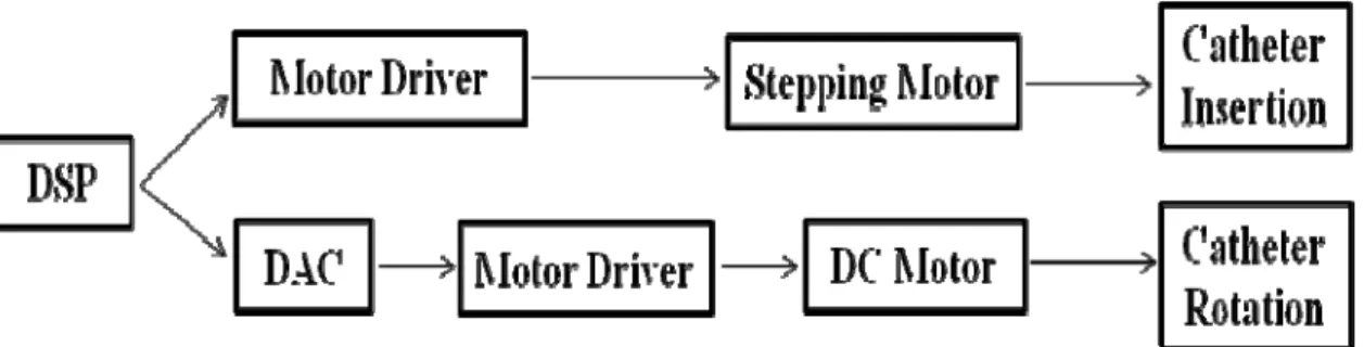
Based on the aforementioned problems in the chapter 1, we designed and developed a kind of robot-assisted catheter system for supporting neurosurgeons to do the operation of vascular interventional surgery, also, this kind of robotic catheter system can be used to train unskilled neurosurgeon to complete the operation, the conceptual diagram of the master-slave robotic catheter system is shown in Figure 2-1. On the master side, the surgeon views a monitor and operates the master manipulator. The control instructions are transmitted to the slave side. After receiving instructions, the slave manipulator inserts and rotates the catheter. The motions of the catheter on the slave side follow the motions of the catheter on the master side. Consequently, the surgeon appears to operate the catheter as though adjacent to the patient, controlling the position and velocity of the catheter. An IP camera is used to monitor the operation and provide visual feedback to surgeon. If the catheter contacts a blood vessel wall, the force is detected and transmitted to the neurosurgeon’s hand, realizing force feedback. Figure 2-2 is a flow chart of the control instructions for our robotic catheter system. The robotic system avoids danger during the operation via force and visual feedback.
16 Study on a Tele-operative Catheter System for Endovascular Neurosurgery
Both master manipulator and slave manipulator employ DSP (TI, TMS320F28335) as their control units, Communication between master manipulator and slave manipulator is realized by the TCP/IP protocol communication in tele-operation and SPI (RS 422) in local operation.
Chapter 2 The robot-assisted catheter system 17
Ph.D. thesis of Dr. Xu Ma
Figure 2- 2 The flow chart of the control instructions
2.1 The system structure
The Figure 2-3 shows the developed robot-assisted catheter system, which is with the structure of the mater-slave, both the master system and the slave system have two degree of freedoms (DOFs), the two parts keep the same moving mode at the same time, the communication between the two parts was realized based on RS 422 and internet.
2.1.1 The master system
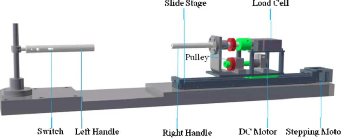
On the master side, the slide platform is fixed on the supporting frame (Figure 2-4). The master system devices, including a left handle with one switch, a right handle, step motor, load cell, and maxon DC motor, are on the slide platform. A switch placed on the left handle is used to control these two graspers in slave side, only one switch is
18 Study on a Tele-operative Catheter System for Endovascular Neurosurgery
enough because the catheter is clamped by one grasper at the same time. Operator’s action is measured by using the right handle. The handle takes the same movement motion with the slave manipulator, it has two DOFs, one is axial motion and the other one is radial motion. The handle is sustained by a bearing, and is linked to a loadcell, a pulle is fixed on the handle, a DC motor is applied to generate torque feedback, a pulley which is couple to the upper one is fixed to the axle of the motor. The step motor is used to drive the slide platform forward and backward.
Figure 2- 3 The developed master-slave robot-assisted catheter system
a)
Chapter 2 The robot-assisted catheter system 19
Ph.D. thesis of Dr. Xu Ma
The neurosurgeon moves the catheter forward and backward or rotates the right handle on the master side as though the neurosurgeon was beside the patient. The operating information from the handle is transmitted to the slave side, where the catheter clamp inserts and rotates the actual catheter as commanded from the master side. If the catheter contacts a blood vessel wall, the load cell detects it and the information is transmitted to the neurosurgeon’s hand. Force feedback is realized by the master-slave robotic catheter operating system. The neurosurgeon feels the contact, and no x-rays are required during intravascular neurosurgery.
Figure 2- 4 The master system
2.1.2 The slave system
The slave side mechanism shown in Figure 2-5 is similar to the master side, it also has two DOFs, one is axial motion along the frame, and the other one is radial motion, two graspers are placed at this part.
20 Study on a Tele-operative Catheter System for Endovascular Neurosurgery
The operator can drive the catheter to move along both axial and radial when the catheter is clamped by grasper 1. The catheter keeps its position and the catheter driven part can move smoothly when the catheter is clamped by grasper 2. The slave side consists of a catheter clamping device, two DC motors, a slide platform, step motor, maxon DC motor, load cell, torque sensor, and support frame. a slide platform is fixed on the supporting frame. The devices of the slave system are on the slide platform. The step motor is used to the drive slide platform forward and backward and the maxon DC motor is used to rotate the catheter. The two DC motors are used to control the catheter graspers. The load cell is used to measure the force between the catheter and blood vessel wall and the torque sensor and maxon DC motor are used to measure the information of catheter rotation during the operation. The measured force information is transmitted to the neurosurgeon’s hand, so that the neurosurgeon can feel the feedback information from the slave side. A switch on the left handle on the master side controls the catheter graspers. When the operator wants to insert or rotate the catheter, grasper 2 is raised and grasper 1 clamps the catheter. The catheter navigator moves forward with the catheter for insertion or rotation. The grasper 2 then clamps the catheter, grasper 1 is raised and the catheter navigator moves backward. The moving mode of catheter is shown in Figure 2-6. Repeating these actions, the actions of the slave side follow the commands of the master side. If the catheter contacts the blood vessel wall, the force information is detected and transmitted
Chapter 2 The robot-assisted catheter system 21
Ph.D. thesis of Dr. Xu Ma to the neurosurgeon’s hand.
Figure 2- 5 The slave system
Figure 2- 6 The moving mode of catheter
a) b)
22 Study on a Tele-operative Catheter System for Endovascular Neurosurgery
2.2 Communication system
We designed two kinds of communication system, one kind is based on the RS 422, the conceptual diagram of the communication system based on RS 422 is shown in Figure 2-7, two pieces of DSP is connected by serial peripheral interface (SPI), the cable which is used to connect the two pieces of DSP is about 5m, the operating data both master side and slave side are saved to the PC which is connected to the DSP on the master side with RS 232. And the other kind is based on internet, the conceptual diagram of the communication system based on internet is shown in Figure 2-8. The two PC (one is on the master side, and the other is on the slave side) are connected with TCP/IP communication, and for each side serial communication was employed. The baud rate is set to 19200. The master side sends the information of axial displacement and rotation angle of the handle to the catheter manipulator on the slave side. At the same time the slave manipulator sends force information to the master side.
Chapter 2 The robot-assisted catheter system 23
Ph.D. thesis of Dr. Xu Ma
Figure 2- 7 The communication system based on RS 422
24 Study on a Tele-operative Catheter System for Endovascular Neurosurgery
2.3 The design of control system
2.3.1 Modeling of the inserting motionIn order to keep the consistency and accuracy in inserting motion, meanwhile reducing the hysteresis in real time, we used the PID algorithm to resolve these problems. We establish a dynamic equation in inserting direction, is shown in Eq.2-1, numerical simulation experiments were carried out by Matlab.
( ) m ( )F t x t c x t( ) kx t( )
•• •
= + + (Eq.2-1) Where F t is the pull force, ( )( ) x t is the displacement of master
manipulator, x t( )
•
is the velocity of master manipulator. Definex t1( )= x t( ), x t2( ) x t( ) • = then ( ) ( ) ( ) ( ) ( ) x t AX t Bu t y t CX t • = + = (Eq.2-2) Where 1 2 ( ) ( ) ( ) x t X t x t ⎡ ⎤ = ⎢ ⎥ ⎣ ⎦, 0 1 A k c m m ⎡ ⎤ ⎢ ⎥ = ⎢− − ⎥ ⎣ ⎦ , 0 1 B m ⎡ ⎤ ⎢ ⎥ = ⎢ ⎥ ⎣ ⎦ ,C=
[
1 0]
m is the quality of master manipulator , c is the viscous damping
coefficient, k is the stiffness.
When the operator operates the right handle of master manipulator, the load cell will get the pull force from the operator and the resistance
Chapter 2 The robot-assisted catheter system 25
Ph.D. thesis of Dr. Xu Ma
force that is created by load cell part and stiffness. Based on this relationship, we can find that the whole operation is defined that the velocity of operator manipulation is as same as the step motor. To avoid the excessive overshoot, we use PID algorithm to control the output which can keep the consistence with the operation of operator. The control strategy is shown as following:
0 ( ) ( ) p ( ) i t ( ) ( ) d de t u t k e t k e t d t k dt = +
∫
+ (Eq.2-3) As on the master side, based on the input and output of the step motor, we used the same PID control strategy on the slave side to control the consistency and response of the slave mechanism during insertion.2.3.2 Numerical simulation for the inserting motion
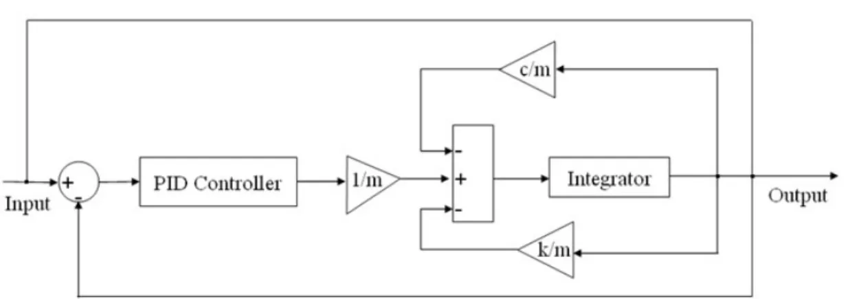
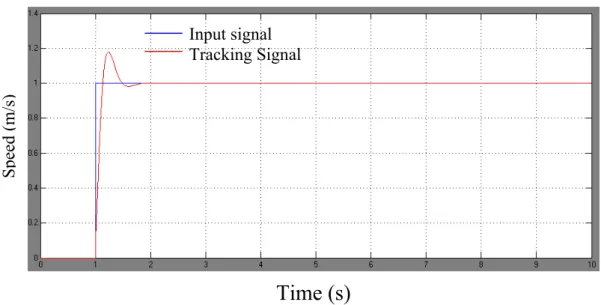
Figure 2-9 shows the control principle diagram of the inserting motion by Matlab Simulink. Figure 2-10 shows the developed PID controller for the insertion control. During the simulation of an operation, the results of the system response with sinusoid input signal and the system response with step input signal are shown in Figure 2-11
and Figure 2-12. The blue line shows the disturbing signal and the red line shows the tracking signal. From the diagram we can see that the manipulation of mechanic system can follow well with operator operations. Between 0.1s and 0.2s, the system can keep up with the
26 Study on a Tele-operative Catheter System for Endovascular Neurosurgery
actions of neurosurgeon. Despite there has a certain of overshoot, it can catch up as soon.
Parameters of the manipulation system are as following: 2 , 0.02 / ( / ), 10 /
m= kg c= N m s k = N m
Parameters of the developed PID controller are as following:
30, 400, 1
p i d
k = k = k =
Chapter 2 The robot-assisted catheter system 27
Ph.D. thesis of Dr. Xu Ma
Figure 2- 10 The developed PID controller (Insertion)
Time (s)
Figure 2- 11 System response with sinusoid input signal
Input signal Tracking signal S pee d (m/s )
28 Study on a Tele-operative Catheter System for Endovascular Neurosurgery
Time (s)
Figure 2- 12 System response with step input signal
2.3.3 Modeling of the rotating motion
An equation can be established using torque balance in rotating motion of master side, which is shown in Eq.2-4, m is the quality of manipulating system (on the movement stage of master side) ,c is the viscous damping coefficient,m=2 ,kg c=0.02 / ( / ),N m s
θ
is rotatingangle, u(t) is the variation of torque, which consists of torque of maxon motor and torque of right handle,
θ
• is the angular velocity,θ
•• is the angular acceleration,( )
m
θ
cθ
u t•• •
+ = (Eq.2-4) The equation of state was established, which is shown in Eq.4-5, define
θ
1( )tθ
( ), ( )tθ
2 tθ
( )t • = = . ( ) ( ) ( ) ( ) ( ) x t AX t Bu t y t CX t • = + = (Eq.2-5) S peed (m/s ) Input signal Tracking SignalChapter 2 The robot-assisted catheter system 29 Ph.D. thesis of Dr. Xu Ma Where, 1 2 ( ) ( ) ( ) t X t t
θ
θ
⎡ ⎤ = ⎢ ⎥ ⎣ ⎦, 0 1 0 A c m ⎡ ⎤ ⎢ ⎥ = ⎢ − ⎥ ⎣ ⎦ , 0 1 B m ⎡ ⎤ ⎢ ⎥ = ⎢ ⎥ ⎣ ⎦ , C =[
1 0]
The controlling strategy is shown in Eq.2-6,
0 ( ) ( ) p ( ) i t ( ) ( ) d de t u t k e t k e t d t k dt = +
∫
+ (Eq.2-6) Where 480,kp = ki =7,kd =28As on the master side, based on the input and output of the maxon DC motor, we used the same PID control strategy on the slave side to ensure the consistency and response of the slave mechanism for rotation.
2.3.4 Numerical simulation for the rotating motion
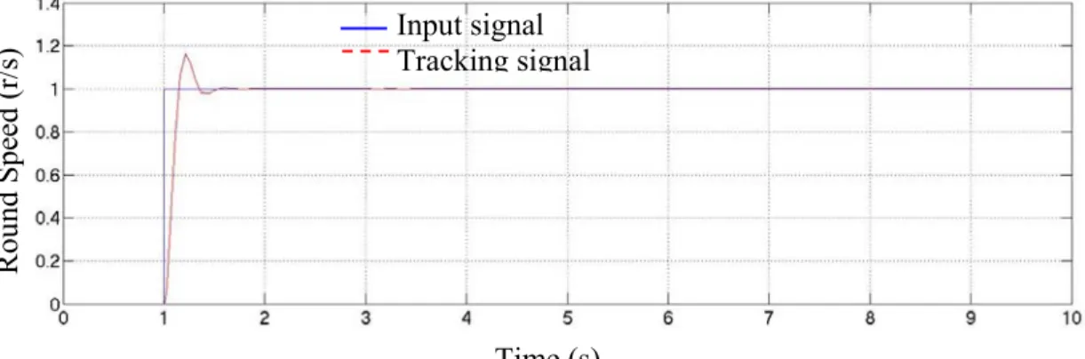
We do the numerical simulation in rotating motion for the robotic catheter system. Figure 2-13 shows the step/sinusoid controlling principle, Figure 2-14 shows the developed PID controller, the numerical simulation result with step input signal is shown in Figure 2-15, and the result of numerical simulation with sinusoid input signal is shown in Figure 2-16. When the neurosurgeon begins to operate the handle of master side, the input signal of the system is step signal, when the system is stable, the input signal of system is sinusoid signal, so the
30 Study on a Tele-operative Catheter System for Endovascular Neurosurgery
numerical simulation with step wave signal and sine wave signal was done.
Figure 2- 13 The control of the rotating motion
Chapter 2 The robot-assisted catheter system 31
Ph.D. thesis of Dr. Xu Ma
Time (s)
Figure 2- 15 System response with step input signal
Time (s)
Figure 2- 16 System response with sinusoid input signal
2.4 Realization of the control system
Based on above control strategy, we build the hardware for the robot-assisted catheter system to realize the control system, the flow diagram of the control system both on the master side and the slave side is shown in Figure 2-17, the control system for the catheter graspers on the slave side is shown in Figure 2-18, the control circuit of the master
Input signal Tracking signal Ro und Speed (r/ s) Input signal Tracking signal Rou nd Spe ed (r/ s)
32 Study on a Tele-operative Catheter System for Endovascular Neurosurgery
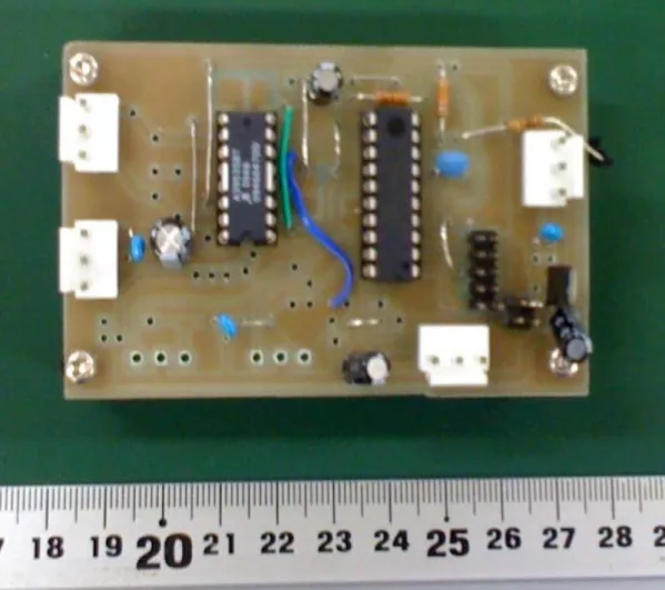
system is shown in Figure 2-19, the control circuit of the slave system is shown in Figure 2-20, both on the master system and slave system we used DSP (TI, TMS320F28335) as the control unit, the control circuit of catheter graspers is shown in Figure 2-21, in this circuit we used AVR (ATtiny 861) as the control unit.
Figure 2- 17 The control system (both master side and slave side)
Chapter 2 The robot-assisted catheter system 33
Ph.D. thesis of Dr. Xu Ma
34 Study on a Tele-operative Catheter System for Endovascular Neurosurgery
Chapter 2 The robot-assisted catheter system 35
Ph.D. thesis of Dr. Xu Ma
36 Study on a Tele-operative Catheter System for Endovascular Neurosurgery
2.5 The design of the feedback system
2.5.1 IntroductionAs we know, force information on the catheter is very important to insure the safety of an operation. Doctors always want to manage any details of an operation. The contact force between blood vessel and the catheter is a key detail. Stronger contact may get the blood vessel broken, so the method of getting the contact force information between the blood vessel and the catheter is urgent needed. There are two kinds of the contact force. One is generated when the side of the catheter contacts to the blood vessel, and the other one is generated when the end-tip contacts to the blood vessel. Both of them could cause damage during the operation. The conceptual diagram for measuring contact force is shown in Figure 2-22.
In this chapter, we developed a kind of feedback system to enhance the safety during operation, it includes two parts, one is the force feedback system, which provides the force feedback to neurosurgeon, let neurosurgeon to feel the contact force between catheter and blood vessel during operation. The other part is the visual feedback system, which provides the visual information to neurosurgeon during operation. We will introduce them in detail in this chapter.
Chapter 2 The robot-assisted catheter system 37
Ph.D. thesis of Dr. Xu Ma
Figure 2- 22 Measuring contact force and friction
2.5.2 Realization of the force feedback
We all know that the force information on the catheter is very important during the vascular interventional surgery, we developed a force feedback system for the developed robot-assisted catheter system, firstly, we designed a mechanism to measure the friction between catheter and blood vessel, the friction is also the neurosurgeon’s feeling force in real clinical vascular interventional surgery, further more, it is very important in order to let neurosurgeon feel the inserting force during operation by using the developed robot-assisted catheter system, the Figure 2-23 shows the feedback force measuring mechanism, the
38 Study on a Tele-operative Catheter System for Endovascular Neurosurgery
mechanism is assembled with the slave manipulator, the catheter supporting frame is linked to the load cell which is used to measure the inserting force on the catheter during operation. When the catheter grasper clamped the catheter, the catheter and the catheter supporting frame keep the same moving mode, it has no movement between them, further more, if the force is applied on catheter, the force will be transmitted to the catheter supporting frame, then the force was measured by the load cell which is linked to the catheter supporting frame, the measured force can be transmitted to the slave system, then transmitted to the master system and generated a haptic feedback to the neurosurgeon, the conceptual diagram of the transmission of the force feedback is shown in Figure 2-24.
Chapter 2 The robot-assisted catheter system 39
Ph.D. thesis of Dr. Xu Ma
Figure 2- 24 The transmission of force feedback
2.5.3 Realization of the visual feedback
The contact force between catheter tip and blood vessel and the situation of the operational scene is also important excepting the operating force information between catheter and blood vessel during the vascular interventional surgery, so how to get them and feedback them to the neurosurgeon is essential, we designed a visual feedback system to solve it. We used an IP camera which is shown in Figure 2-25
to monitor the situation the operational scene, we developed a user interface to monitor the contact force between catheter and blood vessel, the photograph of the developed user interface is shown in
Figure 2-26, the Figure 2-27 shows the transmission of visual feedback signal. As well as the force feedback, the visual feedback signal can be also transmitted to the neurosurgeon during the operation.
40 Study on a Tele-operative Catheter System for Endovascular Neurosurgery
Figure 2- 25 The IP camera for monitoring situation of operation (VIVOTEK FD8133V)
Chapter 2 The robot-assisted catheter system 41
Ph.D. thesis of Dr. Xu Ma
Figure 2- 27 The transmission of visual feedback signal
2.6 The performance evaluation
2.6.1 IntroductionIn order to verify the validity of the developed robot-assisted catheter system, we did the performance evaluation for the developed robot-assisted catheter system, the performance evaluation consists of evaluation of the master manipulator, evaluation of the slave manipulator, and the evaluation of the tracking performance, after the performance evaluation, we give the results for the evaluations, in this chapter, we will introduce the evaluating method and give the evaluating results, finally, we analyzed and discussed the evaluating results in detail.
2.6.2 Evaluation of the master manipulator
To evaluate the measurement precision of controller in master side, two experiments were carried out. One is to evaluate the measurement precision of axial movement and the other one for radial movement.
42 Study on a Tele-operative Catheter System for Endovascular Neurosurgery
The Figure 2-28 shows the evaluating system of the master manipulator.
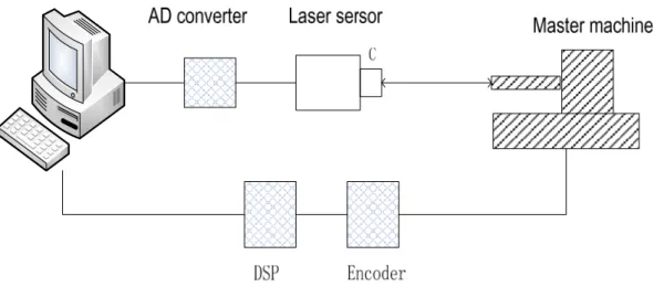
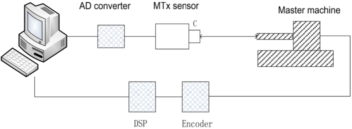
For the first experiment, we pulled and pushed the handle to make the movement stage go forward and backward for about 2 minutes, then measured the axial displacement by a laser sensor (KEYENCE Inc., LK-500, high precision mode, 10μm/mV). An A/D convert board (Interface Inc., PCI3329) was applied to get the displacement data to the computer (HP, z400), the sampling frequency was 100Hz. And at the same time, the measurement data of the controller was send to the same computer by serial port, the sampling frequency of the controller was set to 100Hz, baud rate of the serial port was set to 9600. After comparing these two groups of data, the axial measurement precision of the controller could be evaluated. The Figure 2-29 shows the evaluated method for axial precision. In the second experiment, radial measurement precision is evaluated. As well as the first experiment, we rotated the handle in clock wise and anti clock wise for 2 minutes, then measure the rotation angle by outside sensor and by the encoder couple to the handle of controller. A 3-axis inertial sensor (Xsens Inc. MTx, resolution 0.1 deg) is fixed on the handle to get the rotation angle. The sampling frequency of the inertial sensor is set to100Hz as the same as the controller. Sampling data of the controller was send to the computer by serial port, the Figure 2- 30 shows the evaluated method for radial precision.
Chapter 2 The robot-assisted catheter system 43
Ph.D. thesis of Dr. Xu Ma
Figure 2- 28 The evaluating system of the master manipulator
Figure 2- 19 The evaluated method for axial precision Figure 2- 29 The evaluated method for axial precision
44 Study on a Tele-operative Catheter System for Endovascular Neurosurgery
Figure 2- 20 The evaluated method for radial precision
2.6.3 Evaluation of the slave manipulator
To evaluate the measurement precision of the slave manipulator, the
Figure 2- 31 shows the evaluating system of the master manipulator, as well as evaluation of the master manipulator, there are also two experiments for evaluating the slave manipulator. The first experiment is to evaluate the axial movement precision. The slave manipulator was programmed to move along a reciprocating trace in axial. Then the actual displacement of the machine is measured by laser sensor. The second experiment is to evaluate the radial precision. We programmed the machine to make the catheter frame rotated back and forth. The actual rotation angle is measured by inertial sensor. In these two experiments, actual data and theoretical date were compared to obtain the precision of the slave manipulator.
Chapter 2 The robot-assisted catheter system 45
Ph.D. thesis of Dr. Xu Ma
Figure 2- 31 The evaluating system of the slave manipulator
2.6.4 Evaluation of the tracking performance
In this part, we did experiment to evaluate the tracking performance. In the experiment, we ignored the time delay between the master manipulator and slave manipulator. We just evaluate the tracking performance of the axial displacement and rotation. Firstly, we pulled and pushed the controller in master side from right end to left end then go back, we kept the axial displacement by laser sensor in both master manipulator and slave manipulator. To compare these two groups of data, the synchronization of the master manipulator could be obtained. The evaluating system of the tracking performance is shown in Figure
46 Study on a Tele-operative Catheter System for Endovascular Neurosurgery
2-32. This procedure was carried out for four times. Similarly, the synchronization of rotation could be obtained.
Figure 2- 32 The evaluating system of the tracking performance
2.6.5 Evaluated results
Both on the master side and the slave side, mean value and variance of the error between the laser sensor and the master manipulator are calculated. Similarly, we got mean value and variance of the error between the actual value and the theoretical value. The results are listed in Table 2-1 and Table 2-2. The precision evaluated result of the master manipulator is shown in Table 2-1, the precision evaluated result of the slave manipulator is shown in Table 2-2, Figure 2-33 shows the axial motion tracking curve, from Figure 2-33 we can know the movement
Internet C Master machine Laser/MTx sersor AD converter C Slave machine AD converter Laser/MTx sersor
Chapter 2 The robot-assisted catheter system 47
Ph.D. thesis of Dr. Xu Ma
curve of the master manipulator is fast than slave manipulator, it indicated that the lag exists. The lag time is going to be measured in the future. Figure 2-34 shows the radial motion tracking curve, as well as the master manipulator, lag could be found in Figure 2-34.
The Figure 2-33 shows the evaluated results of synchronization in axial direction. The master manipulator and slave manipulator are controlled by DSPs, DSPs communicate with each other with the Serial Peripheral Interface (SPI) port and RS422. The distance between the master manipulator and slave manipulator is about 5m. Based on the numbers of communication data and the distance, the SPI communication is fast enough to make the lag below 1ms in theory. However, from Figure 2-33 we can know the movement curve of the master manipulator is fast than slave manipulator, it indicated that the lag exists. The lag time is going to be measured in the future. We repeated the procedure for 4 times, Figure 2-35 shows a statistic result to evaluate the tracking precision. We have to align the data of two sides. The movement value is about 20ms. From the result in Figure 2-35, the axial error between master manipulator and slave manipulator are below 0.6mm, the standard deviation is below 1mm. Figure 2-34 shows the rotation tracking error. As well as the master manipulator, lag could be found in Figure 2-34. Figure 2-36 shows the statistics of the evaluated results. The mean error of the rotation is below 1.5o, but with a large standard deviation. It means a not stable radial motion. The
48 Study on a Tele-operative Catheter System for Endovascular Neurosurgery
mean overshoot mainly caused by the electromagnetic interface to the AD convertor which is used to drive the motor. The control circuit should be redesigned. And with different operator the radial tracking error is different because of the different rotation speed.
Table 2- 1 Precision evaluation result of master manipulator Master manipulator mean variance
Axial (mm) 0.35(0.35%) 0.025 Radial (deg) 3.1(1.72%) 2.1
Table 2- 2 Precision evaluation result of slave manipulator
Slave manipulator mean variance
Axial (mm) 0.23(0.23%) 0.04
Chapter 2 The robot-assisted catheter system 49
Ph.D. thesis of Dr. Xu Ma
Figure 2- 33 The axial motion tracking curve
50 Study on a Tele-operative Catheter System for Endovascular Neurosurgery
Figure 2- 34 The radial motion tracking curve
Chapter 2 The robot-assisted catheter system 51
Ph.D. thesis of Dr. Xu Ma
Figure 2- 35 The axial notion tracking statistic
52 Study on a Tele-operative Catheter System for Endovascular Neurosurgery
2.7 Summary
In this chapter, firstly, we design the mechanisms which constructed the structure of the master-slave for the robot-assisted catheter system in order to solve the aforementioned problems instructed in chapter 1. The master manipulator simulates the neurosurgeon’s operating skill and the slave manipulator driving the catheter to insert and rotate was developed in the slave system. We realized the communication based on RS 422 and internet between master system and slave system.
Secondly, we introduced the control system and realization of the hardware for the robot-assisted catheter system. We used a kind of PID control strategy to this system, and did the numerical simulation based on the developed PID control strategy both for the inserting motion and the rotating motion.
Then, we developed a feedback system including force feedback and visual feedback for this system. By using the developed feedback system, the neurosurgeon can know the contact information between catheter and blood vessel. According to the feedback system, the safety of the operation could be enhanced. In addition, the feedback system can replace the X-Ray, it can eliminate the radiation from X-ray to neurosurgeon.
Finally, the evaluation performance has been completed both master and slave. The evaluated results listed in Table 2-1 and Table 2-2 show
Chapter 2 The robot-assisted catheter system 53
Ph.D. thesis of Dr. Xu Ma
the precision of the catheter system, the precision of master manipulator measured is 0.35mm, and it has a very small variance. Rotation precision of the master manipulator is 3.1o with the variance of 2.1o. In the slave side, the precision of axial direction is 0.23mm and the rotation precision is 2.2o with a variance of 3.0o.
Chapter 3 Experiment by PID fuzzy control 55
Ph.D. thesis of Dr. Xu Ma
Chapter 3
Experiment by PID fuzzy control
3.1 Introduction
Increasing demands for flexibility and fast reactions in control method, fuzzy control (FC) can play an important role because the experience of experts can be combined in the fuzzy control rules to be implemented in the systems. We present a practical application of a fuzzy PID control to this developed system during the remote operations and compare with the traditional PID control experimentally. The feasibility and effectiveness of the control method are demonstrated. The synchronous manipulation performance with the fuzzy PID control is much better than using the conventional PID control method during the remote operations.
3.2 Fuzzy Control
Traditional control design methods use mathematical models of a system and its inputs to design controllers that analyse their effectiveness. FC uses fuzzy sets and fuzzy inference to derive control
56 Study on a Tele-operative Catheter System for Endovascular Neurosurgery
laws in which no precise model of the system exist, and most of the a priori information is available only in qualitative form. The basic idea of FC is to make use of expert knowledge and experience to build a rule base with linguistic rules. A fuzzy rule is a conditional statement, expressed in the form IF Then. There are two difficulties in designing any fuzzy logic control system: (1) the shape of the membership functions and (2) the choice of the fuzzy rules.
The proposed FC system is shown in Figure 3- 1 and the fuzzy controller operation, in general, is typically divided into the following three categories: fuzzification, inference engine and defuzzification. The fuzzification block means that real world variables are translated in terms of fuzzy sets. In a fuzzy inference engine, the control actions are encoded by means of fuzzy inference rules. The results of the fuzzy computations are translated in terms of real values for the fuzzy control action in the defuzzification block.
Chapter 3 Experiment by PID fuzzy control 57
Ph.D. thesis of Dr. Xu Ma
Figure 3- 1 General structure of fuzzy control
3.2.1 Input variables and normalization
The first step in FC is to take physical values of the system variables from the A/D converter and map them into a normalized domain. A fuzzy logic (FL) controller usually uses the error (e(k)) and the change of error (ce(k)) as the input variables.
( )
r( )
m( )
e k
=
y k
−
y
k
(Eq.3-1)( )
(
1)
( )
e k
e k
ce k
T
−
−
=
(Eq.3-2)58 Study on a Tele-operative Catheter System for Endovascular Neurosurgery
Where
y k
r( )
andy
m( )
k
are the reference and output, respectively,T
is the sampling period, ande
∈ −
[
l l
e, ]
e , ce∈ −[ l ld, ]d ,T
, le , dl
∈
R+, R+ denotes the set of all positive real values. To obtain the FC inputs, a reference value y kr( ) has to be determined, and the systemoutput ym( )k should be obtained from a sensor. Normalization of the
( )
e k
inputs andce k
( )
requires a scale transformation that maps thephysical values of the system variables into a normalized domain as:
( )
( )
N ee
k
=
k e k
(Eq.3-3)( )
( )
N dce
k
=
k ce k
(Eq.3-4)Where
k
e andk
d are the input scaling factors,e
N ,ce
N∈
[−L L, ], andk
e ,k
d ,L
∈
R
+
.
3.2.2 Fuzzification and membership functions
The membership functions used in the fuzzification play a crucial role in the final performance of a fuzzy control system, and the choice of the membership function has a strong influence on the control effect. There are several types of membership functions used in FC such as the triangular function, bell function, Gaussian function and trapezoidal
Chapter 3 Experiment by PID fuzzy control 59
Ph.D. thesis of Dr. Xu Ma
function. The triangular type membership function is most commonly used in FC applications because of its computational efficiency and simplicity.
3.2.3 Rule base
While the differential equations are the language of conventional control, IF-THEN rules about how to control the system are the language of fuzzy control, since an IF-THEN operator is the simplest and most widely used interpretation and, it provides computational efficiency. The control engineering knowledge method based on IF-THEN rules is the commonly used method to construct the rule base, since it needs more engineering skills and experience than plant information. Generally, the rules for the present problem are structured as:
i
r
: IFe
N isA
i and ceN isB
i THENu
fz isC
ijWhere
r
i denotes the fuzzy rules;i
=
1, 2,...,
n
, n is the number offuzzy rules; Ai and Bi denote input linguistic values from the fuzzy