Advance Publication by J-STAGE
日本機械学会論文集
Transactions of the JSME (in Japanese)
DOI:10.1299/transjsme.20-00431
Received date : 3 December, 2020
Accepted date : 19 March, 2021
スライダクランク連鎖を有する遠心振子式動吸振器による
ねじり振動の抑制に関する研究
劉
孝宏
*1,松﨑
健一郎
*2,中江
貴志
*1,尾﨑
純也
*3A study on torsional vibration suppression using centrifugal pendulum vibration absorber with
slider-crank chain
Takahiro RYU
*1, Kenichiro MATSUZAKI
*2, Takashi NAKAE
*1and Junya OZAKI
*3*1 Department of Innovative Engineering, Faculty of Science and Technology, Oita University
700Dannoharu, Oita-shi, Oita 870-1192, Japan
*2 Department of Mechanical Engineering, Kagoshima University, Kagoshima University
1-21-40 Korimoto, Kagoshima-shi, Kagoshima 890-0065, Japan
*3 Graduate School of Engineering, Oita University
700Dannoharu, Oita-shi, Oita 870-1192, Japan
Abstract
In recent years, high-power and low-cylinder engines are widely used. These engines produce a strong torsional vibration due to engine combustion in the powertrain. In automatic transmissions, a lock-up clutch which connects the engine and the gear train directly is operated in low engine rotation speed for fuel economy. The lock-up clutch operation in the low engine rotation speed causes the increase of vibration due to the resonance. To suppress the torsional vibration, a lock-up damper, a torsional spring, is attached in the torque converter. Centrifugal pendulum vibration absorbers (CPVA) are also developed for the countermeasure. However, the natural frequency of the CPVA varies in the large amplitude due to the nonlinearity, and large size of the centrifugal pendulum vibration absorber is needed to increase the suppressive effect. To overcome these problems, a new centrifugal pendulum vibration absorber with slider crank chain (SCDA) is invented. In this paper, the equation of motion of the SCDA is derived, and the suppressive effect of the SCDA is discussed theoretically. It is found that (1) the nonlinear natural frequency of SCDA can be designed almost linearly with its optimal link length ratio, (2) the SCDA with optimal link length ratio can suppress the vibration amplitude effectively, and (3) the suppressive effect of SCDA is larger than that of the CPVA.
Keywords : Vibration of rotating body, Automatic transmission, Torsional vibration, Centrifugal pendulum vibration absorber, Slider crank chain , Nonlinear vibration
1. 緒 言 エネルギー問題の高まりから,自動車業界では,低燃費化への技術開発が急加速されている.低燃費化実現の ため,4 気筒から 3 気筒,2 気筒化をも視野に入れた省気筒数化や気筒休止が進められている.また,自動車用オ ートマチックトランスミッション(以後,AT と呼ぶ)には,入力トルクを流体継手で変速機へ伝達するトルクコ ンバータ(以後,TC と呼ぶ)があり,常に入出力軸間の滑りを伴う.そのため,近年,ある回転数域から入出 力軸を直結するロックアップクラッチが多く採用されている.ロックアップクラッチでは,さらなる燃費向上の ため,高負荷低回転域でのロックアップを目指している.ところが,一方では,高級車志向によるエンジンの高 出力化も求められている.エンジンは,燃焼によるトルク変動のため,車軸系に強制ねじり振動をもたらす.そ のため,省気筒数化や低回転域でのロックアップは加振振動数低下による新たな共振問題を,高出力化は加振振
No.20-00431 [DOI: 10.1299/transjsme.20-00431]
*1 正員,大分大学 理工学部(〒870-1192 大分県大分市旦野原 700)
*2 正員,鹿児島大学 理工学域工学系(〒890-0065 鹿児島県鹿児島市郡元 1-21-40)
*3 学生員,大分大学大学院 工学研究科
幅増大の問題を生じており,それらの問題を解決するための新たな技術開発が急務となっている. ロックアップ時には,エンジンによるねじり振動が直接出力側に伝達されるため,TC 内には,ロックアップ ダンパと呼ばれるばねが配置されている.しかしながら,ロックアップダンパによる振動伝達の低減には限界が あるのが実情である.そこで,さらなる振動低減を図るため,TC 内に単振り子構造の遠心振子式動吸振器(以 後,遠心振子式動吸振器と呼ぶ)を取り付けたAT も実用化されている.遠心振子式動吸振器は,入力軸の回転 数に比例して固有振動数を追従させることができるため,エンジンなどの回転機械のねじり振動抑制に古くから 用いられている.遠心振子式動吸振器は,広い回転域でその制振効果を発揮できるものの,遠心振子の振幅に依 存した非線形性から,角変位が大きい場合に固有振動数が低下し,制振効果が低減する.そのため,遠心力場に
おける遠心振子単体の運動方程式が線形となるエピサイクロイド軌道型遠心振子(Rana and Joag, 2001)が広く用い
られている.しかしながら,これらの遠心振子式動吸振器を用いても,要求されたレベルの振動低減は実現でき ていない.特に,TC 内は,スペースの制限が厳しく,限られたスペースで効果的に作用する新たな吸振機構の 開発が望まれている. 遠心振子式動吸振器の研究は,国内では,遠心振子式動吸振器の非線形振動の理論的解析と実験に関する研究 (石田他,2005),遠心振子式動吸振器によるヘリコプタの制振に関する研究(長坂他,2010),エピサイクロイド軌 道に関する研究(相原他,2019)等がある.また,著者らは,遠心振子式動吸振器の軌道について多項式を用いた 最適化を理論的に行った(Ryu et al., 2019).一方,海外では,遠心振子式動吸振器の研究が盛んに行われており, 遠心振子の非線形振動に関する研究(Denman, 1992),遠心振子を物理振り子とした研究(Mitchiner and Leonard, 1991),複数の遠心振子式動吸振器の適用に関する研究(Chao et al., 1997),(Shi et al., 2013),(Issa and Shaw, 2015),
遠心振子にリンク機構を用いた研究(Mayet and Ulbrich, 2014),(Mayet and Ulbrich, 2015)等がある.物理振り子につ
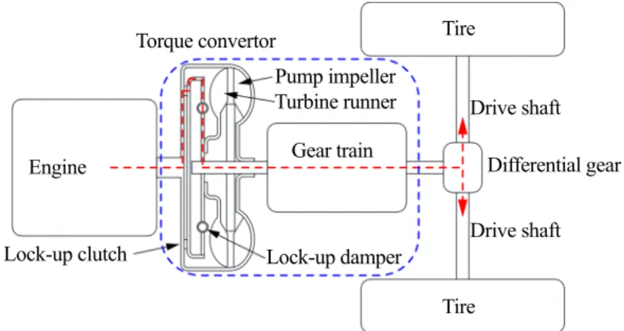
いては,慣性力の増大はあるものの,固有振動数の振幅依存性を調整することが難しく,リンク機構を用いた研 究においても,その最適な設計法については,論じられていない. そこで,本研究では,遠心振子式動吸振器にスライダクランク連鎖を併用した新たな遠心振子式動吸振器(以 後,スライダクランク式動吸振器と呼ぶ)を用いることにより,コンパクトかつ制振性能を増大可能な遠心振子 式動吸振器の設計法について,理論的に検証する. 2. 駆動系のモデリング 図1 は駆動系の概略図を示す.図中,青い破線内部が AT に相当する.ロックアップしていない場合,エンジ ンから入力されたトルクは,ポンプインペラーを回転させ,トルクコンバータ内部の流体力によりタービンラン
Fig. 1 Outline of car powertrain. The inside of the dashed blue line is the automatic transmission. When the lock-up clutch is operated, the input and output side of the torque converter is directly connected. Then the torque from the engine is transmitted through the red dashed line. The lock-up damper is attached in the torque convertor to reduce the torsional vibration caused by the engine combustion.
Lock-up damper Engine Tire Tire Drive shaft Drive shaft Gear train Differential gear Torque convertor Lock-up clutch Pump impeller Turbine runner
ナーが回転し,ギアトレイン,タイヤへと伝達される.このとき,ポンプインペラーとタービンランナーの間で 滑りが生じるため,燃費の低下につながる.そのため,ポンプインペラーとタービンランナーの回転速度が近く なると,ロックアップクラッチが作動し,トルクコンバータ内で入出力軸が直結される.図中の赤い破線がロッ クアップ時のトルクの伝達経路を示す. ロックアップクラッチ作動時には,エンジンの燃焼に起因したトルク変動によるねじり振動が直接パワートレ インに伝達されるため,車体全体に大きな振動を引き起こす.振動低減のため,ロックアップダンパと呼ばれる ばねが組み込まれているが,十分な制振効果が得られていない.そこで本研究では,エンジンの燃焼に起因した ねじり振動を効果的に低減するため,スライダクランク式動吸振器の最適設計法について理論的に検討を行う. 図2(a)および(b)は,図 1 に示した駆動系のねじり振動の解析モデルである.図 2(a)は,駆動系の詳細モデルで あり,赤い破線の内側がトルクコンバータである.駆動系はエンジン,トルクコンバータ内部の3 つの部材(TC1, TC2,TC3)からからなる 4 自由度系でモデル化した.なお,TC3,ギアトレインおよびディファレンシャルギア は一体とし,タイヤは固定とする.それぞれの慣性モーメントをJ , 1 J , 2 J および3 J ,角変位を4 1, 2, 3お よび4とする.また,各部材を接合する回転ばねの回転ばね定数をK , 1 K , 2 K および3 K ,回転方向の粘性減4 衰係数をC , 1 C , 2 C および3 C とする.エンジンには,爆発 1 次成分に相当するトルク振幅T および角振動数4 の加振トルクTcos が作用している.エンジンの気筒数をt i,クランク軸の回転角速度をとすると,次式の 関係が得られる. 2 i Ω (1) 動吸振器は,3の位置に取り付ける.スライダクランク式動吸振器の基本性能を評価するため,以下では,図 2(a)の振動系について減衰を0 とおいてモード解析し,ターゲットとなるモードの1 自由度系に対する制振効果 を検証する(背戸他,1984).図2(b)は,動吸振器取り付け位置で正規化したモード行列を用いたモード解析後の1 自由度モデルである.T Jd, およびK はそれぞれモード解析後の加振トルク,慣性モーメントおよび回転ばね定 数である.粘性減衰係数Cは,図2(a)におけるモード減衰比が一致するように定める. は制振対象の角変位を 表す.この1自由度モデルに対し,遠心振子式動吸振器やスライダクランク式動吸振器の制振性能を評価する.
(a) 4-dof model (b) 1-dof model Fig. 2 Analytical model of car powertrain. The car powertrain is modelled by 4-dof model. The modal analysis is applied to the
4-dof model. A target vibration mode is selected, and the suppressive effect of the dynamic absorber is evaluated by using the 1-dof model.
3. 理論解析 3・1 遠心振子式動吸振器 回転体に装着した遠心振子の固有振動数は,回転体の回転数に応じて変化する.エンジンのように加振振動数 が回転数に比例して変化する系に対し,加振振動数にチューニングした遠心振子式動吸振器を取り付けることで, ねじり振動を効果的に低減させることができる.本節では,スライダクランク式動吸振器の制振性能と比較する ため,一般的な円軌道の遠心振子式動吸振器を取り付けた場合について検討する. Torque convertor 1 2 3 4 4 J 3 J 2 J 1 J cos T t 2 C C3 C4 1 K K2 K3 K4 Engine Drive shaft TC1 TC2 TC3
Differential gear Tire
K C cos d T t J 1 C
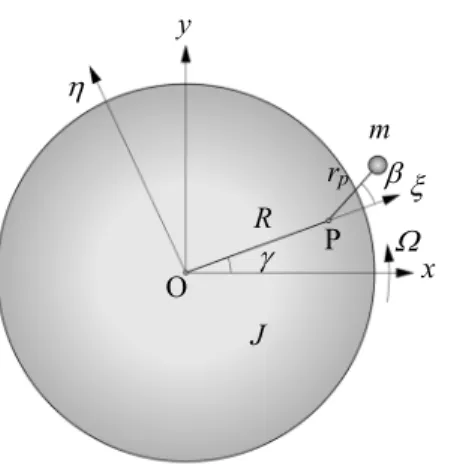
図3は,図2(b)の1自由度モデルに遠心振子式動吸振器を取り付けた解析モデルを示す.制振対象(以後,主
系と呼ぶ)の回転中心Oから半径R の点Pに,長さrp,質量m の遠心振子が取り付けられている.
Fig. 3 Analytical model of centrifugal pendulum vibration absorber(CPVA). The CPVA with mass m and pendulum length r p
is attached on the rotating circular plate.
点O を原点とする角速度で回転する回転座標系をO xy とする.定常回転からの主系の角変位を とし,
主系に固定された回転座標系をOとする.軸は,OPと同じ向きであり,軸からの遠心振子の角変位を
とする.主系および遠心振子式動吸振器の運動方程式は次式となる.
2 2 2
{J m R ( rp 2Rrpcos )} m r( p Rrpcos ) mRrp (2 2 )sinCK Tdcost (2)
2 2 2 ( p pcos ) p p p( ) sin 0 m r Rr mr c mRr (3) ここに,cpは に比例した粘性減衰係数である. 減衰がない場合の遠心振子式動吸振器単体の運動方程式は, 2 2sin 0 p p mr mRr Ω (4) を微小として,式(4)を線形化すると遠心振子単体の固有振動数 が求められる.p , p p p R Ω n Ω n R r r (5) 上式は遠心振子の角変位が微小の範囲で運動しているとき,固有振動数が回転数のn 倍になることを示してお り,n を次数と定義する.式(1)および式(5)から,次数n i / 2とすれば,回転上昇とともに,常に固有振動数 と加振振動数を一致させることができる.式(2)および式(3)を無次元化すると次式となる.
(1Rr2Rrcos ) (rRrcos ) Rr (2 2)sin2 cos (6)
2 (rRrcos ) r 2 p Rr( ) sin 0 (7) R m p r J x y O P
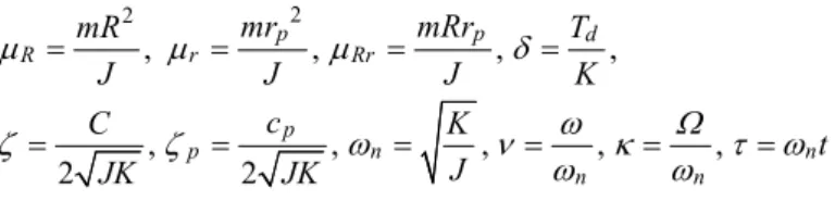
ここに, 2 2 , , , , , , , , , 2 2 p p d R r Rr p p n n n n mr mRr mR T J J J K c C K t J JK JK (8) であり,(´)は による微分を表す. 3・2 スライダクランク式動吸振器 図4 は,スライダクランク式動吸振器の解析モデルである.特に断りがない限り,遠心振子式動吸振器と同じ 変数を用いることとする.スライダクランク式動吸振器は,主系と同心円上に,主系に対し回り対偶で拘束され た慣性モーメントJ のイナーシャリングが配置されており,主系上に質量 m のスライダが設置されている.イp ナーシャリング上の半径R の点 P と,スライダ上の点 Q にそれぞれまわり対偶がある.PQ の長さをr とする.p イナーシャリングの軸からの角変位を ,点 P における外角をとする.点O から,スライダまでの距離を r とすると,リンクの幾何学的関係から, cos pcos( ) rR r , Rsin rpsin( ) (9)
Fig. 4 Analytical model of centrifugal pendulum vibration absorber with slider crank chain(SCDA). The SCDA consists of a slider with mass m on the main system and a inertia ring with inertial J which is connected by links. p
点Q の速さを v とすると, 2 2 2( )2 v r r (10) 系全体の運動エネルギーT およびポテンシャルエネルギーU は, 2 2 2 2 1 1 1 1 ( ) ( ) , 2 2 p 2 2 T J J mv U K (11) 主系および動吸振器の減衰を考慮してラグランジュの運動方程式を用いると,系の運動方程式は次式となる. 2 2 2 (J J pmr )Jp Jp 2mrr ( ) CK Tdcost (12) R rp y x m J p J O P Q r
2 2 2 2 2 2 ( ) ( ) ( ) 0 p p p p J J mr J mr r c mrr (13) ここに, d r r d , d d , 2 2 d r2 r d , 2 2 d 2 d (14) 減衰がない場合のスライダクランク式動吸振器単体の運動方程式は, 2 2 2 2 2 2 (Jpmr)(Jp mr r ) mrr 0 (15) 平衡点では, となり,平衡点近傍では, 0 , ( ), p , p p p p p Rr r r R r R r r R r R r (16) 式(12),(13)を線形化すると,次式のようになる. 2 { p ( p) } p p dcos p r J J m R r J C K T t R r (17) 2 2 0 p p p p p p p p r r J J c mRr R r R r (18) 不減衰の線形化された遠心振子単体の運動方程式および固有振動数 は次式となる. p 2 2 0 p p p p r J mRr R r (19) 2 2 ( ) ( ) , p p p p p p p mR R r mR R r n n J r J r (20) ここに,n はスライダクランク式動吸振器の次数である.式(20)から,動吸振器の慣性項としてイナーシャリ ングの慣性モーメントが作用し,復元力項としてスライダの質量が作用している.遠心振子式動吸振器と比較す ると制振メカニズムが異なっており,制振効果が期待できる.また,式(5)と比較すると,線形の固有振動数は, スライダの質量やイナーシャリングの慣性モーメントでも調整可能であることがわかる.これらが,スライダク ランク式動吸振器の大きな特徴である. 式(12)および式(13)を無次元化すると次式となる. 2 1 2 2 (1pr ) p p 2r ( ) 2 cos (21) 2 2 2 3 2 4 2 ( ) ( ) 2 ( ) 0 p p r p r p r (22) ここに, 2 2 2 1 2 3 4 , , , , p p mr J mr mrr mr r r r r r J J J J J (23)
4. 数値計算結果 エンジンの気筒数をi とすると,式(1)から,ねじり振動の加振振動数は,4 2となるため,次数をn2 とした.表1 は,図 1(a)の実車解析モデルから得られた固有振動数である.固有振動数と合わせて共振点の回転 数(rpm 値)を示している.実車の性能評価範囲は 900~2000 rpm であり,2 次の固有振動数が領域に含まれてい ることがわかる.そこで,2 次モードを制振対象モードとして選択した.周波数応答曲線の計算には,Shooting 法を用いた.なお,本論文では,周波数応答は定常応答として評価する.事前の数値計算の結果から,遠心振子 の減衰は,制振効果をやや鈍くする効果があることがわかった.以下の数値計算では,遠心振子式動吸振器およ びスライダクランク式動吸振器の基本性能の評価を比較する観点から,遠心振子の減衰は0 として取り扱った.
Table 1 Natural frequencies.
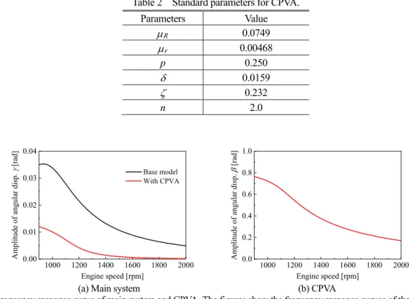
1st 2nd 3rd 4th Natural frequency [Hz] 9.71 32.6 81.8 240 Engine speed [rpm] (i4) 291 986 2450 7190 4・1 遠心振子式動吸振器の制振効果 表2 は,遠心振子式動吸振器の基準パラメータを示す.表中の p はリンク長比rp/R である.本解析では,ス ライダクランク式動吸振器が,動吸振器として運動可能なパラメータ値を選定しており,スライダの半径方向お よびイナーシャリングの円周方向の運動を制限する幾何学的拘束は考慮していない.図5 は,遠心振子式動吸振 器を取り付けていない場合および式(6)および(7)から求めた遠心振子式動吸振器を取り付けた場合の周波数 応答曲線を示す.図5(a)の黒色実線は遠心振子式動吸振器を取り付けていない場合(Base model),赤色実線は遠 心振子式動吸振器を取り付けた場合の結果である.また,図5(b)は,遠心振子の角変位を示す.図から,遠心振 子式動吸振器を取り付けることにより,振幅が低減されていることがわかる.回転数の小さい領域では,遠心振
Table 2 Standard parameters for CPVA. Parameters Value R 0.0749 r 0.00468 p 0.250 0.0159 0.232 n 2.0 1000 1200 1400 1600 1800 2000 0.00 0.01 0.02 0.03 0.04 Amplitude of angular di sp. [r ad ] Engine speed [rpm] Base model With CPVA 1000 1200 1400 1600 1800 2000 0.0 0.2 0.4 0.6 0.8 1.0 A m pli
tude of angular disp.
[rad]
Engine speed [rpm]
(a) Main system (b) CPVA
Fig. 5 Frequency response curve of main system and CPVA. The figures show the frequency response curves of the main system and CPVA when the CPVA is attached. The frequency response curve of the base model without CPVA is also calculated. The amplitude of the main system is suppressed by attaching the CPVA.
0.8 0.9 1.0 1.1 1.2 0.0 0.2 0.4 0.6 0.8 1.0 1.2 1.4 1.6 A m plitude of [r ad ] Frequency ratio q
Fig. 6 Relationship between frequency ratio and angular displacement of CPVA. The nonlinear natural frequency becomes smaller than the linear natural frequency when the vibration amplitude of the CPVA is large.
子が大きく揺れている.図6 は,式(4)から求めた遠心振子式動吸振器の非線形固有振動数と線形固有振動数と の比q と遠心振子の振幅の関係を示す.図6 から,遠心振子の振幅が大きくなると,非線形固有振動数は,大き く低下することがわかる.図5(b)の遠心振子の振幅から,低回転域では,線形の固有振動数から大きくずれた状 態で振動していることがわかる. 4・2 スライダクランク式動吸振器の制振効果 スライダクランク式動吸振器は,リンク長,スライダの質量およびイナーシャリングの慣性モーメントなど, 遠心振子式動吸振器と比較して,振動特性を決定するためのパラメータが多い.そこで,パラメータを決定する ために,まず,自由振動特性を調査した.リンクの全長およびスライダの質量は,遠心振子式動吸振器と同一と した.リンク長比p をパラメータとし,式(20)からn を満たすイナーシャリングの慣性モーメント2 J を決定p した.図7 は,表 3 に示す 3 種類のパラメータ値における式(15)から求めた自由振動特性である.青色,橙色
Table 3 Standard parameters for SCDA.
Parameters Type 1 Type 2 Type 3
R 0.0781 0.0875 0.0976 r 0.00392 0.00213 0.000876 p 0.131 0.187 0.309 p 0.224 0.156 0.0947 0.0159 0.232 n 2.0 0.8 0.9 1.0 1.1 1.2 0.0 0.2 0.4 0.6 0.8 1.0 1.2 1.4 1.6 Am plit ude of [rad ] Frequency ratio q Type 1 Type 2 Type 3 CPVA
Fig. 7 Relationship between frequency ratio and angular displacement of SCDA. The nonlinear natural frequency characteristics can be controlled by the link length ratio of SCDA.
および緑色の実線がそれぞれType 1~Type 3 の結果である.また,図 6 の遠心振子式動吸振器の結果も赤色破線 で合わせて示している.図7 から,リンク長比 p を調整することにより,固有振動数の振幅依存性が変わってい ることがわかる.図から,Type 2 の固有振動数の振幅依存性が最も小さい.そこで,Type 2 の近傍で,できるだ け固有振動数が振幅に依存しないリンク長比を探索する. 非線形固有振動数と線形固有振動数とのずれは振幅に依存するため,設定したずれの割合の振幅に対する平均 値Q[%]をあらかじめ定め,その平均値がQ 以下となる最大振幅0を評価基準とする.非線形固有振動数が線 形の固有振動数に近いほど0が大きい値となる.図8(a)は,図 7 の Type 2 を例にとり,評価方法を示した図であ る.横軸はずれの割合100 1q [%],縦軸は振幅である.この場合,例えばQ4 %と設定すると,図 8(a)の 網掛部の平均値が4%となり,その時の最大振幅0は1.35 rad となる.図 8(b)は,Type 2 近傍のリンク長比 p に おいて,線形固有振動数とのずれQをそれぞれ0.02 %,0.06 %および 0.10 %と設定したときの最大振れ角0の 値を,式(15)から求めた結果である.図中,横軸はリンク長比 p ,縦軸は最大振れ角0である.青色,赤色お よび黒色の実線がそれぞれQを0.02 %,0.06 %および 0.10 %に設定したときの結果である.図 8(b)から,p=0.137 付近で,最大振れ角0が大きな値をとっており,リンク長比には最適値があることがわかる.そこで,基準パラ 0 10 20 30 0.0 0.2 0.4 0.6 0.8 1.0 1.2 1.4 1.6 Ampl itude of [ rad] 100|1q| [%] Q 0 0.13 0.14 0.15 0.16 0.17 0.18 0.0 0.2 0.4 0.6 0.8 1.0 1.2 1.4 1.6 Maximum ampli tude of 0 [r ad ] p 0.02 % 0.06 % 0.10 %
(a) Detuning of natural frequency (b) Maximum amplitude of 0
Fig. 8 Relationship between the link length ratio and tuning of nonlinear natural frequency. When the link length ratio p is about
0.137, the frequency ratio is almost kept at 1.0 in the wide range of angular displacement .
Table 4 Optimum parameters. R 0.0905 r 0.00170 p 0.0213 p 0.137 0.0159 0.232 n 2.0 0.8 0.9 1.0 1.1 1.2 0.0 0.2 0.4 0.6 0.8 1.0 1.2 1.4 1.6 A m plitude of [r ad ] Frequency ratio q
Fig. 9 Relationship between frequency ratio and angular displacement of SCDA. This is the result when the link length ratio 0.137
p . The nonlinear natural frequency is almost equal to the linear natural frequency in wide range of angular displacement of SCDA.
メータとしてp=0.137 を採用することとした.表 4 に採用した基準パラメータを示す. 図9 は,表 4 のパラメータを使用した場合の式(15)から求めた自由振動特性を示す.図から,固有振動数比 がほぼ線形に保たれており,大きな制振効果が期待できる.リンク長比の調整により,非線形固有振動数を調整 可能なところも,スライダクランク式動吸振器の特徴の一つである. 図10(a), (b)はそれぞれスライダクランク式動吸振器を取り付けた場合の主系および動吸振器の周波数応答曲線 を,式(21)および(22)を用いて求めた結果である.図 10(a)から,最適値における応答振幅が最も小さくなっ ており,制振効果が高いことがわかる.また,図10(b)から,遠心振子の角変位は最大で 0.8rad 付近を示しており, その角変位における線形固有振動数からの誤差は図8 より 0.02%未満であるため,常用回転数域においておよそ 誤差なく運用できることがわかる. 図11 は,図 10 のエンジン回転数 900 rpm における最適化されたスライダクランク式動吸振器の角変位 お, よび を,式(21)および(22)を用いて求めた結果である.横軸は,強制振動の 1 周期である.スライダクラ ンク式動吸振器を取り付けることにより,主系の角変位 がほぼ 0 に抑えられていることがわかる. 図12 は,図 11 の角変位をスライダクランク式動吸振器の動きとして表した図である.図には,強制振動の 1/8 1000 1200 1400 1600 1800 2000 0.000 0.005 0.010 0.015 A m pli tud e of an gular disp. [rad] Engine speed [rpm] Type1 Type2 Type3 Optimum CPVA 1000 1200 1400 1600 1800 2000 0.0 0.2 0.4 0.6 0.8 1.0
Amplitude of angular disp.
[rad] Engine speed [rpm] Type1 Type2 Type3 Optimum CPVA
(a) Main system (b) SCDA
Fig. 10 Frequency response curve of main system and SCDA. The figures show the frequency response curves of the main system and SCDA when the SCDA is attached. The frequency response curve with CPVA is also calculated. The amplitude of the main system is extremely suppressed by attaching the SCDA. The amplitude of the angular displacement of the main system is the smallest when the optimum SCDA is attached.
-1.0 -0.8 -0.6 -0.4 -0.2 0.0 0.2 0.4 0.6 0.8 1.0 Angular disp. , , [ra d] t [rad] 0 2
Fig. 11 Angular displacements of optimum SCDA when engine speed is 900 rpm. This figure shows the angular displacements of ,
and of the optimum SCDA when the engine speed is 900 rpm. The abscissa shows one period of the forced vibration. The vibration of the main system is almost suppressed by the SCDA.
Fig. 12 Movement of optimum SCDA when engine speed is 900 rpm. This figure shows the movement of the links of the optimum SCDA when the engine speed is 900 rpm. The half period of the vibration is shown.
P Q R O p r
0.120 0.125 0.130 0.135 0.140 0.145 0.150 0.155 0.0000 0.0005 0.0010 0.0015 0.0020 0.0025 0.0030 0.0035 0.0040 M aximu m amp litu de [rad ] p m=const. Jp=const.
Fig. 13 Relationship between link length ratio and the maximum amplitude of main system. The black and red lines shows the results when the constant value is mass m and inertia J . There is a optimum value of link length ratio to suppress the p
maximum amplitude of the main system. The optimum value of p is close to the optimum value which is given by the free vibration analysis.
周期ごとの動きを示してあり,半周期の動きを重ねて表示している.残りの半周期もほぼ同じ動きである.図か ら,イナーシャリングの動きとスライダの動きが連動して,制振されている様子がわかる. これまでの数値計算により,最適化されたスライダクランク式動吸振器は,非線形固有振動数と次数とのずれ を最小化するように設計し,主系の振幅が低減されることがわかった.この設計法は,主系の振幅低減に対する 最適値を求めたものではないため,主系の振幅低減に対しても適切な評価基準になっているかどうかを確認する 必要がある.そこで,表4 のパラメータを基準に,pを変化させた場合の評価回転域(900~2000 rpm)における 応答振幅の最大値を,式(21)および(22)を用いて求めた.その結果を図 13 に示す.図 13 の黒色実線はスラ イダの質量m を固定しイナーシャリングの慣性モーメントJpを次数に合わせて調節した場合,赤色実線はJpを 固定しm を次数に合わせて調整した結果である.また青色破線は固有振動数評価による最適設計である表4 のp を表す.図13 から,両者ともに,本解析で得られたパラメータ値付近で最小値を示しており,主系の応答振幅に 対しても,ほぼ最適値化を図ることができる.なお,最適値のわずかなずれは,主系に取り付けられた動吸振器 が式(21)および(22)に示すように,非線形的に連成することに起因している.以上から,スライダクランク 式動吸振器の最適設計は,非線形固有振動数と次数とのずれを最小化するように設計すれば,効果的な振動低減 が図れることがわかった.なお,紙幅の都合上省略したが,本論文で使用したパラメータ値の範囲において,3 気筒エンジン(n1.5)においても定性的に同様の設計法が適用できることを確認している. 本論文では,スライダクランク式動吸振器の基本性能を評価するため,スライダ等の摩擦やガタの影響を考慮 していないが,それらの影響を考慮した実用的評価に関しては,今後の課題としたい. 5. 結 言 本研究は,実機のオートマチックトランスミッションをモード解析により低次元化したモデルを使用して,ス ライダクランク連鎖を備えた遠心振子式動吸振器について,理論的に最適設計法を検討した.その結果は以下の ようにまとめられる. (1)スライダクランク式動吸振器について,運動方程式を導出することにより,線形の固有振動数を求めること ができた. (2)スライダクランク式動吸振器の非線形固有振動数は,リンク長比を変化させることにより,振動振幅に対す る固有振動数ずれを調整することができる. (3)自由振動特性をもとに非線形固有振動数と線形固有振動数との誤差をできるだけ小さくした最適パラメータ 値で設計されたスライダクランク式動吸振器を用いることで,制振対象に対して高い制振効果が得られた. (4)提案した最適設計法は,制振対象の応答振幅に対してもほぼ最適化されている. (5)摩擦やガタの影響および加減速時の過渡応答に関するスライダクランク式動吸振器の評価は今後の課題であ る.
謝 辞
本研究はJSPS 科研費 JP18H01396 の助成を受けたものです.
文 献
相原建人,渡邊啓太,土肥永生,金子祥平,遠心振子式動吸振器のねじり振動低減性能に関する理論解析-エピ
サイクロイド軌道の定式化とMBD モデルによる検証-,自動車技術会論文集,Vol.50, No.2 (2019), pp.353-358.
Chao, C. P., Lee, C. T. and Shaw, S. W., Non-unison dynamics of multiple centrifugal pendulum vibration absorbers, Journal of Sound and Vibration, Vol. 204, No. 5 (1997), pp.769-794.
Denman, H. H., Tautochronic bifilar pendulum torsion absorbers for reciprocating engines, Journal of Sound and Vibration, Vol. 159, No. 2 (1992), pp.251-277.
石田幸男,井上剛志,賀川泰史,上田元彦,遠心振り子式動吸振器を取り付けた回転軸系の非線形振動解析とね じり振動の制振,日本機械学会論文集C 編,Vol. 71, No. 708 (2005), pp.2431-2438.
Issa, J. S. and Shaw, S. W., Synchronous and non-synchronous responses of systems with multiple identical nonlinear vibration absorbers, Journal of Sound and Vibration, Vol. 384 (2015), pp.105-125.
Mayet, J. and Ulbrich, H., First-order optimal linear and nonlinear detuning of centrifugal pendulum vibration absorbers, Journal of Vibration and Acoustics, Vol. 335 (2015), pp.34-54.
Mayet, J. and Ulbrich, H., Tautochronic centrifugal pendulum vibration absorbers General design and analysis, Journal of Vibration and Acoustics, Vol. 333 (2014), pp.711-729.
Mitchiner, R. G. and Leonard, R. G., Centrifugal pendulum vibration absorbers - theory and practice, Journal of Vibration and Acoustics, Vol. 113 (1991), pp.503-507.
長坂今夫,石田幸男,小山貴之,藤松直樹,振子式動吸振器によるヘリコプタの制振(ブレードの弾性1 次モー
ド),日本機械学会論文集C 編,Vol. 76, No. 765 (2010), pp.1148-1154. Rana, N. C. and Joag, P. S., Classical Mechanics (2016), p.232, McGraw-Hill.
Ryu, T., Nakae, T., Matsuzaki, K. and Ozaki, J., Fundamental study on the optimal path of centrifugal pendulum vibration absorber in automatic transmissions, Materials Science and Engineering, Vol. 670 (2019), pp.1-5.
背戸一登,岩波孝一,滝野好宏,動吸振器による多自由度系の制振(第1 報,動吸振器の設計理論),日本機械学
会論文集C 編,Vol. 50, No. 458 (1984), pp.1962-1969.
Shi, C., Parker, R. G. and Shaw S. W., Tuning of centrifugal pendulum vibration absorbers for translational and rotational vibration reduction, Mechanism and Machine Theory, Vol. 66 (2013), pp.56-65.
References
Aihara, T., Watanabe, K., Dohi, N. and Shohei, K., Theoretical analysis for torsional vibration reduction performance of CPVA - Foumulation of epicycloid path and verification by MBD model -, Transactions of the Society of Automotive Engineers of Japan, Vol.50, No.2 (2019), pp.353-358 (in Japanese).
Chao, C. P., Lee, C. T. and Shaw, S. W., Non-unison dynamics of multiple centrifugal pendulum vibration absorbers, Journal of Sound and Vibration, Vol. 204, No. 5 (1997), pp.769-794.
Denman, H. H., Tautochronic bifilar pendulum torsion absorbers for reciprocating engines, Journal of Sound and Vibration, Vol. 159, No. 2 (1992), pp.251-277.
Ishida, Y., Inoue, T., Kagawa, T. and Ueda, M., Nonlinear analysis of torsional vibration of a rotor with centrifugal pendulum vibration absorbers and its suppression, Transactions of the Japan Society of Mechanical Engineers, Series C, Vol. 71, No. 708 (2005), pp.2431-2438 (in Japanese)..
Issa, J. S. and Shaw, S. W., Synchronous and non-synchronous responses of systems with multiple identical nonlinear vibration absorbers, Journal of Sound and Vibration, Vol. 384 (2015), pp.105-125.
Mayet, J. and Ulbrich, H., First-order optimal linear and nonlinear detuning of centrifugal pendulum vibration absorbers, Journal of Vibration and Acoustics, Vol. 335 (2015), pp.34-54.
Mayet, J. and Ulbrich, H., Tautochronic centrifugal pendulum vibration absorbers General design and analysis, Journal of Vibration and Acoustics, Vol. 333 (2014), pp.711-729.
Mitchiner, R. G. and Leonard, R. G., Centrifugal pendulum vibration absorbers - theory and practice, Journal of Vibration and Acoustics, Vol. 113 (1991), pp.503-507.
Nagasaka, I., Ishida, Y., Koyama, T. and Fujimatsu, N., Vibration suppression of a helicopter by pendulum absorbers (First elastic mode of blades), Transactions of the Japan Society of Mechanical Engineers, Series C, Vol. 76, No. 765 (2010), pp.1148-1154 (in Japanese).
Rana, N. C. and Joag, P. S., Classical Mechanics (2016), p.232, McGraw-Hill.
Ryu, T., Nakae, T., Matsuzaki, K. and Ozaki, J., Fundamental study on the optimal path of centrifugal pendulum vibration absorber in automatic transmissions, Materials Science and Engineering, Vol. 670 (2019), pp.1-5.
Seto, K., Iwanami and K., Takita, Y., M., Vibration control of multi-degree-of-freedom systems by dynamic absorbers (1st Report, On the design method for dynamic absorbers), Transactions of the Japan Society of Mechanical Engineers, Series C, Vol. 50, No. 458 (1984), pp.1962-1969 (in Japanese).
Shi, C., Parker, R. G. and Shaw S. W., Tuning of centrifugal pendulum vibration absorbers for translational and rotational vibration reduction, Mechanism and Machine Theory, Vol. 66 (2013), pp.56-65.