Study on Mechanical Properties of Braided CFRP
著者 ナナン エンドリアトノ
著者別表示 Nanang Endriatno journal or
publication title
博士論文本文Full 学位授与番号 13301甲第4822号
学位名 博士(工学)
学位授与年月日 2018‑09‑26
URL http://hdl.handle.net/2297/00053065
Creative Commons : 表示 ‑ 非営利 ‑ 改変禁止 http://creativecommons.org/licenses/by‑nc‑nd/3.0/deed.ja
DISSERTATION
Study on Mechanical Properties of Braided CFRP
Graduate School of Natural Science and Technology Kanazawa University
Division of Mechanical Science and Engineering
Student ID Number Name
Chief Advisor Date of Submission
: 1524032020 : Nanang Endriatno
: Prof. Toshiyasu KINARI : 2018.6.25
ii Abstract
This thesis investigates the hoop and bending properties of braided CFRP cylinders with different braiding angles and number of layers under internal pressure and bending load respectively. In recent years, carbon fiber reinforced plastic (CFRP) materials have been used in the repair and strengthening of structures. In the first set of experiments braided preformed CFRP applied on a steel cylinder subjected to internal pressure were experimentally investigated using simplified methods of combining thin cylinders. Braided preformed CFRP with different braiding angles and numbers of applied layers were analyzed. From measurements of internal pressure, the elastic modulus and hoop stress was estimated. High braiding angles had a small deviation for values of the elastic modulus which is more stable against high internal pressure in the hoop direction. Similar results were observed when additional layers were applied. It was found that specimens braided at 75 had the highest elastic modulus value, followed by those at 60 and at 45. For cylinders with different numbers of layers, the highest elastic modulus value occurred with 4 layers, followed by those for 3 layers and 2 layers. On the other hand, the addition of CFRP can provide effective pressure contact to withstand internal loads from inside the pipe. Increasing the braiding angle and the number of layers can reduce the hoop stress on a cylinder under internal pressure.
The braiding process also offers the possibility to enhance the bending properties with changing the braided structures. In the second set of experiments braided structures were produced using a circular braiding machine with 3 braiding angles (15, 45, and 60) and 3 layering levels (1, 2, and 3 layers) with the insertion of a neutral yarn. Braided CFRP were made by the vacuum assisted resin transfer molding (VaRTM) method and tested by 3 point bending test. It was found that the different braiding structure influenced the bending properties. As the number of layers increased, both the bending modulus and maximum load tended to increase. As the braiding angle decreased, the direction of the fibers became closer to the axial direction so that the bending modulus tended to increase. In contrast, as the braiding angle increased, the fiber volume fraction increases so that the maximum load showed a tendency to increase. The presence of the neutral yarn, tended to increase both the bending modulus and maximum load.
Keyword: Carbon Fiber Reinforced Plastic, Braid, Elastic Modulus, Hoop Stress, Bending Properties
iii
TABLE OF CONTENTS
Chapter 1. Introduction
1.1. Background ... 1
1.2. Objectives ... 5
1.3. Structure of Thesis ... 5
Chapter 2. Literature Review 2.1. Composite Materials ... 6
2.1.1. Introduction to composites ... 6
2.1.2. Textile composites ... 6
2.1.3. Braided fabric ... 7
2.1.4. Carbon fiber reinforced plastics (CFRP) ... 8
2.2. Manufacturing of Braided Composites ... 9
2.2.1. Braiding parameter ... 10
2.2.2. Braiding process ... 10
2.2.3. Vacuum assisted resin transfer molding (VaRTM) ... 12
2.2.4. Determination of fiber volume fraction ... 14
Chapter 3. Experimental Study on Hoop Stress Affecting Braided Carbon Fiber Reinforced Plastics Subjected to Internal Pressure 3.1. Hoop Stress on The Pressure Vessel Subjected to Internal Pressure ... 15
3.2. Experimental Procedure ... 19
3.2.1. Test specimen and manufacturing ... 19
3.2.2. Pressurized oil testing method ... 23
3.3. Determination of Elastic Modulus ... 25
3.3.1. Elastic modulus of steel ... 25
3.3.2. Elastic modulus of CFRP ... 27
3.4. Determination of Hoop Stress ... 30
3.5. Results and Discussion ... 30
3.5.1. Effect of the braiding structure on the distribution of strains and the elastic modulus of CFRP ... 30
iv
3.5.2. How adding CFRP affects the hoop stress on steel cylinder/braided CFRP
combinations. ... 36
3.6. Conclusions ... 37
Chapter 4. Study The Effect of Braided Structure on The Bending Properties of Carbon Fiber Reinforced Plastics (CFRP) 4.1. Braided Design and Bending Properties ... 39
4.2. Experimental Procedure ... 41
4.2.1. Materials and equipment ... 41
4.2.2. Test specimen... 41
4.2.3. Bending testing method ... 42
4.3. Results and Discussion ... 44
4.3.1. Different braiding angle and the number of layers ... 44
4.4. Conclusions ... 48
Chapter 5. General Conclusions ... 49
Acknowledgments ... 52
Reference ... 53
v
List of figures
Figure 2.1 Main categories of textiles preforms ... 7
Figure 2.2 Schematic of the braided fabrics ... 8
Figure 2.3 Flow chart for the manufacture of braided CFRP composites ... 9
Figure 2.4 Schematic of braiding yarn vectors. (a) yarn path on a mandrel. (b) direction Vectors ... 10
Figure 2.5 Circular braiding machine for making a braided preform. (a) Circular braiding machine with mandrel (b) Detail of bobbin carrier. (c) a bobbin with carbon fiber ... 11
Figure 2.6 Schematic diagram of the circular braiding machine ... 12
Figure 2.7 Schematic of VaRTM process ... 13
Figure 2.8 Flow chart of molding procedure by using VaRTM ... 13
Figure 2.9 Geometric of a hollow cylinder ... 14
Figure 3.1 Illustration of the stress state in the wall of a thin-walled cylindrical vessel ... 15
Figure 3.2 Schematic of a cylindrical specimen showing the dual layer construction ... 16
Figure 3.3 Schematic of a cylindrical specimen. (a). Showing the dual layer construction. (b) Showing composite construction. ... 18
Figure 3.4 Fabrication of the braided composite tube specimens using braiding. machine . ... 20
Figure 3.5 Description of molding procedure by using VaRTM method ... 22
Figure 3.6 Details of the hydraulic pressure test. (a) Schematic diagram of the measurement system. (b) The image of output strain and internal pressure data recorded by camera. (c) Test piece setup ... 24
Figure 3.7 Determination of elastic modulus of steel E2 on test specimen : SS t2-1-7 (a) Relationship between pressure Ps and strain s, (b) Relationship between hoop Stress and strain (s-s) ... 26 Figure 3.8 Relationship between stress and strain for test specimen: N-75-2-1. (a) Relationship
between pressure P and strain 1, (b) Relationship between hoop stress and strain
vi
(3-1) ... 28
Figure 3.9 Relationship between applied internal pressure and average strain ... 31
Figure 3.10 Relationship between strain () and hoop stress () ... 31
Figure 3.11 SEM image (25X) Fiber break on the specimen due to internal pressure ... 32
Figure 3.12 SEM image (25X) matrix cracks on along the specimen because the internal Pressure ... 32
Figure 3.13 Test Specimens after hydraulic pressure testing. Angle shown in Figure 5(b) shows how braiding angle was measured. Figure 5(g), 5(h), 5(i) are enlarged views of Figure 5(c), 5(d), 5(f) ... 34
Figure 3.14 Elastic Modulus for CFRP under different conditions. (a) Effect of braiding angle. (b) Effect of number of layers Scatter bar indicates their standard deviation ... 35
Figure 3.15 Hoop Stress when internal pressure is 20 MPa ... 36
Figure 4.1 Diamond (1x1) braided fabric pattern ... 39
Figure 4.2 Braided preforms with various the braiding angles (15, 45, 60, and 45/0) (15, 45, 60, and 45/0) ... 40
Figure 4.3 Stress-Strain diagram... 41
Figure 4.4 Schematic of the three point bending test... 43
Figure 4.5 Details of the universal testing machine. (a) Detail of the measurement system (b) Photograph of specimens under bending load ... 43
Figure 4.6 Relationship between load and displacement ... 45
Figure 4.7 Failure of the different braided structures ... 45
Figure 4.8 Relation bending properties and the number of layers ... 46
Figure 4.9 Relation between bending properties and braiding angle ... 47
Figure 4.10 Relation between bending properties and axial yarn or without axial yarn ... 47
vii
List of tables
Table 2.1 Property of T700SC-12000 Torayca Carbon ... 8
Table 3.1 Summary of specimens and strain gauge data used to evaluate the elastic modulus ... 21
Table 3.2 Summary of construction details of the test specimens ... 23
Table 3.3 Elastic modulus E2 results for ST 2 mm and Theory [19] ... 27
Table 3.4 Elastic modulus results for CFRP (E1) ... 29
Table 3.5 Summary of hydraulic test with applied pressure of 20 MPa ... 36
Table 4.1 Characteristic of specimen ... 42
Table 4.2 Overview the result of three point bending test ... 44
1 CHAPTER 1 INTRODUCTION
1.1. Background
In recent years, carbon fiber reinforced plastic (CFRP) materials have attracted attention as high strength and lightweight materials compared to metals. The use of CFRP materials in mobile transport applications can reduce structural weight, and contribute to higher fuel efficiency and lower emissions of CO2. With these advantages, CFRP has been increasingly applied as primary structural components in various products such as automobiles, oil and gas installations, and aircraft. Currently, CFRP materials have been applied in the Boeing 787 aircraft where nearly half of the structural components of the aircraft are built using carbon reinforced plastic and offers an average weight savings of 20 percent compared to a more conventional aluminum design [1].
Woven, knitted and braided fabric preforms have also been widely used as reinforcing form of textile composites. Among these is the braided structure which is a kind of textile structure that is made by interlacing three or more strands without twisting the strands around each other. Various braiding techniques have been developed to manufacture numerous braided fabrics for reinforcing of plastic composites. The use of 3D braiding and 2D braiding has been popular since 1980, and the 2D structure is still widely used and being developed. For example stiched 2D braided preform composites are regularly used in airplane structures [2]. One feature of braided fabrics is the continuity of the fiber with a diagonal orientation. Another feature is the ability to adjust the braiding angles thus altering the material properties (locally) which is not possible with isotropic materials which have the same strength and stiffness in all directions.
Additionally, it is possible to insert a neutral yarn (braiding angle of 0) and to increase the number of layers. With these advantages, braided structures have a flexibility in design so that various complex structures can be designed to fulfill certain requirements. But it is still a challenge to design composite structures that have good performance characteristics using existing braided technology approaches. This thesis explores the hoop properties and the bending properties of braided CFRP cylinders with different braided performs under internal pressures and bending loads respectively.
2
In the first set of experiments, braided CFRP applied to steel cylinders subjected to internal pressure was investigated. Thin pressure vessels have been used in various applications both in industry and the government sector. Examples of pressure vessels are hydraulic cylinders, pneumatic reservoirs, hydraulic reservoirs, and many other applications. These pressure vessels are important because many liquids and gases must be stored under high- pressure conditions. However, many thin-walled steel structures subjected to internal stresses fail or are subject to permanent deformation, because of the hoop stress. Hoop stress is the circumferential force per unit area in the pipe wall due to internal or external pressure.
The hoop stress on pressure vessels can be reduced by increasing the wall thickness, but the consequences will be an increase in the weight of the component. An alternative is to add a composite structure with a high strength and lightweight to the pressure vessel. CFRP is a composite material that is expected to withstand the internal pressure of the pressure vessel. Also, braided CFRP materials can be easily produced in various complicated shapes, diameters or widths, depending on the mandrel shape or by application of braided CFRP directly on the surface of a metal pressure vessel. Several experimental results have been reported on the use of composites for pressure vessels subjected to internal pressures. Among the main considerations, these studies focused on the use of different fabric structures, the use of isotropic elastic methods for one ply composites, and the analysis of hoop stress and strain to determine the hoop properties.
The hydrostatic performance of fiber reinforced tube with various structures (e.g., laminated prepreg, filament wound, and braided tubes) made E-glass fiber material has been investigated. It can be concluded that, filament wound and braided tubes provided greater potential to resist hydrostatic pressures compared to prepreg laminated tubes [3]. Other studies applied tube testing methods generally employed for testing ceramic matrix composites to polymer composites and measure their strength. Triaxial braided carbon T-700 composite tubes under internal pressure were analyzed and the stress distribution determined. The hoop stress was calculated using methods for analyzing isotropic elastic tubes; large local strain variations and large strains at the composites due to triaxially braided composites were noted which exhibited substantial anisotropy [4].
In other research, the mechanical properties of SiC/SiC braided tubes were experimentally investigated. The isotropic elastic tube equations were used to determine the hoop stress. The
3
equations are only exact for an isotropic tube subjected to an internal pressure, but the results were checked with the help of finite element calculations to show that the error was less than 6 % if an orthotropic tube was considered. From the stress-strain curves, the elastic limits in strain curves and the elastic modulus were analyzed [5]. Other researchers conducted measurements of pressure data along with the strain or deformation of ceramic composite tubes, the resulting hoop stress-strain curve was obtained. From the stress-strain curves the hoop tensile properties such as ultimate hoop tensile strength, proportional limit hoop stress, and the elastic modulus in the circumferential direction, can be determined [6].
Many studies used hoop stress-strain curves to evaluate the hoop properties of pressure vessels. In this study, a combination of a thin steel cylinder and CFRP was used as a solution to obtain a pressure vessel that is resistant to internal pressure but still has a lightweight. When the CFRP was applied to the thin pressure vessel, it was important to know the hoop properties. As the steel cylinders were combined with composite fiber material, it was necessary to determine the elastic modulus of each material in its circumferential direction before calculating the hoop stress.
The advantages of braided materials are their flexibility to create the structures according to specific requirements. The mechanical properties of CFRP may be very difficult to analyze theoretically in a short time. When the braided structure changes, the elastic modulus changes, and when CFRP is applied to a pressure vessel subjected to internal pressure, the elastic modulus also changes. Thus, an analysis of elastic modulus is needed to determine CFRP performance on various structure in reponse to an applied internal pressure.
In the second set of experiments, the bending properties of braided CFRP cylinders under bending or flexural load were also investigated. The flexural properties of braided composites are considered crucial in construction materials. Many structural elements are exposed to bending loads such as beams, cantilevers, shafts, etc. Flexural strength is related to the ability of a material to withstand damage due to the bending loads. Several experiment results investigating the mechanical properties have been reported on the braided CFRP thus far.
The effect of biaxial and triaxial braided composites on the flexural properties was investigated. In particular, the braid angle, the number of laminates, and the fraction volume are important parameters that influence the mechanical properties. For bending results, it was found that the elastic modulus increased as the braiding angle decreased from 65 to 31. However, a
4
braiding angle of 65 had the highest bending stiffness compared to a braiding angle of 31, this result contradicts classical mechanical prediction [12].
Next, the mechanical properties of 2-D triaxially braided carbon/epoxy composites was investigated and the results compared with composites made from unidirectional fabrics. Various braiding angles and laminates were tested under tension, shear, and compression. From this comparison, it was found that braided composites have comparable tension and compression stiffness [13].
The effect of braiding angle on the mechanical properties under tensile test of Carbon/epoxy biaxial braided composites manufactured using Vacuum Assisted Resin Transfer Molding (VaRTM) was also studied. From this comparison, it was found that the tensile strength is significantly affected by braid angle variation [14]. Furthermore, It was also investigated different fiber orientations on the flexural and tensile properties of braided and woven glass/epoxy composites under tensile test and three-point bending tests. The results show that the braiding angle and pick density can be used to control mechanical properties depending on the end-use requirement [15]. Also, the effect of braiding angle on the deformation behavior and mechanical properties of the braided rectangular pipes was studied by experimental investigation.
Specimens were tested under bending load with strain gauges attached at the bottom part of specimens. It was found that the bending modulus increased as the braiding angle decreased from 60 up to 30 [16].
Studies on braided structures and mechanical properties have largely been conducted with variations in braided structures and loading conditions. In braided structures, there are several factors that affect the mechanical properties such as braiding angle and the number of layers. At the braiding machine, it is possible to change the braiding angle. But when the braiding angle and the number of layers change, the direction of the fiber and volume fraction also changes.
Similarly, when bending loads are applied to the braided CFRP cylinders, the mechanical properties change depending on their structure. So that, it is necessary to clarify the relationship between different braided structure CFRP and their bending properties.
5 1.2. Objectives
The purpose of this work was to:
1. Provide a simple method of analyzing the elastic modulus and the hoop stress on combinations of thin steel cylinders and braided CFRP subjected to internal pressure.
Discussions are also provided on how braiding angles (45, 60, and 75), and the number of layers (two, three and four layers) affect strain distributions, and reduction of hoop stress on the five types of braided CFRP applied to steel cylinders.
2. Conduct investigations into the flexural properties of braided structures with different braiding angles (15, 45, and 60), the number of layers (one, two, and three layers), and the insertion of the neutral yarn.
1.3. Structure of Thesis
The structure of this dissertation consists primarily of my research during study at Kanazawa University in Japan. Two parts of this dissertation consist of braiding structure application applied to the pressure vessel and braiding structure variation to bending properties.
This dissertation consists of the following sections:
- Chapter 1 consists of background, objectives, and the structure of the thesis.
- Chapter 2 consists of a literature review of reinforcement theory and manufacturing of the braided composites.
- Chapter 3 consists of an experimental study on the hoop stresses affecting braided CFRP subjected to internal pressure.
- Chapter 4 consists of an experimental study of various braided structure on the bending properties of the CFRP.
6 CHAPTER 2 LITERATURE REVIEW
2.1 Composite Materials
2.1.1. Introduction to composites
In recent years, the development of fiber composite materials in the field of engineering is very rapid. Utilization of these materials as a substitute for metal has been widely developed.
Advances in technology encourage the demand for composite structures. A composite is a solid material produced using two or more combinations of different materials to obtain better features that cannot be obtained from any of its individual components. Composites are expected have better mechanical properties and chemical properties
In general, composites are combinations of a reinforcement and a matrix. The reinforcement serves to strengthen the composites so that its mechanical properties are better when compared with the same material with no reinforcement. The structure of the reinforcement determines the strength of the composites. The reinforcement must have a high elastic modulus so that the composite can withstand load changes.
The matrix material functions to link the reinforcement. The most common materials used as the matrix are metal or polymer. Recently, polymers are often used because they are lightweight and not corroded. Ideally, the matrix should be able to [17]; forming a bond (typically a chemical bond) between the fiber/matrix surfaces, protecting the fibers from damage and the environment, and separating the fibers so that individual fiber failures are limited and do not compromise the integrity of the components as a whole.
Thermosetting plastics are usually used as a matrix material which is a plastic material that undergoes chemical reactions by the addition of a catalyst. This plastic cannot be reprocessed and if heated at high temperatures will be damaged. One of these thermosetting plastics is epoxy resin. The advantages of epoxy resins in engineering applications are high stiffness, high-temperature stability, lightweight, high thermal and electrical insulation properties.
2.1.2. Textile Composites
Textile composites are fiber-reinforced composite materials. The reinforcement is made in the form of textile fabrics (braided, knitted, woven, etc.). In the manufacture of composite parts,
7
the use of textile technology is beneficial because of the possibility of automation and low cost.
Textile technology allows the control of yarn placement in the preform.
Figure 2.1 shows fabrics classified into two main categories; two dimensional (2D) and three dimensional (3D). Fabric is classified as 3D if there is a certain structural arrangement of yarn in the thickness direction, and the direction of the yarn can deviate significantly above the mandrel or fabric field. The 3D fabric is generally identified with a large enough thickness as a one-layer reinforcement. While, 2D Fabrics have a composition of yarn that forms a thin plane, where the direction of the fibers form one direction continuously and are usually constructed in the form of a laminate.
Figure 2.1 Main categories of textiles preforms
2.1.3. Braided Fabric
Schematic drawing for braided fabrics can be seen in Figure 2.2. 2D Braided fabric consists of three or more threads that are intertwined mechanically in such a way that no two threads are twisted to each other. These fibers are rolled into a helix, similar to a wire in a spring.
Braided fabrics have been widely used as structures for reinforcement in composites, and many studies have investigated them. An important factor in braided materials is whether they are continuous and/or interlaced continuous, one-way oriented fibers that allow load to be distributed
Knitting Braids Weaves
Knitting Braids Weaves Stitching Textile Preforms
2D 3D
8
equally throughout the structure. The direction of the fiber can be adjusted so that its mechanical properties can be adapted to the requirements.
(a) Diamond 1/1 (b) Biaxial 2/2 (c) Hercules 3/3 (d) Triaxial Figure 2.2 Schematic of the braided fabrics
2.1.4. Carbon fiber reinforced polymer (CFRP)
Carbon fiber reinforced plastic (CFRP) is a composite material fabricated by impregnating carbon fibers with resin and then heated to cure. Currently, the use of carbon fiber has been growing rapidly, which has see the adoption of composites for applications which were previously held by metals. Composite materials have also been used in many other applications for the design of more lightweight and high strength products. In this study, the material used for reinforcement is carbon T-700. Torayca T700SC-12000 is a high-performance carbon fiber made of polyacrylonitrile (PAN). Properties of the carbon fiber used in this research can be seen in Table 2.1 below.
Tabel 2.1. Property of T700SC-12000 Torayca Carbon
Property T700SC-12000 Value
Filaments 12000
Tensile Strength (MPa) 4900
Tensile Strength (kgf/mm2) 500
Modulus of elongation (GPa) 230
Modulus of elongation (kgf/mm2) 23500
Elongation (%) 2.1
Fineness tex (g/1000m) 800
Density (g/cm3) 1.8
9
Carbon fiber has excellent strength and elastic modulus. Its specific strength is calculated by dividing the tensile strength by the specific gravity, and is about ten times the strength of specialty steels. Carbon fibers have various other characteristics such as a high fatigue strength, non-corrosive, and they are chemically and thermally stable. Carbon fiber is a fiber made from carbon and has a carbon content of about 90%. Carbon fibers can be produced from polyacrylonitrile (PAN) fibers. PAN fibers are better than carbon pitch fibers in terms of performance balance, cost, ease of use, etc. [18].
2.2. Manufacturing of Braided Composites
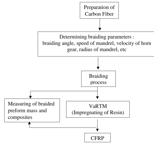
In this thesis, the procedure for the manufacture of braided CFRP composites is described briefly in Figure 2.3.
Figure 2.3 Flow chart for the manufacture of braided CFRP composites Determining braiding parameters :
braiding angle, speed of mandrel, velocity of horn gear, radius of mandrel, etc
Preparation of Carbon Fiber
Braiding process
VaRTM
(Impregnating of Resin) )
CFRP Measuring of braided
preform mass and composites
10
Firstly, preparing carbon fiber to be used in braiding machines, calculating braided parameters based on braiding angle of specimens, conducting the braiding process, measuring the mass of the braided preform and composites, and molding specimens by using VaRTM method for manufacturing the composites with impregnation of epoxy resin on braided preform.
2.2.1. Braiding parameter
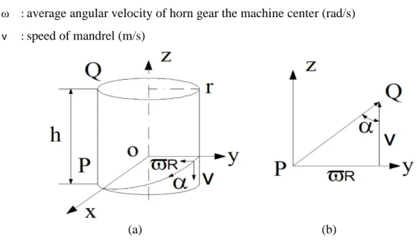
Braiding parameters will affect the final geometry of the braided preform and subsequently the mechanical properties. Figure 2.4 illustrates three primary parameters : speed of the carrier (m/s), speed of the mandrel v (m/s), and the braiding angle (). The secondary parameter is the radius of mandrel r (m), and the distance of the braiding point h (m). An equation relating some of these parameters is given by the simple mathematical relationship:
= 𝑡𝑎𝑛−1(𝜔𝑟𝑣) ... (2-1) Where:
: braiding angle (between threads/yarn and vertical direction) (rad) r : radius of the cylindrical mandrel (m)
: average angular velocity of horn gear the machine center (rad/s)
v : speed of mandrel (m/s)
(a) (b)
Figure 2.4 Schematic of braiding yarn vectors. (a) yarn path on a mandrel. (b) direction vectors.
2.2.2. Braiding process
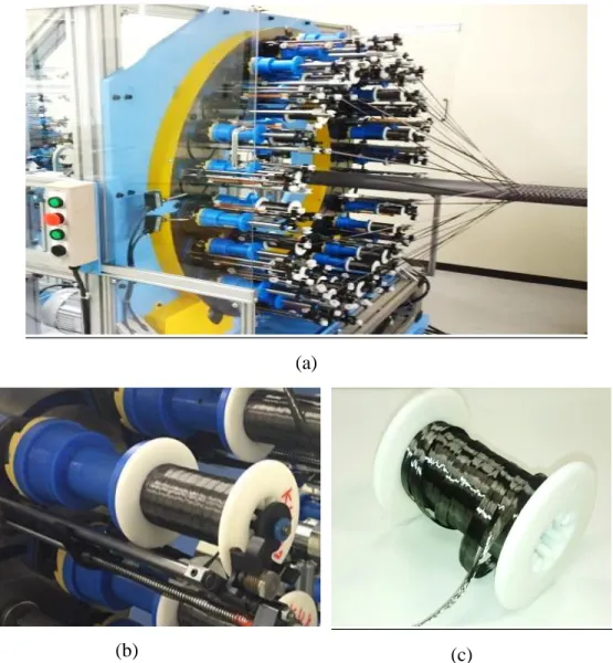
Figure 2.5 (a) shows a circular braiding machine (Kokubun Limited, 40Z048C) used for the braiding process. The braider has 48 bobbin carriers on the front side and 24 Axial yarns
11
(neutral yarn) on the back side. The bobbin carrier is shown in Figure 2.5 (b). At the bobbin carrier, there is also a spring that maintains the tension of the yarn during the braiding process.
Bobbins with carbon fiber are shown in Figure 2.5 (b) where each of the carrier bobbins is fitted with yarn rolled on the bobbin.
(a)
(b) (c)
Figure 2.5 Circular braiding machine for making a braided preform (a) Circular braiding machine with mandrel (b) Detail of bobbin carrier. (c) a bobbin with carbon fiber.
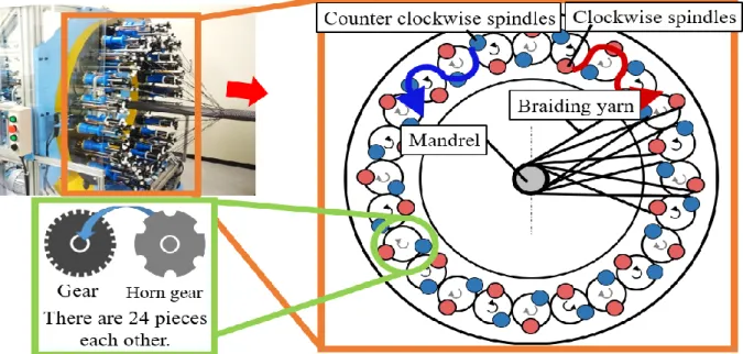
Figure 2.6 shows a mandrel set in the middle of a braiding machine and is surrounded by a bobbin carrier. Inside of the braiding machine, some gear wheels and horns gear are driven by a motor. During the braiding process, half of the carrier bobbins rotate clockwise, and the other half rotates counter-clockwise. When the braiding engine is turned on, the bobbin carrier will
12
rotate around the mandrel and the mandrel will move so that the yarn will be pulled over and intertwine to form a braided structure.
Figure 2.6 Schematic diagram of the circular braiding machine
This circular braiding machine has the advantage of being able to create several types of structures such as biaxial (2x2) and diamond (1x1) by adjusting the number of bobbins, with or without using axial yarn. In addition, the braiding angle can be changed by adjusting the speed of the carrier bobbins and the speed of the mandrel movement. The addition of extra layers is also easy to do by repeating the process over the top of previously braided layers.
The braiding process is done by determining the number of bobbins according to the desired structure (using the whole bobbin or half), adjusting the speed of the bobbins, adjusting the speed of the mandrel, and determining the braiding point. Then, the mandrel is prepared and placed on the robot arm or mandrel carrier. After the mandrel is installed centrally, the yarn is pulled from each bobbin and put it on the braiding point in the mandrel, then the braiding machine is turned on to start the braiding process. If desired multiple layers can be layed down to increase the number of layers or thicknesses of the required braided preform.
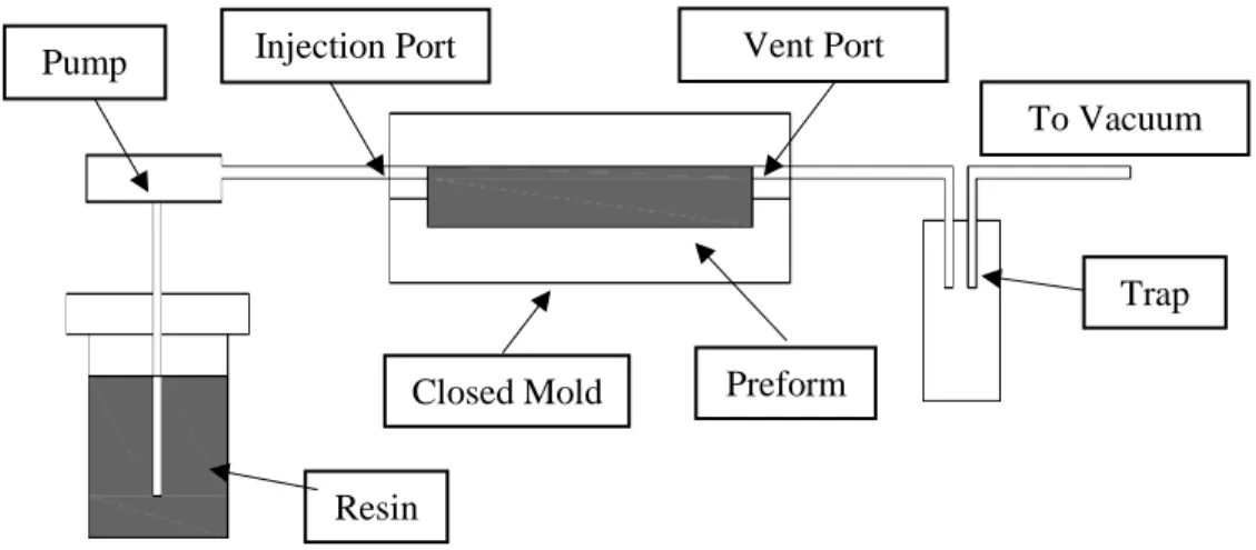
2.2.3. Vacuum assisted resin transfer molding (VaRTM)
Braided composites are generally based on epoxy resin systems due to its high toughness, high strength, low viscosity, good flow rates and low shrinkage [19]. Figure 2.7 shows a schematic of VaRTM process and Figure 2.8 presents a flowchart of the VaRTM process. After
13
the braiding process, the VaRTM system was used for composite molding. Procedures in the VaRTM fabrication process include mold preparation and fabric lay-up, mold sealing and vacuuming, resin preparation at 30 C and impregnation into the mold, and heating the composite at a curing temperature of 60 C for 3 hours. After confirming the composite has set, the sample is released from the mold and the polymer foam removed with limonene liquid.
Figure 2.7 Schematic of VaRTM process
Figure 2.8 Flow chart of molding procedure by using VaRTM Mold preparation and fabric lay-up
Setting to vacuum
Keeping the mold and resin at 30℃
Injection of resin into the mold
Keeping them at 60℃, hold 3 hours
Measuring of products diameter, and setting them to the mold
After the specimens cure, removal of mandrel using limonene Injection Port Vent Port
To Vacuum Pump
Resin
Closed Mold Preform
Trap
14 2.2.4. Determination of fiber volume fraction
One of the most important factors in determining the characteristics of composite materials is the content/percentage of matrix and fiber. Before molding the braided preform, the weight of the cylinder and the carbon fiber weight after braiding process was measured. From this a calculation of CFRP (Vcfrp) volume, fiber volume (Vc), fiber mass (mc) before composite was molded can be made. The geometry of a hollow cylinder is shown in Figure 2.9.
Figure 2.9 Geometric of a hollow cylinder
Estimation of the fiber volume fraction is calculated using the equation below:
volume CFRP, ... 𝑉𝑐𝑓𝑟𝑝= ((𝐷𝑜𝑢𝑡
2 )2𝜋 − (𝐷𝑖𝑛
2 )2𝜋) 𝐿 (2-2) And volume carbon fiber is , 𝑉𝑐 =𝑚𝑐
𝜌𝑐 ... (2-3) So that volume fraction fiber is given as , 𝑓𝑐 = 𝑉𝑐
𝑉𝑐𝑓𝑟𝑝 𝑥 100 % ... (2-2) Where:
Din : Inner Diameter of the specimen after molding (m) Dout : Outer Diameter of the specimen after molding (m) L : Length of specimen (m)
mc : Mass of carbon fiber after braiding process (before molding) (g)
c : Density of carbon fiber (kg/m3)
15 CHAPTER 3
EXPERIMENTAL STUDY ON HOOP STRESS AFFECTING BRAIDED CARBON FIBER REINFORCED PLASTICS SUBJECTED TO INTERNAL PRESSURE
This chapter describes a simple method of analyzing the elastic modulus and the hoop stress on combinations of thin steel cylinders and braided CFRP subjected to internal pressure.
Five configurations of biaxial braided carbon T-700 were produced using a circular braiding machine. Then, a vacuum assisted resin transfer molding (VaRTM) method was used to mold the specimen. Pressure and strain data were obtained from hydraulic experiments used to determine the elastic modulus of CFRP by using simplified methods of combining thin cylinders so that the hoop stress of each cylinder can be evaluated. Thereafter, discussions are provided on: 1) how strain distributions were affected by different braiding angles (45, 60, and 75) and the number of layers (two, three and four layers), and 2) the reduction of the hoop stress on five types of braided CFRP applied to steel cylinders subjected to internal pressure.
3.1. Hoop Stress on The Pressure Vessel Subjected to Internal Pressure
For cylinder wall thicknesses of less than 1/20 of its internal diameter Di (t/Di<1/20 or Di/t>20), then radial stress due to the pressure vessel is quite small compared to the tangential stress so that the radial stress may be neglected, and the pressure vessel is assumed to be a thin pressure vessel [6].
Figure 3.1 Illustration of the stress state in the wall of a thin-walled cylindrical vessel.
16
Under these conditions the tangential stress can be obtained as follows; Let an internal pressure P be applied on the wall of a cylinder of thickness t and diameter D. The force tending to separate two halves of a unit length of the cylinder is PD. This force is resisted by the tangential stress, also called the hoop stress, acting uniformly over the stresses area. We then have PD= 2tt . Figure 3.1 shows a cylinder subjected to internal pressure. The internal pressure generates a force of PA or PDL, or :
𝑃 =𝐹
𝐴 ⇒ 𝐹 = 𝑃. 𝐴 ... (1) 𝑃𝐷𝐿 = 2𝜎ℎ𝐿𝑡 ... (1) 𝜎ℎ = 𝑃𝐷
2𝑡 ... (3-1) Where :
: hoop stress (Mpa) P : Internal pressure (Mpa) d : Diameter of the cylinder (m) t : Cylinder wall thickness (m)
Figure 3.2 Schematic of a cylindrical specimen showing the dual layer construction.
As shown in Figure 3.2, CFRP as the outer layer has an elastic modulus E1 and thickness t1, whereas steel as the inner layer has an elastic modulus E2 and thickness t2. If the contact pressure Pm is defined as an indeterminate constant force, the outer cylinder has internal pressure
17
Pm and the inner ring receives internal pressure P-Pm. Because they are thin rings subjected to internal pressure and D is the diameter of the ring for the displacement conditions (assuming the increase in both diameters is the same, D1 = D2), the elastic modulus and the hoop stress can be calculated:
If there is external pressure Pm and an internal pressure P, the formula is expressed as : 𝜎1 = 𝑃𝑑
2.𝑡1 𝑃𝑚 ...(3-2) 𝜎2 = 𝑃𝑑
2.𝑡2 (𝑃 − 𝑃𝑚) ... (1) The change in diameter due to radial expansion is : 𝛿𝐷1 = 𝐷2
2.𝑡1𝐸1𝑃𝑚... (1) 𝛿𝐷2 = 𝐷2
2.𝑡2𝐸2 (𝑃 − 𝑃𝑚) ... (1) If, 𝛿𝐷1 = 𝛿𝐷2 ... (3-4)
𝐷2
2.𝑡1𝐸1𝑃𝑚 = 𝐷2
2.𝑡2𝐸2 (𝑃 − 𝑃𝑚) ... (1) 𝑃𝑚 = 𝑡1𝐸1
(𝑡1𝐸1+𝑡2𝐸2) 𝑃 ... (3-2) Substituting Pm, the hoop stress of CFRP 1 is:
𝜎1 = 𝐷
2𝑡1𝑃𝑚 = ( 𝐸1
𝐸1.𝑡1+𝐸2.𝑡2)𝑃𝐷
2 ... (3-3) The hoop stress of steel 2 is:
𝜎2 = 𝐷
2𝑡2(𝑃 − 𝑃𝑚) = 𝐸2
𝐸1.𝑡1+𝐸2.𝑡2 𝑃𝐷
2 ... (3-4)
Rearranging equation (2) to solve the modulus CFRP (E1) gives:
𝐸1𝜀1 = 𝐸1
𝐸1.𝑡1+𝐸2.𝑡2 𝑃𝐷
2 ... (2) 𝜀1 = 1
𝐸1.𝑡1+𝐸2.𝑡2 𝑃𝐷
2 ... (2) 𝐸1 =0.5𝑃𝐷−𝜀1𝑡2𝐸2
𝜀1𝑡1 ... (2) 𝐸1 =0.5𝑃𝐷
𝜀1𝑡1 −𝜀1𝑡2𝐸2
𝜀1𝑡1 ... (2) The elastic modulus of CFRP (E1) is given as:
𝐸1 =0.5𝑃𝐷
𝜀1𝑡1 −𝑡2𝐸2
𝑡1 ... (3-5)
18
Equation (3-5) is used to determine the elastic modulus of CFRP on combination thin CFRP-steel cylinder. In order to derive the elastic modulus of composite, combination of CFRP and steel cylinder are considered as a homogenous composite, so the composite has thickness t1+t2 and the hoop stress 3.
(a) (b)
Figure 3.3 Schematic of a cylindrical specimen.
(a). Showing the dual layer construction. (b) Showing composite construction.
Rearranging equation (3-5) to solve the modulus composites (E3) gives:
𝜎3 = 𝑃𝐷
2(𝑡1+𝑡2) ... (3-6) If, 𝜀1 = 𝜀2 = 𝜀3
𝜎3 = 𝐸3. 𝜀3 = 𝐸3. 𝜀1 ... (3-4) 𝐸3. 𝜀1 = 𝑃𝐷
2(𝑡1+𝑡2) ... (3-4) 𝐸3(𝑡1+ 𝑡2) = 𝑃𝐷
2𝜀1 ... (3-7)
Substituting equation (3-7) to equation (3-5) the elastic modulus of the composites (CFRP-steel) E3 is:
𝐸1 =𝐸3(𝑡1+𝑡2)
𝑡1 −𝑡2𝐸2
𝑡1 ... (3-4)
19 𝐸1. 𝑡1 = 𝐸3(𝑡1+ 𝑡2) − 𝐸2. 𝑡2 ... (3-4) 𝐸3 = 𝐸1.𝑡1+ 𝐸2.𝑡2
𝑡1+𝑡2 ... (3-4) 𝐸3 = 𝑡1
𝑡1+𝑡2𝐸1+ 𝑡2
𝑡1+𝑡2𝐸2 ... (3-8) Where:
1 : Hoop stress of CFRP in the composite, (MPa).
2 : Hoop stress of steel in the composite, (MPa).
3 : Hoop stress of the composite, (MPa).
E1 : Elastic modulus of CFRP (GPa).
E2 : Elastic modulus of Steel (GPa).
E3 : Elastic modulus of the composite (GPa).
1 : Strain of CFRP (obtained from experiment, where: 1 = 2 = 3).
2 : Strain of steel.
3 : Strain of the composite.
P : Internal pressure of composite (CFRP-Steel) obtained from experiment (MPa).
t1 : Thickness of CFRP (m).
t2 : Thickness of steel 2 mm or SS t2 (m).
D : Diameter of the cylinder.
3.2. Experimental Procedure
3.2.1. Tested specimen and manufacturing
CFRP was added to the outside of thin steel tubes (SC400, E = 206 GPa with 2 mm wall thickness and 60 mm inner diameter). The CFRP used in this study was made of carbon fiber (Toray Industries, Inc., Torayca 700SC-12000) and epoxy resin (Axson Technologies, Epolam 2031 Resin). Carbon fibers were braided in a biaxial pattern on the steel surface using a circular braiding machine (Kokubun Limited, 40Z048C) with 48 bobbins, as shown in Figure 3.4.
20
Figure 3.4 Fabrication of the braided composite tube specimens using braiding machine.
Five types of braided preforms were applied to the thin steel cylinders. In three types of braided preforms, three layers were applied using different braiding angles (45, 60, and 75);
one type of braided preforms had two layers applied at a 60 braiding angle, and one type of braided preforms had four layers applied at a 60 braiding angle. Table 3.1 shows a list of the number of specimens and strain gauge data used for calculation of the elastic modulus of CFRP.
In this research, for one type of braided preforms (e.g., N3-75) consists of three cylindrical specimens (e.g., N3-75-1, N3-75-2, and N3-75-3). Each cylinder consists of eight strain gauges were attached along the hoop (circumferential) direction, and two strain gauges were attached along the axial (longitudinal) direction. The elastic modulus was analyzed using 24 strain gauges data in hoop direction for one type of braided preforms. However, since some values of the strain gauges were unsuitable or had large fluctuations, values from strain gauges were not used in the calculation.
Bobbin
Mandrel
21
Table 3.1 Summary of specimens and strain gauge data used to evaluate the elastic modulus
Type Sample The number of strain Total of
of Specimens Names gauges Strain Gauges
N2-60-1 8
24
N2-60 N2-60-2 8
N2-60-3 8
N3-45-1 5
16
N3-45 N3-45-2 5
N3-45-3 6
N3-60-1 8
16
N3-60 N3-60-2 -
N3-60-3 8
N3-75-1 8
24
N3-75 N3-75-2 8
N3-75-3 8
N4-60-1 -
16
N4-60 N4-60-2 8
N4-60-3 8
SS t2-1 8
24
SS t2 SS t2-2 8
SS t2-3 8
SS t5-1 8
24
SS t5 SS t5-2 8
SS t5-3 8
Molding process using VaRTM system for braided preforms was conducted after the braiding process, as shown in Figure 3.5. Procedures in the VaRTM fabrication process include mold preparation and fabric lay-up, mold sealing and vacuuming, resin preparation at 30C and impregnation, and keeping samples at 60C for 3 hours. Table 3.2 shows the construction details
22
of the test specimens; it can be shown the fiber volume fraction increases as the braiding angle or the number of layers increases.
Figure 3.5 Description of molding procedure by using VaRTM method
Products for processing Preparing for injection
Wrapping with resin sheets Setting the mold to vacuum
Injection of resin fluid Finishing (remove the mold)
23
Table 3.2 Summary of construction details of the test specimens Name of
specimen
Number of layers
Braiding angle, [°]
Outer diameter, D [mm]
Mass of specimen, [g]
Fiber volume fraction, Wf [%]
N2-60 2 60 65.2 870 33.0
N3-45
3
45 65.7 900 43.6
N3-60 60 66.2 960 48.6
N3-75 75 67.9 1020 51.7
N4-60 4 60 66.8 960 50.2
SS t2 64.0 850
SS t5 70.0 2230
3.2.2. Pressurized oil testing method
Figure 3.6 shows a system of the hydraulic pressure test. The schematic of the entire test equipment is provided in Figure 3.6(a). Figure 3.6(b) shows an image of output strain data and internal pressure were simultaneously recorded using camera. The specimen (length = 280 mm) was placed on a high-pressure resistant jig and connected to a hydraulic pump oil hose outlet is indicated in Figure 3.6(c).
During the experiment, the pressure applied by the hydraulic pump was measured by a mechanical pressure gauge. The strain values was separately read by the data logger and displayed using the wave logger software. Instead of the data logger, we also used a camera to record the internal pressure changes in pressure gauges and strains data from data logger on a personal computer simultaneously.
Strain gauges were placed along the centers and edges of specimens in order to measure the distribution of the strains. After the strain gauges were connected to the computer and calibrated, a hydraulic pump (Hanmi Hydraulic Co., Ltd., Model: HML – 1700N) was used to inject oil into the empty test specimens to increase the pressure inside the pipe.
24 (a)
(b)
(c)
Figure 3.6 Details of the hydraulic pressure test. (a) Schematic diagram of the measurement system. (b) The image of output strain and internal pressure data recorded by camera.
(c) Test piece setup.
Oil injection
Data logger
Strain Gauge
Pressure indicator
Hydraulic jack
Video camera
Camera sight Specimen
Send strain-time data
25
The experiment continued until a large fluctuation in the strain value or visible failure of the test specimen was observed. At each end of the inner wall of the test cylinder and jig, there are two seals. Because the viscosity of oil is greater than that of air, as the cylinders are filled the air will be pushed out and escape through these seals. To accommodate increases in pressure during the experiment, these seals serve as safety valves, to be sacrificially damaged at high pressures in order to prevent explosive releases of oil or damage to the jigs and hydraulic pumps.
3.3. Determination of Elastic Modulus
The data from the eight strain gauges in the hoop direction of the specimen, and hoop stress were plotted in a hoop stress-strain curve to determine the gradient in the linear region of the curve. The average modulus of CFRP was analyzed from the eight hoop stress-strain curves for each specimen (some specimens have less than eight curves). The two strain gauges in the axial direction were not used for thin cylindrical calculations. E2 is the elastic modulus of steel SC400, and the theoretical steel modulus is 206 GPa, this value agrees with the average elastic modulus of steel when calculated using the hoop stress-strain curve from experimental data.
3.3.1. Elastic modulus of steel
Determination of the elastic modulus of steel E2 is conducted using a steel cylinder without CFRP. First, calculating the value of the hoop stress of steel s at each pressure value Ps, then, plotting the stress-strain hoop curve (s-s). From this curve , the slope is determined from which the elastic modulus of the steel E2 is known. For the steel cylinder specimen without CFRP the elastic modulus of steel can be calculated using this equation :
𝐸2 = 𝜎𝑠
𝜀𝑠 ... (3-9) If, 𝜎𝑠 =0.5𝑃𝑠𝐷
𝑡2 ... (3-10) Where:
E2 : Elastic modulus of Steel (GPa).
Ps : Internal pressure of steel (SS t2) obtained from experiment (Mpa) 𝜀𝑠 : Strain of steel (SS t2) obtained from experiment
𝜎𝑠 : Hoop Stress of steel (SS t2) obtained from experiment
26 (a)
(b)
Figure 3.7 Determination of elastic modulus of steel E2 on test specimen : SS t2-1-7 (a) Relationship between pressure Ps and strain s, (b) Relationship between hoop stress and
strain (s-s).
R² = 0.9963
0.E+00 5.E+06 1.E+07 2.E+07 2.E+07 3.E+07 3.E+07 4.E+07 4.E+07
0 0.001 0.002 0.003 0.004 0.005 0.006 0.007 0.008
Pressure of Steel, Ps(Pa)
Strain, s
SS 2t Sample 1- strain gauges 7
Steel
R² = 0.9963
0.E+00 1.E+08 2.E+08 3.E+08 4.E+08 5.E+08 6.E+08
0 0.005 0.01 0.015 0.02 0.025
Hoop Stress, s(Pa)
Strain, s
SS 2t Sample 1- strain gauges 7
Elastic Region
Plastic Region
Gradient E2of curve(s-s)
27
Figure 3.7, shows the determination of the gradient of the stress-strain curve (s-s) of SS t2 (steel with 2 mm thickness). Figure 3.7 (a) shows the relationship between pressure Ps and strain value s of 2 mm steel or SS t2 (specimen 1-strain gauges number 7). Hoop stress values s were calculated from the pressure of steel Ps (using equation 3-6), then the values of the hoop stress s
were plotted versus strain value s which was obtained by experiment, as shown in Figure 3.7 (b).
From the gradient on the graph the value of the elastic modulus of steel Es (St 2 mm-1-7) was found to be 205.51 GPa. The elastic modulus of all specimens was determined in the same way using eight strain gauges to obtain the average modulus of SS t2, as shown in Table 3.3.
Table 3.3 Elastic modulus E2 results for ST 2 mm and Theory [20]
Strain gauge Number
Elastic Modulus of the specimen (GPa)
Average E2
From experiment (GPa)
Average E2
From Theory (GPa)
1 2 3
1 207.21 218.79 184.44
2 186.18 198.46 211.82
3 211.85 178.95 215.76
4 192.90 219.93 218.79
5 208.93 210.52 196.12
6 203.03 187.10 202.20
7 205.51 199.03 223.30
8 217.74 218.83 219.07
Average of E2 204.17 203.95 208.94 205.69 206
3.3.2. Elastic modulus of CFRP
The elastic modulus of CFRP (E1) was calculated using simplified methods for combining thin cylinders using equation (3-5). Equation (3-5) consists of some constant variables (E2, t1, t2, and D). Pressure P and strain 1 are variable and were obtained from experiment using CFRP- Steel specimens. Determination of the elastic modulus used the pressure, P, and strain, 1, values in the elastic or linear region of the curve.
28 (a)
(b)
Figure 3.8 Relationship between Stress and Strain for test specimen: N-75-2-1. (a) Relationship between pressure P and strain 1, (b) Relationship between hoop stress and strain (3-1).
R² = 0.995
0.00E+00 1.00E+07 2.00E+07 3.00E+07 4.00E+07 5.00E+07 6.00E+07 7.00E+07
0 0.002 0.004 0.006 0.008
Pressure, P(Pa)
Strain, 1
N3-75-2 Sample 2- strain gauge 1
CFRP applied to Steel N3-75-2, Strain 1
Elastic Region
0.00E+00 1.00E+08 2.00E+08 3.00E+08 4.00E+08 5.00E+08 6.00E+08
0 0.001 0.002 0.003 0.004 0.005 0.006
Hoop Stress, 3(Pa)
1(Strain)
N3-75-2 Sample 2- strain gauge 1
Gradient E3 of curve (3-1) of CFRP applied to steel
29
Figure 3.8 (a) shows the curve of the relationship between the pressure (P) and the strain (1). It shows the elastic region on the curve. Where, in this linear region, pressure P and the strain 1 values are used for calculation in equation (3-5).
Figure 3.8 (b) shows the curve of the relationship between the hoop stress 3 and the strain 1.. The hoop stress 3 is calculated using equation (3-6). The linear region of hoop stress
3 and the strain 1 curve is shown. After determining the elastic modulus of CFRP E1, the elastic modulus of composites E3 can be calculated using equation (3-8).
The elastic modulus of CFRP E1 of all specimens was determined using the same procedure with eight strain gauges to obtain the average modulus of all specimens for each type of braided preform, as shown in Table 3.4.
Table 3.4 Elastic modulus results for CFRP (E1) Type Sample Elastic Modulus
of CFRP E1
Average E1
of CFRP
Deviation Standard of E1
Elastic Modulus of Composites E3
of Specimens Names (GPa) (GPa) (GPa)
N2-60-1 65.35
58 44.60
N2-60 N2-60-2 52.93 172
N2-60-3 58.85 N3-45-1 60.59
61 37.33
N3-45 N3-45-2 50.81 163
N3-45-3 71.77 N3-60-1 74.91
72 36.40
N3-60 N3-60-2 - 158
N3-60-3 69.19 N3-75-1 131.36
122 27.50
N3-75 N3-75-2 137.18 165
N3-75-3 98.71
N4-60-1 -
93 29.19
N4-60 N4-60-2 93.87 164
N4-60-3 91.84 SS t2-1 204.17
206 12.90
SS t2 SS t2-2 203.95 -
SS t2-3 208.94
30 3.4. Determination of Hoop Stress
In this study, the hoop stress was calculated from the elastic modulus value by using the thin pressure vessel equation. The elastic modulus value used was from the experimental data.
After the elastic modulus of CFRP (E1) and Steel (E2) were determined, then the hoop stress was determined by the following equations :
1. Hoop stress of CFRP 𝜎1 = 𝐸1
𝑡1𝐸1+𝑡2𝐸2 𝑃𝐷
2 ...(3-11) (2) 2. Hoop stress of Steel
𝜎2 = 𝐸1
𝑡1𝐸1+𝑡2𝐸2 𝑃𝐷
2 ...(3-12) (3) 3. Hoop stress of the composite
𝜎𝑢𝑛𝑖𝑡= 𝐷
2(𝑡1+𝑡2)𝑃 ...(3-13) (3) (2) 4. Hoop stress of SS t2 and SS t5
𝜎 = 𝐷
2𝑡𝑃 ...(3-14) (3) (2) Where : E1 and E2 was obtained from the experimental data
3.5. Results and Discussion
3.5.1. Effect of the braiding structure on the distribution of strains and the elastic modulus of CFRP
Figure 3.9 shows the relationship between applied internal pressure and average strain.
The strain value variation in the specimen due to high internal pressure produces the different gradients on the pressure-strain curve obtained from the strain gauges on the specimen; as a result, the specimens show different elastic modulus. Other studies have also found that composites have a highly sensitive mechanical response to the distinct variations that impact the distribution of strains [8]; they found that increased pressure causes micro mechanism failures in multiple regions, and that damage sequences do not necessarily occur at the same time [9,10].
31
Figure 3.9 Relationship between applied internal pressure and average strain.
The experiment results of strain values of CFRP-Steel 1 on the specimen N2-60-1 at each strain gauge in circumferential direction (number 1 up to 8), and the internal pressure of CFRP- Steel P using, as shown in Figure 3.10.
Figure 3.10 Relationship between between applied internal pressure (P) and strain () 0
10 20 30 40 50 60 70
0 0.002 0.004 0.006 0.008
P(MPa)
Mean Strain
N2-60 N3-45 N3-60 N4-60 N3-75 SS t2 SS t5
0.00E+00 1.00E+01 2.00E+01 3.00E+01 4.00E+01 5.00E+01
0 3E-09 6E-09 9E-09 1.2E-08 1.5E-08
P(MPa)
Strain, 1 N2-60-1
32
Figure 3.11 and 3.12 indicated the Scanning Electron Microscope (SEM) image (25 x) of surface fiber break and damage (crack) was confirmed on the specimens respectively. The destruction of CFRP occurs along the direction of fiber orientation and the specimen.
a.N2-60 b. N3-45
c. N3-60 d. N4-60
Figure 3.11 SEM image (25X) Fiber break on the specimen due to internal pressure
a.N2-60 b.N3-45
c.N3-60 d.N4-60
Figure 3.12 SEM image (25X) matrix cracks on along the specimen because the internal pressure
0.2 mm /div 0.2 mm /div
0.2 mm /div
0.2 mm /div 0.2 mm /div
0.2 mm /div
0.2 mm /div 0.2 mm /div
33
As the braiding angle increases, the thickness of the CFRP increases and the direction of the fibers becomes closer to the hoop stress direction; on the other hand, the fiber volume fraction increases when the braiding angle is large, so that many fibers can distribute the load [1].
Figure 3.13 presents the test specimens after being subjected to internal pressure. As shown in Figure 3.13(b) the braiding angle was measured from the long axis of the tube. In Figure 3.13(g), 3.13(h), and 3.13(i), depict the deformation on the specimen, which is indicated by the gap between specimen and ruler line. At low braiding angles (e.g., ~ 45), larger deformations of the specimen occur than high braiding angle (e.g., ~ 60 and 75). This increases the difference between the strain value and the elastic modulus when the specimen is braided with CRFP at 45; because of the lower braiding angle, the CFRP has less thickness and the fiber is not close to the hoop stress direction. On the contrary, at a higher braiding angle (e.g., ~ 75), in which the thickness of the CFRP increases and the fiber more closely follows the hoop direction, the specimen tends to be stable and able to resist the internal pressure; in other words, the CFRP has greater ability to withstand the internal pressure. As a result, the elastic modulus deviation value decreases as the braiding angle increases. The relationship between the elastic modulus of the specimens and the variation of the braiding angle is illustrated in Figure 3.14(a). It was calculated that specimens braided at 75 had the highest elastic modulus value, followed by those braided at 60 and at 45.
With regard to the difference in the number of layers for 60 angle braided specimens, as the thickness and fiber volume fraction of the specimen increase, it is expected that, the elastic modulus value increases [11]. The fracture of the test specimens after the hydraulic pressure test are shown in Figure 3.13(j), 3.13(k), and 3.13(l). As shown in Figure 3.13(j), the results of the pressure test indicate that, compared to specimens with three or four layers, CFRP with two layers (N2-60) had greater damage, with fiber breaks occurring due to a large local deformation.
In terms of specimens with three or four layers, as shown In Figure 3.13(k) and 3.12(l), the local deformations decreased, although a crack occurred in the matrix along the specimen. The relationship between the elastic modulus of the specimens and the variation of the number of layers is shown in Figure 3.14(b). The average modulus value increases as the number of layers increases. In other words, the addition of layers can increase the elastic modulus, owing to the increased thickness of the CFRP and fiber volume fraction. The same trend also occurs in cases where the elastic modulus deviation decreases when the number of layers is increased from two