INVITED PAPER Special Section on Visible Light Communications in Conjunction with Topics of ICEVLC 2015
Image Sensors Meet LEDs
Koji KAMAKURA†a),Member
SUMMARY A new class of visible light communication (VLC) sys- tems, namely image sensor (IS) based VLC systems, has emerged. An IS consists of a two-dimensional (2D) array of photodetectors (PDs), and then VLC systems with an IS receiver are capable of exploiting the spa- tial dimensions invoked for transmitting information. This paper aims for providing a brief survey of topics related to the IS-based VLC, and then provides a matrix representation of how to map a series of one dimensional (1D) symbols onto a set of 2D symbols for efficiently exploit the associate grade of freedom offered by 2D VLC systems. As an example, the matrix representation is applied to the symbol mapping oflayered space-time cod- ing (L-STC), which is presented to enlarge the coverage of IS-based VLC that is limited by pixel resolution of ISs.
key words: image sensor, LED, visible light communication (VLC), optical wireless communication (OWC), two-dimensional communication, space- time coding (STC)
1. Introduction
The rapid increase in the usage of LEDs has lead to the ad- vent in recent years of visible light communication (VLC).
VLC is emerging as a solution to overcome the crowded ra- tio spectrum for wireless communication systems. In VLC, information is transmitted by modulating the intensity of an optical light source operating in visible range of the spec- trum at a rate much faster than the response time of the hu- man eye. LEDs are the most suitable light source for VLC due to their capability of high switching rate.
Initial studies on VLC using LED lighting were done in[1], where data can be provided from a local aggrega- tion point to the luminaries via existing infrastructure like traffic lights and a single photodiode (PD) was used as a re- ceiver. Nowadays, thanks to low-cost complementary metal oxide semiconductors (CMOSs) that consume less power while delivering high performance and advanced features, image sensors (ISs), which are an two-dimensional (2D) ar- ray of PDs, have been embedded in today’s low-end cell phones and tablet devices. Therefore, in order to receive the modulated LED lights, there are two types of receiver: PDs [2]–[5]and ISs[6]–[9].
Single-element PD receivers have an advantage of con- verting optical signals at very high rates, but they suffer from large interference and background light noise. This results in very low SNRs and thus short communication ranges such
Manuscript received September 2, 2016.
Manuscript revised November 14, 2016.
Manuscript publicized December 14, 2016.
†The author is with Department of Computer Science, Chiba Institute of Technology, Narashino-shi, 275-8588 Japan.
a) E-mail: [email protected] DOI: 10.1587/transcom.2016LCI0001
as offices and rooms. To increase the data rate of the single- transmitter single-receiver system using the same amount of signal power, multiple-input multiple-output (MIMO) are investigated, where the parallel data streams can be trans- mitted over either different spatial locations[4]or different colors of light[5]. In[5], 8 Gbps is reported to be achieved over a 1-meter indoor link with an red-blue-green-yellow LED and R/G/B/Y filters. The main drawbacks of this ap- proach are potentially large size and high cost of the multi- ple receiving elements.
On the other hand, IS receivers consist of a 2D array of PDs, each of which converts incident light to an electrical signal and has it as a digitized value individually. Therefore, their outputs are essentially discrete. Furthermore, they are compact, which constitute a camera structure. The camera lens provides a different narrow field of view (FOV) for each pixel. This creates a large number of highly directional re- ceiving pixels, which allows a degree of flexibility of selec- tively combining pixels that receive a strong signal from the light emitting elements that can not be attained by the type of single-element PD receivers. The tradeoff in the IS re- ceiver, however, is a limited sampling rate of the camera re- ceiver. The frame rate ranges from tens to hundreds frames per second for low-end cameras and a million frames per second for high-end models. Yet, it is reported in[10]that with a customized CMOS IS, a 54 Mbps is achieved, which strikes a good tradeoff between high-speed optical-signal re- ception and LED-transmitter detection.
This paper focuses on IS-based VLC. IS-based VLC was initially demonstrated in[11]with high-speed camera for intelligent transport systems (ITS), where LEDs are used as road side unit to transmit location or safe driving informa- tion from traffic lights to vehicles, which is now extended to communications of vehicle to infrastructure (V2I)[10]and vehicle to vehicle (V2V)[12]. It is also found in[13]that V2V communication with IS receiver is investigated for in- frared (IR), instead of visible light.
Meanwhile, low-end camera-equipped cell phones and tablet devices can shoot videos at a frame rate around 20 fps, thanks to the rolling shutter. This shutter operation is inves- tigated to receive data at a rate that far exceeds the frame rate of the camera[14]–[17].
VLC research was started off in 2003 by the Visible Light Communications Consortium (VLCC) [18], which is the successor of Visible Light Communications Asso- ciation (VLCA), receiving increasing interest worldwide.
They term it as image sensor communication (ISC). Con- Copyright © 2017 The Institute of Electronics, Information and Communication Engineers
sequently, the visible light spectrum is now in a state of ac- tion after the IEEE standardization of VLC technology in 2011[19]. In the Task Group (TG7r1), ISC, which is also referred to as optical camera communications (OCC), is dis- cussed as a part of optical wireless communication (OWC) that uses the camera sensor as a receiver.
The aims of this paper are two folds. First, it aims at providing a brief survey of IS-based VLC systems, while avoiding duplication of efforts done in [12], [20], [21], which give excellent introductions to IS-based VLC. Sec- tion 2 gives a brief explanation of IS used for the receiver, and modulation with lighting constraints is mentioned in Sect. 3. Since VLC and OWC have in common such as conventional digital modulation techniques, the interested reader will also be provided with references[3],[22],[23]
for a more in-depth study of the techniques. Secondly, this paper aims for providing a matrix representation of how to map one-dimension (1D) symbols onto a 2D array of trans- mitting LEDs for IS-based VLC, which includes the area termed ISC, CamCom, and OCC. Section 4.1 mentions in- trinsic limits in IS-based VLC systems, and then Sect. 4.2 describes the bit-to-symbol mapping of 1D signals to 2D ones for the 2D system, with a matrix representation. The matrix representation can be easily adapted to make efficient use of spatial dimensions of rows and columns of the trans- mitting device array as additional dimensions invoked for transmitting information. This matrix expression is applied to a modulation for IS-based VLC, which is presented as layered space-time coding (L-STC)in [24]. More specif- ically, with the matrix expression, the symbol mapping of three-layered STC is rewritten so that readers can easily un- derstand how it is done for expanding the coverage of IS- based VLC through L-STC in Sect. 4.3. Finally, conclusions are presented in Sect. 5.
2. IS-based VLC Components
2.1 CMOS Image Sensor
A CMOS IS has an imaging area, which consists of an array of pixels, vertical and horizontal access circuitry, and read- out circuitry, as shown in Fig. 1. The imaging area is a 2D array of pixels, each of which has a PD and some transistors inside. CMOS chips have transistors at each pixel to move the charge through lines. This offers flexibility because each pixel is treated individually, unlike CCD[25],[26]. Access circuitry is used to access a pixel and read the signal value in the pixel. For this purpose, a shift resistor is used, and a decoder is used to access pixels randomly. A readout circuit is a 1D array of switches and a sample-and-hold circuit.
2.1.1 Sensitivity
In terms of sensitivity of IS inside a camera, two parameters are very important: quantum efficiency and read noise.
Quantum efficiency is a measure of how efficiently the IS converts light (photons) to charge (electrons). The
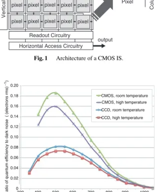
Fig. 1 Architecture of a CMOS IS.
Fig. 2 ηQ/ND versus wavelength at the frame rate of 30 fps (by Adimec).
more electrons into a pixel during the integration period, the higher the output level of the IS, so the more sensitive the IS is for that specific wavelength of the light.
Read noise is the random noise generated within the charge-to-voltage conversion amplifier when reading out the charge. It has the noise level equivalent to the output of the IS when the IS is in the dark place during zero inte- gration time. The lower the read noise level is, the lower the minimum number of signal electrons is that can be de- tected. Therefore, lower read noise results in a more sensi- tive IS. Recent CMOS technology offers an extremely low read noise that are close to high performance CCD ISs[27].
More precisely, the noise level at the output of the IS is not only determined by the read noise, but the dark current of a pixel also contributes to the dark noise. The dark current is dependent on the quality of the IS, and also very depen- dent on the temperature and the integration time. At higher temperatures the dark current increases rapidly and then the dark noise will be larger than the read noise. For temper- ature, the dark noise should be considered rather than the read noise[27].
With the ratio of quantum efficiencyηQto dark noise ND, as the ratio increases, the IS is more sensitive at a par- ticular wavelength. Fig. 2 shows the ratio for recent CMOS
and CCD ISs at two temperatures: room temperature and a higher temperature. The curves show that the CMOS IS is more sensitive than the CCD one at all wavelengths. We can also see that the ISs perform worse at higher temperatures than at room temperature. The sensitivity of the camera in lower light conditions is necessary for VLC scenarios. The ratio gives the overall sensitivity of the IS, or the minimum amount of light detectable. Nowadays, CMOS ISs have a higher efficiency than CCD ones at all wavelengths.
2.1.2 Shutter Operations
In digital cameras, the luminance value generated by the IS depends on the voltage signal, which is induced by elec- tron charge. The electron charge is related to the amount of light that falls on the photosensitive area, in terms of dura- tion. They therefore require some form of shutter to control exposure time. This is generally achieved by incorporating either an external mechanical shutter in front of the IS or an on-chip electronic shutter.
In the point of view for VLC applications, we focus on two types of electronic shutter: global shutter and rolling shutter.
Global shuttercontrols incoming light to all pixels si- multaneously. At any given point in time, all pixels of a frame (image) are therefore either equally closed or equally open. All pixels are reset simultaneously, and integration of all pixels begin at the same time. Therefore, data integrated over the same time duration is output from all pixels, which is desirable for VLC receivers.
Rolling shutteris an readout architecture, in which, not all portions of the image start and stop receiving light at the same time. In order to maintain high fill factor and read out speed, most CMOS ISs are equipped with column- parallel readout circuits, which simultaneously read all pix- els in a row into a line memory. The readout proceeds row- by-row, sequentially from top to bottom, as shown in Fig. 3.
This is called “rolling shutter” operation.
High resolution image requires the increase in the num- ber of PDs, but this significantly reduces the frame rate, which is the number of frames per second (fps) that can be captured by the IS. Thanks to the rolling shutter, recent mo- bile devices have ISs to capture videos at a certain frame rate. Even the least expensive smartphones nowadays are equipped with high-resolution CMOS IS inside cameras, they can shoot full HD videos at 30 or even 60 fps. How- ever, this means that direct use of the IS for VLC receivers can provide very low data rate.
Even though the advance in CMOS technology has im- proved the resolutions of ISs to very high levels, it is still difficult to have high-frame-rate camera with such high- resolutions at low cost. Therefore, to use the most of the rolling shutter mechanism of CMOS ISs for receive mul- tiple bits modulated at a high frequency within one frame, an approach is presented[9], which achieves a few kbps of throughput with the rolling shutter process of camera sensor operating at 20 fps. When capturing an image, most CMOS
Fig. 3 Rolling shutter effect observed when capturing the LED blinking at a rate faster than the frame rate.
ISs expose one or more columns of pixels, but read out only one column at a time, sweeping across the image at a fixed scan rate to create a rolling shutter, as shown in Fig. 3. First, an LED is in ON which results in higher intensity output for pixels of the first row. At the next time instance, when the LED changes its state to OFF, the IS reads it out as low in- tensity output for pixels of the second row. After all the rows are scanned, the resultant image can be converted to binary data. This effect is neither visible to the naked eye, nor in a photograph that uses an auto-exposure setting. This idea is applied to for vehicular communication[28], positioning [29], and encryption[30].
3. Modulation under Lighting Constraints
3.1 Dimming
Different levels of illuminance are required when perform- ing different types of activities[31]. For example, an illumi- nance in the range of 30–100 lux is often said to be enough for simple visual tasks performed in most public places, while office or residential applications require higher level of illuminance in the range of 100–1000 lux. The luminance is measured in lux (lux = lm/m2), which is the luminous flux incident per unit area. The lm (lumen) is the unit of lu- minous flux, which represents the light power of sources as perceived by human eye. It is defined as a monochro- matic light source emitting an optical power of 1/683 watt at 555 nm has a luminous flux of one lumen. The light of a full moon provides an illumination of about one lux, and on a sunny day outdoors, the illumination would be about 100,000 lux.
With the advancements in LED driver circuits, it has become possible to dim an LED to an arbitrary level de- pending on the application requirement to save energy. If an LED can be dimmed to an arbitrary level, it is also neces- sary to understand its impact on the human perceived light.
It was first shown in[32]that the relation between the mea- sured light and the perceived light is nonlinear. The per- ceived light can be calculated from the measured light as [32],[33]
Perceived light(%)=100×
√Measured light(%)
100 . (1)
For example, at full brightness, the measured light in a space
is 60 foot-candles (fcd). Eq. (1) indicates that a lamp that is dimmed 1% (0.6 fcd) of its measured light is perceived to be 10% dimmed by the human eye. This is important in terms of VLC because a user may choose an arbitrary level of dimming depending on the application or desired energy savings, but the communication should not be affected by the dimming; i.e., the data should be modulated in such a way that any desired level of dimming is supported.
3.2 Flicker Constraint
An additional constraint on any VLC modulation is that it should not result in human perceivable fluctuations in the brightness of the light. Since the flicker has little impact on human eye perception when light pulses blink at 200 Hz or higher frequency[19], the average intensity is constrained.
This constraint relates the intensity and the signal level it- self. This new constraint, which is referred to as the dim- ming target, introduces a new domain of system design which has rarely been considered in existing communica- tion media.
3.3 Modulation with Lighting Constrains
A typical non-return-to-zero (NRZ) on-off keying (OOK) has 50% average intensity for equiprobable binary symbols.
For the lighting constraint of 75% dimming, it simply shifts the OFF symbol level from 0% intensity level to 50%, which is referred to as analog dimming. However, a non-linear characteristic of LEDs poses some difficulties and further the reduced level margin faces on difficulties, and the re- duced margin between the two intensity levels degrades the signal detection performance.
One solution to mitigate long runs of 1s and 0s as on and off states is to compensate the intensity difference in time. For a general data transmission rate with equiproba- ble binary symbols, the same duration of dummy ON trans- mission is appended to meet the target 75% dimming. If the target is below 50%, a dummy OFF symbol interval is appended to resolve the difference. The dummy transmis- sion is presented in the IEEE standard[32]. On the other hand, pulse width modulation (PWM) is used for providing a marginal rate enhancement[34]. PWM can be also super- posed with OOK and pulse position modulation (PPM) for dimming support[35].
Another solution is to use run length limited (RLL) codes. RLL codes ensure that the output symbols have bal- anced repetition of 0 s and 1s. Examples of commonly used RLL codes include Manchester, 4B6B, and 8B10B coding.
In Manchester coding, a 0 is replaced with a “down” transi- tion (one-to-zero) and a 1 is replaced with an “up” transition (zero-to-one). 4B6B coding maps a 4-bit symbol to a 6- bit symbol that has balanced repetition. Similarly, 8B10B maps an 8-bit symbol to a 10-bit symbol. Since the Manch- ester coding has the highest in the number of additional bits added, it can be a suitable choice for low data rate services that require better DC balancing. On the other hand, 8B10B
reduces the number of additional bits added, but it performs poorly in terms of the DC balancing.
Furthermore, a dimming technique in VLC is inverse source coding [36], which uses the ratio of 1s and 0s for satisfying the required dimming target. For example, if the dimming ratio is 70%, then 70% of the output bits must be 1s. The encoding scheme increases the number of transmit- ted data bits to achieve the dimming ratio. Huffman coding is generally used as the encoding scheme, where only an approximation to the required dimming ratio is achieved.
4. Two-Dimensional Systems
4.1 Four Distortions
Most of the luminaries typically contain multiple LEDs to provide sufficient illumination. When these multiple LEDs can be treated as an array of multiple transmitters that works as a 2D transmitter. VLC systems between such an transmit- ter array and the corresponding IS receiver constitutes a 2D system. The 2D system has attractive mapping options due to additional dimensions invoked for transmitting data.
The IS inside cameras can provide a wide receiving FOV that allows for node mobility without the need to re- align the receiver. Yet, because of the camera design, each pixel has a very narrow FOV, allowing high gain commu- nication. The camera lens creates the effect of each pixel being angled to a slightly different part of the scene, so that the combination of all LEDs of the array generates an image with a wide FOV.
The 2D system provides a new domain to transmitting data, but exhibit four main types of distortions below.
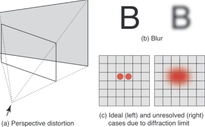
1) Perspective distortion is a common phenomenon in our daily life. When we take a look at a rectangular array from a certain angle, the image on the plane is like a trape- zoid, as shown in Fig. 4(a). In the typical case of a projector sitting on a table and looking upwards to the wall screen, the image is larger at the top than on the bottom. Consequently, some LEDs on an array expand at the IS plane inside cam- era, while others shrink[37].
2) Blurringoccurs when the camera moves while cap-
Fig. 4 Examples of distortions considered in the imaging system.
turing an image or a lack of focus can introduce blur in the image, which causes the pixels to blend together, as in Fig. 4(b). An array-camera communication system must be able to deal with such blending and still successfully recover the transmitted bits. In the frequency domain, blur can be considered a low-pass filter where high frequency attenuates much more than the low frequency.
3) Ambient Lightis a source of noise for array-camera links because it changes the luminance of the received pix- els. This can cause errors in the information bits decoded from the pixels. In frequency domain, it can be considered the DC component.
4) Diffraction limit determines the angular resolution, thus limiting the pixel resolution in any imaging system.
Light is collected by a lens which limits the spatial extent over which it can be received. If the wavelength of light isλ and the diameter of the lens’ aperture is D, the angu- lar resolution set by the diffraction limit is θ = 1.22λ/D radians [24]. For example, in an imaging system operat- ing atλ=630 nm with D=2 mm, the angular resolution is about3.84×10−4radians (79.3arc-seconds), corresponding to a spatial resolution of 76.9 mm at a distance of 200 m.
This means that IS receivers cannot discern two points at the distance of 200 m when they are separated from each other by 76.9 mm or less. In such a diffraction-limited region, intensity-modulated signals transmitted from two 20 mm-away LEDs disperse and become unresolved LED pair, as shown in Fig. 4(c), thus impossible to demodulate from them.
In real world scenarios, we further face i) camera mo- tion, ii) illumination variation, and iii) background dis- tracters such as other vehicles on the road [38]. Camera motion is inherently present in the visual MIMO communi- cations system because the camera at the receiver and LED transmitters are on different mobile nodes. Consequently, the geometry of the image formation process varies, i.e., the position and orientation of the camera center with respect to the scene varies. As the camera moves further, the object of interest appears to become smaller. Because of this per- spective projection, the LED array undergoes arbitrary scal- ing, and the standard communication approach of template matching with matched filters or with correlation-based de- tectors might be insufficient. The computer vision literature has numerous methods for achieving scale invariance in ob- ject recognition, which often require heavy processing.
4.2 Matrix Expression of Transmitter Design of 2D Sys- tems
In order to efficiently exploit the spatial degree of freedom of the 2D system, this section gives an matrix expression.
Consider a 2D communication system, composed of an LED array transmitter, an optical channel, and an IS re- ceiver, as shown in Fig. 5. We assume an LED array as the 2D transmitting device here, but it can be a pixelated array such as computer display, screen, or digital signage [7],[37],[41]. In general, an input to the 2D system can be
Fig. 5 An overview of a 2D optical wireless communication system be- tween an LED array and an IS.
a one-dimension stream of complex symbols. The output of the 2D mapper inside the 2D system will be a set of unipo- lar signals (i.e., real but non-negative), and then are trans- mitted as intensity signals from the LED array. Such signals pass through the optical channel into the IS receiver inside cameras, followed by the 2D demapper with the receiver’s output data stream.
Let {s} be a stream of complex symbols into the 2D system. The function of the 2D mapper is to convert {s} into a series of 2D symbols. WhenN1N2symbols from{s} are fed to the mapper, it outputs the complex symbol matrix S=SI +j·SQof size N1×N2. Sshould be converted to a unipolar symbol matrixXof size (M1N1)×(M2N2), which is an expansion by M1 ×M2 inside the 2D mapper. The complex inputS and the unipolar outputX are considered in the spatial domain.
The process of the 2D mapper is detailed. Let AI and AQbe two matrices, each of which has size M1×M2. AI
andAQhave orthonormality constraints, given by
AI•AI =AQ•AQ =1, AI•AQ=0, (2) where•denotes the Frobenius inner product. The Frobenius inner product of two real matrices is a scalar, defined as
A•B=trace( ABT)
=trace( B AT)
. (3)
The conditions of Eq. (2) do not uniquely determineAI
andAQ, leaving enough degrees of freedom while specify- ing them. We can use this freedom to satisfy a diverse range of practical requirements and to design a meritorious trans- mission scheme.
To take the benefits of spatial domain consisting of (N1M1) ×(N2M2) transmitting devices, the mapper gen- erates symbols to modulate the individual transmitting de- vices separately. Through the expansion process, the two real bipolar matricesSI andSQ are expanded intoGI and GQof size (M1N1)×(M2N2) by
GI =SI ⊗E1,1, GQ =SQ⊗E1,1, (4) where E1,1 is an M1 ×M2 matrix with all zero elements except a single one at the index (1,1), and ⊗ is the ten- sor multiplication operation of the two matrices. If P is an m×nmatrix andQis an x×ymatrix, then the tensor multiplicationP⊗Qis themx×nymatrix:
P⊗Q=
p11Q · · · p1nQ
... . .. ...
pm1Q · · · pmnQ
, (5)
each element of which is expressed as
pabQ=
pabq11 · · · pabq1y
... . .. ...
pabqx1 · · · pabqxy
,
a∈ {1,2, ...,m}, b∈ {1,2, ...,n}. (6) With this zero padding, GI and GQ have zeros between each of the elements of SI and SQ, respectively. Fur- ther, convolving GI and GQ with AI and AQ results in real bipolar 2D signals XI and XQ, respectively, of size (M1N1)×(M2N2): i.e.,
XI =GI∗AI, XQ=GQ∗AQ, (7) where∗denotes the convolution operation.
The orthogonality of Eq. (2) allows to combine the ma- tricesXI andXQinto a unipolar matrixX
X = XI+XQ
2c2 +c1
2, (8)
wherec1 is the peak amplitude of the signal. sI and sQ are normalized so that each element satisfies|sI|,|sQ| ≤c1. Meanwhile,c2in Eq. (8) is chosen to set the dynamic range of the output signal, according to the VLC channel limita- tions, thus ensuring unipolar output: X≥0for anyS.
4.3 Layered Space-Time Coding (L-STC)
With the mathematical expression above, this subsection gives an example, which is a 2D system called layered space-time coding (L-STC)introduced in[24],[39]. L-STC is considered binary. Therefore, this example allows us to treat SQ = 0: i.e., we just consider SI as S with ele- mentsi,j ∈ {1,0}; while it can be complex in 2D systems with orthogonal frequency division multiplexing (OFDM) in[7],[37],[41]to shape the spectrum of the optical output signal.
More specifically, three-layered STC is considered, where the input to the 2D system is three different bit streams called{b},{c}, and{d}, each of which is separately space-time coded, before inputting to the 2D system. Two bitss1ands2in{s} ∈ {b,c,d}are fed to the individual STC encoder, it generatess1 = (s1,s2) ands2 = (s2,s∗1). Note that althoughs∗1indicates the complex conjugate ofs1in the complex system, in the unipolar system we treat it as the op- posite binary state[42]: i.e., s∗1 = s1. The purpose of STC encoding is to expand the communication range limited by the pixel resolution of imaging system. In the region where two LEDs are decoupled in the image plane (i.e., detected by one pixel), the combination of two values of the pixel obtained in two frames, the bits are decoded through STC decoding. Note also that although the multiplication of j
will be used in the encoding process explained below, it will be equivalent to j·s=s¯in the unipolar system.
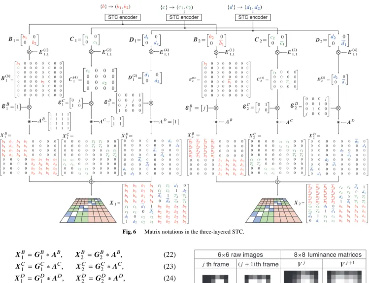
As shown at the top of Fig. 6, when two bitss1ands2, {s} ∈ {b,c,d}, from each of the bit streams are fed to the individual STC encoder, it outputs two matricesS1andS2, S ∈ {B,C,D}, which are of size 2×2 with the two bits located in the main diagonal, as
B1=
[b1 0
0 b2 ]
, B2=
[b2 0
0 b1 ]
, (9)
C1=
[c1 0
0 c2 ]
, C2 =
[c2 0
0 c1 ]
, (10)
D1 =
[d1 0
0 d2 ]
, D2=
[d2 0
0 d1 ]
. (11)
ForBi,Ci, andDi,i∈ {1,2}, we define expansion ma- trices with different sizes4×4,2×2, and1×1asE1,1(4),E(2)1,1, andE(1)1,1, respectively. Using these expansion matrices ac- cording to Eq. (4), we have
B(8)1 =B1⊗E(4)1,1, B(8)2 =B2⊗E(4)1,1, (12) C(4)1 =C1⊗E1,1(2), C(4)2 =C2⊗E1,1(2), (13) D(2)1 =D1⊗E(1)1,1, D(2)2 =D2⊗E(1)1,1, (14) where the elements of each matrix are seen in Fig. 6.
Then, in three-layered STC, we define the coding ma- trices operating on the first and second input matricesB(8)i , C(4)i , andD(2)i as
EB1 =[ 1]
, E2B=[
j]
, (15)
EC1 =
[0 j
1 0 ]
, EC2 =
[0 1
j 0 ]
(16)
E1D=
0 0 0 1 0 0 j 0 0 j 0 0 1 0 0 0
,ED2 =
0 0 0 j 0 0 1 0 0 1 0 0 j 0 0 0
. (17)
The encoding process in the spatial domain is done as GB1 =EB1 ⊗B(8)1 , G2B=E2B⊗B2(8), (18) GC1 =EC1 ⊗C(4)1 , GC2 =EC2 ⊗C(4)2 , (19) GD1 =ED1 ⊗D(2)1 , GD2 =ED2 ⊗D(2)2 , (20) where an 8×8 matrix GSi is formed by multiplying Si by each element ofESi. Note again that the j-operator indicates the binary opposite.
Then, convolvingGSi with convolution matrices defined as
AB=
1 1 1 1 1 1 1 1 1 1 1 1 1 1 1 1
, AC=
[1 1
1 1 ]
, AD=[
1]
, (21)
results in
Fig. 6 Matrix notations in the three-layered STC.
XB1 =G1B∗AB, X2B=GB2 ∗AB, (22) XC1 =GC1 ∗AC, XC2 =GC2 ∗AC, (23) X1D=G1D∗AD, XD2 =GD2 ∗AD, (24) where convolution we consider here is different from the normal one. Although in 2D convolution there are wide and narrow convolutions, the one considered here is a hybrid.
Zero padding is done for elements at top or left edges of the input matrix (i.e.,S) that does not have any neighboring elements to the top and left, while no zero-padding is done for elements at bottom or right edges of the input matrix. To put it more specifically, in convolvingGBof size4×4with ABof size4×4, narrow convolution is done by appending three rows and three columns with all zero elements toB.
Finally, the output matrices of the first and second du- rations are expressed as, respectively,
X1 =X1B+XC1 +X1D, (25) X2 =X2B+XC2 +X2D, (26) where the bits are spread over the8×8matrices, shown at the bottom of Fig. 6.
Two raw images of size6 ×6 in pixel are shown in Fig. 7, which is captured by high-speed camera operating at 1000 fps at 55 m away from an8×8LED array. They are re- sized to 8×8 luminance matrices, shown in Fig. 7, through bilinear interpolation. From the two luminance matrices, six bits are successfully extracted. The decision statistics are obtained as combinations of addition and subtraction of
Fig. 7 Two raw images with size6×6trimmed from the whole one and its’8×8luminance matricesVjandVj+1after resizing image processing are shown, when an8×8LED array was captured by the high-speed camera at the distance of 55 m. Reproduced from[24].
luminance values, though the detail is not mentioned here (see[24]). It was confirmed from Fig. 8 that the received bit stream of{b}is error-free all over the measured range, and the received bit streams of{c}and{d}are also error-free in the range D ≤ 155m and 55 m, respectively. This is a bit surprise that the sizes of the raw image of the LED array at 210 m, 155 m, and 55 m are 2×2, 2×2, and 5×5 pixels, respectively. This can be said a good example of exploiting spatial dimensions for extending the coverage of IS-based VLC.
It is shown in[43],[44]that applying spatial modula- tion (SM) into the L-STC allows to further increase in the reception rate without deteriorating the bit reception quality of the original L-STC.
Fig. 8 Measured BER of the three-layered and non-layered STC systems is shown as a function of the distancedof the receiver from the LED array, where the lens with the focal length 12.5 mm are used. Reproduced from [24].
5. Conclusion
This paper presented a survey on the novel type of VCL us- ing IS receivers. Current VLC receivers either use a PD or an IS for receiving the VLC signals. The use of PD is suit- able for stationary clients where its FOV can be aligned to the LED fixture for high received optical power. On the mobile devices or moving situations, the IS can be used since they have comparatively larger FOV (due to wider concentration lens), making the moving device more robust to movements and FOV misalignment. Due to a large num- ber of PDs operating inside IS might be slow and energy expensive. This is natural, given that IS was primarily de- signed for image and video capture, and not for receivers.
Thus, it is challenging to design an array transmitter and IS receiver pair to satisfy a diverse range of practical re- quirements, with robustness to device movements and FOV misalignment, making the most use of the 2D systems, for meritorious transmission techniques.
Acknowledgment
The author would like to thank Prof. Takaya Yamazato of Nagoya University for his insightful comments on an earlier version of this paper.
References
[1] M. Akanegawa, Y. Tanaka, and M. Nakagawa, “Basic study on traf- fic information system using LED traffic lights,” IEEE Trans. Intell.
Transp. Syst., vol.2, no.4, pp.197–203, Dec. 2001.
[2] H. Haas, L. Yin, Y. Wang, and C. Chen, “What is LiFi?,” J. Lightw.
Technol., vol.34, no.6, pp.1533–1544, Mar. 2016.
[3] P.H. Pathak, X. Feng, P. Hu, and P. Mohapatra, “Visible light com- munication, networking, and sensing: A survey, potential and chal- lenges,” IEEE Commun. Surveys Tuts., vol.17, no.4, pp.2047–2077, 4th Quater 2015.
[4] L. Zeng, D.C. O’Brien, H.L. Minh, G.E. Faulkner, K. Lee, D. Jung, Y. Oh, and E. T. Won, “High data rate multiple input multiple output (MIMO) optical wireless communications using white LED light- ing,” IEEE J. Sel. Areas Commun., vol.27, no.9, pp.1654–1662, Dec. 2009.
[5] Y. Wang, L. Tao, X. Huang, J. Shi, and N. Chi, “8-Gb/s RGBY LED- based WDM VLC system employing high-order CAP modulation and hybrid post equalizer,” IEEE Photon. J., vol.7, no.6, 7904507, Dec. 2015.
[6] H.B.C. Wook, S. Haruyama, and M. Nakagawa, “Visible light com- munication with LED traffic lights using 2-dimensional image sen- sor,” IEICE Trans. Fundamentals, vol.E89-A, no.3, pp.654–659, March 2006.
[7] M. Rubaiyat, H. Mondal, and J. Armstrong, “Analysis of the ef- fect of vignetting on MIMO optical wireless systems using spatial OFDM,” J. Lightw. Technol., vol.32, no.5, pp.922–929, May 2014.
[8] A. Dabbo and S. Hranilovic, “Receiver design for wireless optical MIMO channels with magnification,” Proc. ConTEL 2009, pp.51–
58, Zagreb, Croatia, June 2009.
[9] C. Danakis, M. Afgani, G. Povey, I. Underwood, and H. Haas, “Us- ing a CMOS camera sensor for visible light communication,” Proc.
IEEE Globecom Workshops 2012, pp.1244–1248, Anaheim, CA, USA, Dec. 2012.
[10] Y. Goto, I. Takai, T. Yamazato, H. Okada, T. Fujii, S. Kawahito, S.
Arai, T. Yendo, and K. Kamakura, “A new automotive VLC system using optical communication image sensor,” IEEE Photon. J., vol.8, no.3, 6802716, June 2016.
[11] K. Masuda, T. Yamazato, H. Okada, M. Katayama, and T. Fujii, “A proposal on hierarchical coding scheme of visible light communica- tion using led traffic lights,” Proc. ISITA 2004, pp.187–190, Parma, Italy, Oct. 2004.
[12] T. Yamazato, I. Takai, H. Okada, T. Fujii, T. Yendo, S. Arai, M.
Andoh, T. Harada, K. Yasutomi, K. Kagawa, and S. Kawahito,
“Image-sensor-based visible light communication for automotive applications,” IEEE Commun. Mag., vol.52, no.7, pp.88–97, July 2014.
[13] I. Takai, S. Ito, K. Yasutomi, K. Kagawa, M. Andoh, and S.
Kawahito, “LED and CMOS image sensor based optical wireless communication system for automotive applications,” IEEE Photon.
J., vol.5, no.5, 6801418, Oct. 2013.
[14] R.D. Roberts, “A MIMO protocol for camera communications (CamCom) using undersampled frequency shift on-off keying (UF- SOOK),” Proc. GLOBECOM Wkshps, pp.1052–1057, Atlanta, GA, USA, Dec. 2013.
[15] W. Du, J.C. Liando, and M. Li, “Soft hint enabled adaptive visible light communication over screen-camera links,” IEEE Trans. Mobile Comput., vol.16, no.2, pp.527–537, Feb. 2017.
[16] B. Xie, K. Chen, G. Tan, M. Lu, Y. Liu, T. He, and J. Wu, “LIPS:
A light intensity based positioning system for indoor environments,”
ACM Trans. Sensor Networks, vol.12, no.4, pp.1–27, 2016.
[17] T. Nguyen, C.H. Hong, N.T. Le, and Y.M. Jang, “High-speed asyn- chronous optical camera communication using LED and rolling shutter camera,” Proc. IEEE ICUFN 2015, pp.214–219, Sapporo, Japan, July 2015.
[18] VLCC [online] http://www.vlcc.net/modules/xpage1/?ml_lang=en [19] 802.15.7-2011–IEEE standard for local and metropolitan area
networks–Part 15.7: Short-range wireless optical communication using visible light.
[20] S. Haruyama and T. Yamazato, “Image sensor based visible light communication,” in Visible Light Communiction, S. Arnon Ed., ch.9, pp.181–205, Cambridge University Press, Cambridge, UK, 2015.
[21] T. Yamazato and S. Haruyama, “Image sensor based visible light communication and its application to pose, position, and range esti- mations,” IEICE Trans. Commun., vol. E97-B, no.9, pp.1759–1765, Sept. 2014.
[22] S. Arnon, Advanced Optical Wireless Communication Systems,
Cambridge University Press, Cambridge, UK, 2012.
[23] Z. Ghassemblooy, W. Popoola, and S. Rajbhandari, Optical wireless communications: System and channel modelling with MATLAB, CRC Press, Boca raton, FL, 2012.
[24] K. Ebihara, K. Kamakura, and T. Yamazato, “Layered transmis- sion of space-time coded signals for image-sensor-based visible light communications,” J. Lightw. Technol., vol.33, no.20, pp.4193–4206, Oct. 2015.
[25] A.E. Gamal and H. Eltoukhy, “CMOS image sensors,” IEEE Circuits Devices Mag., vol.21, no.3, pp.6–20, May/June 2005.
[26] L.J. Kozlowski, D.L. Standley, J. Luo, A. Tomasini, A.M. Gallagher, R. Mann, B.C. Hsieh, T. Liu, and W.E. Kleinhans, “Theoretical basis and experimental confirmation: Why a CMOS imager is superior to a CCD,” Proc. SPIE 3698, Infrared Technology and Applications XXV, pp.388–396, July 1999.
[27] J. Janesick and J. Tower, “Particle and photon detection: Counting and energy measurement,” Sensors, vol.16, no.5, 688, pp.1–17, May 2016.
[28] P. Ji, H.-M. Tsai, C. Wang, and F. Liu, “Optical vehicle-to-vehicle communication system using LED transmitter and camera receiver,”
Proc. IEEE VTC Spring 2014, pp.1–6, Seoul, Korea, May 2014.
[29] Y.-S. Kuo, P. Pannuto, K.-J. Hsiao, and P. Dutta, “Luxapose: Indoor positioning with mobile phones and visible light,” Proc. MobiCom 2014, pp.447–458, Maui, HW, USA, Sept. 2014.
[30] Y. Liu, K. Liang, H.-Y. Chen, L.-Y. Wei, C.-W. Hsu, C.-W. Chow, and C.-H. Yeh, “Light encryption scheme using light-emitting diode and camera image sensor,” IEEE Photon. J., vol.8, no.1, 7801107, Feb. 2016.
[31] E.F. Schubert, Light-Emiiting Diodes, 2nd Ed., ch.5, pp.93–97, Cambridge University Press, Cambridge, UK, 2006.
[32] S. Rajagopal, R.D. Roberts, and S.-K. Lim, “IEEE 802.15.7 visible light communication: modulation schemes and dimming support,”
IEEE Commun. Mag., vol.50, no.3, pp.72–82, March 2012.
[33] IESNA Lighting Handbook, 9th Edition, ch.27, Figure 27-4, IESNA, New York, 2000.
[34] G. Ntogari, T. Kamalakis, J.W. Walewski, and T. Sphicopoulos,
“Combining illumination dimming based on pulse-width modula- tion with visible-light communications based on discrete multitone,”
J. Opt. Commun. Netw., vol.3, no.1, pp.56–65, Jan. 2011.
[35] H.-J. Jang, J.-H. Choi, Z. Ghassemlooy, and C.G. Lee, “PWM-based PPM format for dimming control in visible light communication sys- tem,” Proc. CSNDSP 2012, pp.1–5, Poznan, Poland, July 2012.
[36] J.K. Kwon, “Inverse source coding for dimming in visible light communications using NRZ-OOK on reliable links,” IEEE Photon.
Technol. Lett., vol.22, no.19, pp.1455–1457, Oct. 2010.
[37] S.D. Perli, N. Ahmed, and D. Katabi, “PixNet: Interference-free wireless links using LCD-camera pairs,” Proc. ACM MobiCom 2010, pp.137–148, Chicago, IL, USA, Sept. 2010.
[38] M. Kinoshita, T. Yamazato, H. Okada, S. Arai, E. Souke, T. Yendo, T. Fujii, and K. Kamakura, “Motion modeling of mobile transmitter for image sensor based I2V-VLC, V2I-VLC, and V2V-VLC,” Proc.
GLOBECOM Wkshps 2014, pp.450–455, Austin, TX, USA, Dec.
2014.
[39] K. Ebihara, K. Kamakura, and T. Yamazato, “Layered space-time coding using LED array for image-sensor-based visible light com- munications.” Proc. IEEE ICC 2014, pp.5048–5053, London, UK, June 2015.
[40] T. Nguyen, N.T. Le, and Y.M. Jang, “Practical design of screen-to- camera based optical camera communication,” Proc. IEEE ICOIN 2015, pp.369–374, Siem Reap, Cambodia, Jan. 2015.
[41] S. Hranilovic and F.R. Kschischang, “A pixelated MIMO wireless optical communication system,” IEEE J. Sel. Topics Quantum Elec- tron., vol.12, no.4, pp.859–874, July/Aug. 2006.
[42] Y. Amano, K. Kamakura, and T. Yamazato, “Alamouti-type cod- ing for visible light communication based on direct detection using image sensor,” Proc. IEEE GLOBECOM 2013, pp.2430–2435, At- lanta, GA, USA, Dec. 2013.
[43] K. Masuda, K. Kamakura, and T. Yamazato, “Spatial modulation in layered space-time coding for image-sensor-based visible light communication„” Proc. PIMRC 2016, pp.1–6, Valencia, Spain, Sep.
2016.
[44] K. Masuda and K. Kamakura, “Spatial modulation for layered space-time coding used in image-sensor-based visible light commu- nication„” IEICE Trans. Commun., Special Issue on Visible Light Communications in Conjunction with Topics of ICEVLC 2015, Ar- ticle ID: 2016LCP0001, Dec. 2016.
Koji Kamakura received the B.E., M.E., and Ph.D. degrees in electrical engineering from Keio University, Yokohama, Japan, in 1997, 1999, and 2002, respectively. He is a Profes- sor at Department of Computer Science, Chiba Institute of Technology, Chiba, Japan. From 2002 to 2006, he was an Assistant Professor at the Department of Electronics and Mechanical Engineering, Chiba University, Chiba, Japan.
From 2006 to 2015, he was an Associate Profes- sor with the Department of Computer Science, Chiba Institute of Technology, Chiba, Japan. He was a Visiting Profes- sor at Heudiasyc, Université de Technologie de Compiègne, France, from April 2013 to March 2014. He was a Visiting Scientist at the School of Information Technology and Engineering, University of Ottawa, Ottawa, ON, Canada, in 2002 and 2003. From 2000 to 2002, he was a Special Re- searcher of Fellowships of the Japan Society for the Promotion for Science, for Japanese Junior Scientists. His research interests include optical com- munication theory and system analysis. He is a Member of the IEICE. He received the 14th Telecom System Technology Award for Students from the Telecommunications Advancement Foundation in 1999 and the Erics- son Young Scientist Award in 2002.