Effect of the ammonium groups on the
properties and stability of anion conductive
membranes
A Doctoral Thesis
Present to
Interdisciplinary Graduate School of Medicine and Engineering
University of Yamanashi
September 2017
Contents
Chapter 1
Background and Introduction
1.1 Background……… 1
1.1.1 Urgent demand for clean energy resources………... 1
1.2 Introduction………... 2
1.2.1 Anion exchange membranes as a viable alternative to protonic counterpart 2 1.2.2 Challenges of Anion exchange membranes………...……... 4
1.2.2.1 Ionic mobility (Low ionic conductivity)……… 4
1.2.2.2 Hydroxide ion transport (Conduction mechanism)……… 5
1.2.2.3 How to achieve high anionic conductivity without membrane swelling?... 6 1.2.2.4 Alkaline stability……… 7
1.2.2.4.1 Stability of the polymer backbone……….. 8
1.2.2.4.2 Stability of quaternary ammonium……… 9
1.2.2.5 Fuel cell Performance……… 11
1.2.2.5.1 Differences between AEM and PEM……… 11
1.2.2.5.2 Recent achievements in cell performance of AEMFC…………. 12
1.2.3 Synthetic strategies to enhance the properties of anion Exchange membranes…... 13 1.2.3.1 Approaches to stabilize the polymer backbones of AEMs……… 13
1.2.3.1.1 Block co-polymerization……… 14
1.2.3.1.2 Crosslinking…….……….. 15
1.2.3.1.3 Grafting of polymeric materials………...………. 16
1.2.3.1.5 Polyphenylene based AEMs……… 18
1.2.3.2 Effect of ammonium structure on properties of AEMs……… 19
1.2.3.2.1 Investigation of ammonium cations for low cost and Synthetic facility……… 21 1.3 Aim of the current study……….. 27
1.4 References……….. 28
Chapter 2 Effect of ammonium groups on the properties of anion conductive membranes based on partially fluorinated aromatic polymers 2.1 Introduction……… 35
2.2 Experimantal……… 35
2.2.1 Materials and methods……… 35
2.2.1.1 Materials……… 36 2.2.2 Synthesis of PE-bl-9……… 36 2.2.3 Chloromethylation of PE-bl-9……… 37 2.2.4 Quaternization Reactions……… 37 2.2.5 Ion Exchange……….. 38 2.2.6 Measurements……….. 38
2.2.7 Determination of IEC values……… 38
2.2.8 Water uptake and λ……….. 39
2.2.9 Conductivity measurements………. 39
2.2.10 Stability test……….. 40
2.3 Results and discussion……….. 40
2.3.1 Synthesis of QPE-bl-9 with various ammonium groups………. 40
2.3.3 Water uptake and anion conductivity……….. 54
2.3.4 Alkaline stability………. 58
2.3.5 Mechanical properties………. 64
2.4 Screening of new series of ammonium groups……….. 66
2.4.1 Ionic conduction and water management……….… 66
2.4.2 Morphology………. 67
2.4.3 Alkaline stability……….. 67
2.5 Conclusion………. 72
2.6 References……… 73
Chapter 3 High Hydroxide Ion Conductivity with Enhanced Alkaline Stability of Partially Fluorinated and Quaternized Aromatic Copolymers as Anion Exchange Membranes 3.1 Introduction……… 75
3.2 Experimental section……… 76
3.2.1 Materials………. 76
3.2.2 Synthesis of QPAF Membranes……… 76
3.2.3 Quaternization Reactions……… 76
3.2.4 Membrane Preparation……… 77
3.2.5 Ion Exchange Reactions………. 77
3.2.6 Measurements……… 77
3.2.7 Determination of IEC Values……… 78
3.2.8 Water Uptake and λ……… 78
3.2.9 Ion Conductivity Measurements……… 79
3.2.10 Calculation of the Diffusion Coefficients of Hydroxide Ions……… 79
3.2.12 Preparation of Catalyst Coated Membrane (CCM) and Fuel Cell Operation 80
3.3 Results and discussion……… 80
3.3.1 Synthesis of QPAF Polymers……….... 80
3.3.2 Morphology of QPAF Membranes……… 92
3.3.3 Water Uptake of QPAF Membranes……… 94
3.3.4 Ion Conductivity………. 95
3.3.5. Alkaline Stability……… 100
3.3.6 Mechanical Properties……… 109
3.3.7 Fuel Cell Performance……… 112
3.3.8 Conclusion……….. 114
3.4 References………. 115
Chapter 4 Conclusion and Future Prespectives 4.1 Conclusion……… 118
4.2 Comparison with the state-of-the-art AEMs………. 120
4.3 Challenges and Future Perspectives………... 126
4.4 References……….. 128
List of Publications……… 131
Meeting abstracts………. 132
Chapter 1
1
Chapter 1. Background and Introduction
1.1 Background
1.1.1 Urgent demand for clean energy resources
Nowadays, economics is completely dependent on fossil fuels including coal, oil and natural gas which are non-renewable resources and will be exhausted in the future.1 The energy provided by
fossil fuels release pollutants and hazardous emissions to animals and plants. These emissions (especially CO2) are the reason behind the global warming. On the other hand, all stages of fossil
fuel production, either mining, extraction, processing or transportation have suspicious risks for humans and ecosystems.1,2 The solution is to move quickly from fossil fuel to clean alternative
energy resources. One of the alternative solutions is to increase the use of nuclear power which has negligible emissions and considered as inexhaustible.3 However, the latter has the safety risks
of handling the radioactive wastes and the possibility of catastrophic accidents such as Fukushima nuclear power Plant, Japan 2011 and that of Chernobyl in the USSR in 1985 besides the high cost that hinder the widespread of nuclear power.3,4 Renewables (such as wind and solar energy) and
biomass are alternatives to clean energy resource with zero-emission greenhouse gases. However solar energy can be used directly through the radiating thermal and light energy, unfortunately, it requires complex technologies besides wide land and rare metal catalysis.1
Recently, much efforts have been directed towards the development of polymer electrolyte membrane based technologies for renewable energy storage and transformation; such as redox flow batteries, polymer electrolyte membrane fuel cells (Alkaline and acidic) or water electrolysis for hydrogen production.5 Among these applications, Fuel cells turned to be a viable clean energy
resource for mobile and stationary applications.6
Fuel cells are electrochemical system that combine hydrogen and oxygen to produce electricity, heat and water. Fuel cells are considered a flameless or zero-emission process compared to the fossil fuel combustion.Fuel cells can achieve two times and half higher efficiency than that in
Chapter 1
2
internal combustion engines. Moreover, fuel cell is a nearly silent process without moving parts.7
Different types of fuel cells have been developed including; anion exchange membrane fuel cells (AEMFCs), Proton exchange membrane fuel cells (PEMFCs), solid oxide fuel cells (SOFCs), molten carbonate fuel cell (MCFCs) and phosphoric acid fuel cells (PAFCs). Among them, PEMFCs and AEMFCs have gained more attention due to their low temperature (below 200 oC)
applications in stationary, vehicles and mobile devices.8,9
1.2 Introduction
1.2.1 Anion exchange membranes as a viable alternative to protonic
counterpart
PEMFCs have been excessively studied for several decades and found their way in different applications. However, in such strong acidic and corrosive medium, platinum group metal catalysis (Pt, Os, Ir, Ru, Rh and Pd) are mainly required due to their resistance under corrosive conditions. Unfortunately, the rarity and high cost of these precious metals, obstacle the wide commercialization of PEMFCs that devoted the scientist’s efforts towards the alkaline anion exchange membrane fuel cells (AAEMFCs). The alkaline environment of AAEMFCs permits faster electro-kinetics of the electrodes allowing the use of non-platinum group metals such as (Ag, Ni and Co).5,8,9Moreover, the alkaline conditions open the door for multi choices of fuels such as
hydrazine, ethylene glycol, alcohols and sodium borohydride besides the availability of H2 with
some impurities (PEMFCs requires high purity of H2).10 Due to these advantages, alkaline fuel
cells gained much more attention in the recent years as the next generation of fuel cell technology. AAEMFCs are mainly based on anion exchange membrane (AEM) in which the function is a little different than that of proton exchange membranes (PEM, i.e. Nafion). Figure 1-1, Shows a schematic diagram of the function of AEM in comparison to that of PEM.11 In the acidic fuel cells,
Chapter 1
3
conduction of H+ take place through the PEM by transferring the protons from anode to cathode
according to equations (1,2).
At anode: (1) At cathode (2)
While, in the alkaline fuel cells the solid AEM transfers the hydroxide ions from cathode to anode in which OH- oxidized to produce water as by product and electrons moving through external wire
resulting in electric current. (equations 3,4).
at anode: (3)
at cathode: (4)
In both cases the overall reaction is the same as shown in the following equation (5): (5)
Figure 1-1. Schematic diagram of Anion and proton exchange membrane fuel cells.11
Besides their application in fuel cells, AEMs found their way in different membrane-based energy conversion and storage devices such as reverse electro-dialysis, secondary batteries, desalination and water electrolysis (Figure 1-2).12,13 The membrane should meet essential requirements
depending on its application. In the fuel cell applications, AEM is considered the key part of the cell, since it allows and organizes the OH- transportation from cathode to anode, in addition, it
Chapter 1
4
ion conductivity, excellent chemical and mechanical properties under harsh alkaline conditions besides the low gas permeability.13 A standard AEM that fulfill all the aforementioned
requirements has not been reported. Thus, more efforts required to develop an applicable AEM.
Figure 1-2. Various applications of anion exchange membranes.14-17
1.2.2 Challenges of Anion exchange membranes
However the alkaline conditions allows the promising utilization of non-precious metal catalysis, AEMs face many challenges comparing to PEMs that will be summarized in the following lines:-
1.2.2.1 Ionic mobility (Low ionic conductivity)
One of the main challenges for AEMs is the lower ionic conductivity compared to proton conductivity in PEMs. Fundamentally, the mobility of hydroxide ions (20.64× 10⁻⁸ m2/sV) is much
lower than proton (36.23 × 10⁻⁸ m2/s V) in infinite diluted solution at 298 K. The lower mobility
of OH- may end to lower conductivity than that of proton. Moreover, the lower dissociation
constant of quaternary ammonium as a weak base (pKb = 4) compared to the strong acidic aryl
Chapter 1
5
However, recently some AEMs were reported to exhibit same level of conductivity to that of Protonic membranes specially at elevated temperature. Such as poly(phenylene oxide) based AEMs that exhibited 198 mS/cm at 90 oC which is as similar efficient conduction as that of Nafion
membranes.21 suggesting that at elevated temperature, OH- conduction can be as fast as H+ ions.
Another issue related to the exposure of AEM (OH- form) to CO
2 (air) even for short time, in which
the membrane can be exchanged to the lower conductive bicarbonate ion form leading to lower power density in fuel cell.13 In other words, when we handle the AEMs in air (CO
2), we treat with
membranes in bicarbonate ion form not hydroxide ion form.
1.2.2.2 Hydroxide ion transport (Conduction mechanism)
It was reported that proton and hydroxide ions follow Grøtthuss mechanism in aqueous solutions, however the details of two mechanisms are little different. 22-26 Hydronium ion (H
3O+) is naturally
form hydrogen bonding network with water without further activation or solvent rearrangement, while hydroxide ions tend to form stable solvation shells that try to reorganize the solvent molecules and perturb the hydrogen bond network. 18-22 In the literature, according to the transport
similarities it aqueous solution, it was hypothesized that hydroxide transport in AEMS could be
similar to that of PEMs that exhibit vehicle mechanism and Grøtthuss type mechanism, however the Grøtthuss mechanism is the dominant transport mechanism.13, 22
In the literature, many conduction mechanisms for hydroxide ions in AEMs, were suggested taking in to account the surrounding environment in the membrane and /or fuel cell in a similar way to that of PEMs. The hydroxide transport can be resulted of the combination of different mechanisms including: i) Grøtthuss mechanism via hydrogen and covalent bonds, ii) surface site hopping on membrane quaternary ammonium, iii) diffusion and migration mechanism due to the concentration or potential gradient on the charged particles and iv) convection mechanism due to the pressure gradient and /or electrostatic potential gradient of the mobile species (Figure 1-3).27-35 So that, the
Chapter 1
6
and/or potential gradient in the fuel cell.
Figure 1-3. Suggested conduction mechanisms in AEMs. 27
1.2.2.3 How to achieve high anionic conductivity without membrane swelling???
As described above, AEMs possess lower conductivity compared to the protonic membranes. Taking into account that the diffusion of H+ is four times higher than that of OH- ions, a fourfold
increase in hydroxide ion conductivity required to reach same performance of acidic polymer electrolytes.36 Demonstrating that AEMs need to carry four times higher IECs, so that many
attempts were devoted to increasing the conductivity of AEMs by increasing the ion exchange capacity (IEC). Unfortunately, that increase in IEC values come on to the account of membrane swelling. At high IECs, the membrane exhibit excessive water uptake to the level that permits the mechanical failure when the membrane fabricated in the fuel cell stack.13
Some synthetic strategies have been reported to mitigate the membrane swelling at high IECs such as crosslinking37 or block copolymerization38 achieving promising success in this regard. It was
reported that the good phase separation between hydrophilic and hydrophobic segments in most of these strategies is responsible for the balance between high conductivity (at high IEC) and low water uptake. Because of the water molecules are essential for efficient conduction and based on similarities in conduction mechanisms in both AEM and PEM as described above, It was found that better phase separation in the Nafion membranes permits the overlap between hydrophilic
Chapter 1
7
domains forming good interconnectivity between the ionic channels while in absence of phase separation (such as sulfonated polyetherketone (SPEEK)), a dead-end channels formed leading to tightly bound water molecules and lower conductivity as well (Figure 1-4) .13, 39, 40
Figure1-4. Shematic diagram of phase separation in NAFION and SPEEK membranes.40
1.2.2.4 Alkaline stability
The most critical challenge that face AEMs is the alkaline stability under strong alkaline conditions specifically at elevated temperatures (over 80 oC). Generally, AEMs are constructed of polymer
backbone tethered to quaternary ammonium (QA) via benzylic group that provide different locations for alkaline attack by OH- ions either in polymer main chain, benzylic tether or
quaternary ammonium (QA) (Figure 1-5). So that the stability of AEMs is mainly dependent on the chemical stability of polymer backbone and QA as well. 13
Chapter 1
8 Figure 1-5. Possible degradation pathways of AEMs.
1.2.2.4.1 Stability of the polymer backbone
Fundamentally, the stability of polymer backbone depends on the chemical structure of the polymer main chain. Some polymer backbones are susceptible to alkaline attack more than others. For example, poly(arylene ether) (PAE) that contains C-O bond is prone to degradation more than polyphenylenes or polystyrenes.41,42 A computational and experimental study by Yoong-Kee et. al.,
demonstrated that PAE degraded faster than QA since the barrier energy for aryl-ether degradation was 85.8 kJ/mol compared to 90.8 kJ/mol for QA degradation (Figure 1-6).43 The results suggested
62 % degradation of aryl-ether and 12% of BTMA in 0.5M NaOH at 80 oC for 2h.43
Figure 1-6. The possible degradation of poly(arylene ether) backbones.43
Also the ether bond free backbones can undergo degradation or chemical transformation in alkaline medium, such as poly(vinylidene fluoride) (PVDF) that undergo E2 elimination when be attacked by OH- ions (Figure 1-7a).44 Moreover, polystyrenes can be oxidized in presence of alkali to form
Chapter 1
9
carboxylic acid (Figure 1-7b).45 The backbone degradation or transformation almost affect the
mechanical properties of the membrane as well as conductivity and cell performance.13
Figure 1-7. Possible degradation of (a) PVDF backbone and (b) Oxidative carboxylation of
polystyrenes.44, 45
1.2.2.4.2 Stability of quaternary ammonium
The quaternary ammonium as the ion conducting component in AEMs, undergoes many degradation mechanisms that were extensively discussed in the literature, however the most accepted pathways are nucleophilic substitution (SN2) and Hofmann elimination (E2). In SN2 mechanism, OH- ions attack α-carbon either in the tether (benzylic sites) as shown in (Figure 1-8),
or in the pendant methyl groups of QA (Figure 1-9) to produce amine and alcohol in both cases. This degradation pathway usually leads to complete loss of QA resulting in decrease in ion exchange capacity (IEC) and conductivity.46
N H3C CH3 CH3 OH -N H3C CH3 OH CH 3 +
Figure 1-8. Tether degradation mechanism of AEMs via nucleophilic substitution.46
Chapter 1
10
Figure 1-9. Pendant quaternary ammonium degradation via Nucleophilic substitution (SN2).46
The E2 mechanism takes place when the QA possess β-hydrogen, in which OH- attack that
β-hydrogen resulting in formation of amine and alkene (Figure 1-10). One or both of SN2 and E2 mechanisms occur in presence of α- and β-positions depending on the chemical structure. For example, the steric hindrance or bulky structure at one position favor the degradation at the other position.47
Figure 1-10. Alkaline degradation via Hofmann elimination (E2).47
Stevens and Sommelet-Hauser rearrangements (Figures 1-11, 1-12) were also suggested via formation of intermediate ylides (C-__N+(R)
3), however the degradation via Stevens and
Sommelet-Hauser rearrangements have been only observed on BTMA in aqueous alkaline conditions but have not been experimentally detected in AEM materials.13, 48-50
Chapter 1
11
Figure 1-11. possible degradation of AEMs via Summelet-Hauser rearrangement.49
Figure 1-12. Possible degradation of AEMs via Stevens rearrangement.50
1.2.2.5 Fuel cell Performance
1.2.2.5.1 Differences between AEM and PEM
Fuel cell performance is considered the crucial property for AEMs, since the main objective of the research on AEMs is to obtain the durable and high performance AEM in practical fuel cell. However, the overall reaction for AEMFC and PEMFC is the same as described above, some main differences between the alkaline and acidic fuel cells should be considered. The first noticeable difference is the solid membrane that is fabricated with catalyst layer in each case. Usually AEM is used for alkaline cell in which OH- transport from cathode to anode, while PEM conducts H+
from anode to cathode in PEMFC (Figure 1-1). Another difference is the water management in alkaline and acidic fuel cells. In AEMFC, water is produced at the anode and consumed as direct reactant at cathode side, while in PEMFCs, water is generated at cathode side as byproduct.13,51
Chapter 1
12
Suggesting that hydration levels at cathode side is critical for AEMFCs. It was reported that low hydration levels in AEMFC specially at cathode side accelerated the degradation levels and decreased the stability of AEM.52
The main advantage of AEMFCs in comparison to PEMFC is that at high pH environment, the oxygen reduction reaction (ORR) is much faster than that in acidic medium of PEMFC, that permits the use of cheaper non-precious metal catalysis besides the availably of different fuel choices as described above.8-10
1.2.2.5.2 Recent achievements in cell performance of AEMFC
From the aforementioned differences between AEM and PEM, it seems that the lower conductivity and stability issues of AEMs are critical factors that may hinder achieving comparable power density to that of PEMFCs.13 However, recently, a significant advance in the conductivity and
stability of AEMs has been achieved that enabled high and comparable fuel cell performance to that of PEMFCs. Very recently, Varcoe et. al.53 reported aliphatic-heterocyclic benzyl-quaternary
ammonium radiation-grafted AEM with maximum power density of 980 and 800 mW/cm2 with
and without 0.1 MPa back pressurization, respectively using PtRu/C anodes and Pt/C cathodes and polysulfone ionomer in H2/O2 at 60 oC .53 Scott and coworkers, also reported QA radiated grafted
AEMs with maximum power density up to 823 mW/cm2 with O
2 and 500 mW/cm2 in air at 60 oC.54 Also, Kim reported polyphenylene based AEM with high power density up to 577 mW/cm2
and 450 mW/cm2 at 80 oC with H
2/O2 and air respectively.55 More interestingly, a platinum-free
hydrazine fuel cell based on poly(arylene ether) AEM achieved a high power density up to 510 mW/cm2 with hydrazine as fuel and O
2 as oxidant.56 These high power densities are among the
best reported in the literature and are considered comparable or higher than those reported for PEMFCs, suggesting that AEMs are not inferior to PEMs.10
In spite of the promising fuel cell performance, the long term durability of these AEMs was not carefully investigated due to the critical concerns related to the membrane stabilities and conductivity, especially at high temperatures and low hydration levels.13
Chapter 1
13
So that many efforts have been reported to improve the stability and conductivity of AEMs.
1.2.3 Synthetic strategies to enhance the properties of anion exchange
membranes
The state-of-art proton exchange membranes such as Nafion from DuPont, still higher conductive and more chemically and mechanically stable than the existing AEMs that almost hinder the practical commercialization of alkaline fuel cells. In the last decade, many approaches have been reported in the literature to address these drawbacks.57
Typical AEMs are composed of polymer backbone (ca. hydrophobic segment) tethered with organic cations (ca. hydrophilic segment) such as ammonium, sulfonium or phosphonium groups. Hydrophobic segments represented in polymer backbones contribute to membrane forming capability, gas impermeability, mechanical and thermal stability, while hydrophilic onium groups serve as ion exchangeable sites for anion conduction.57
Many approaches have been reported to investigate the effect of polymer backbone and cationic groups on properties of AEMs which will be discussed below.
1.2.3.1 Approaches to stabilize the polymer backbones of AEMs.
A number of aromatic polymers have been investigated for AEMs such as poly(phenylene oxide)s (PPOs)58 and poly(arylene ether sulfone)s (PAESs),59,60 and their copolymers. These polymers
could be easily synthesized via nucleophilic substitution polymerization reaction, however, arylene ether bonds are likely to be degraded under the basic conditions (Figure 1-13).61 For example,
polysulfone based AEMs broke after 168 h in 2 M KOH at 60 ºC due to the aforementioned backbone degradation (section 1.1.3.4).41
Chapter 1
14
Figure 1-13. chemical structure of poly (phenylene oxide) and poly (arylene ether sulfone).58,59
Mohanty et. al.62 has reported a study on the stability of various polymer backbones through the
analysis of the molecular weights before and after alkaline treatment. The results demonstrated that the presence of electron-withdrawing groups such as sulfone near to the arylene-ether proximity lead to severe degradation in the polymer main chain. However, some structural change or side reactions detected for substituted PPOs, While no detectable degradation was observed for ether-free backbones such as poly (biphenyl alkyene)(PBPA) and polystyrene-b-poly(ethylene-co-butylene)-b-polystyrene (PSPEB).62
Due to the low cost and facile synthesis of PAE or PAES backbones, many efforts have been devoted to improving the properties of AEMs based on these backbones, such as block copolymerization, crosslinking, grafting or alkli-dopping.
1.2.3.1.1 Block co-polymerization
The block copolymerization was reported as effective method to improve the morphology of the membranes and mitigate the water uptake, however, the achievements of this strategy in alkaline stability was limited. For example, Yokota et. al. reported that PAE based AEMs synthesized via block copolymerization, degraded after 50 h in 1M KOH at 40 o C.63 Separately when he used PAE
with oligophenylene moieties in the hydrophilic segments, the alkaline stability improved to some extent (lost 45% of its conductivity after 1000 h at the same conditions).56 Aslo Dong et. al.
reported that the PAES based AEMs bearing bis-quaternary ammonium degraded after 240 h in 1M KOH at 60 oC suggesting the low alkaline stability in spite of its high conductivity.64
Chapter 1
15 1.2.3.1.2 Crosslinking
Crosslinking of AEMs was also effective strategy to achieve the balance between water uptake and high conductivity besides the robust mechanical properties.37 Crosslinking was also promising to
improve the stability of PAE, PAES and PPO based AEMs. Recently, Lee et. al.65 reported that the
end group cross-linking via thermal treatment of PAES functionalized with imidazolium groups (Figure 1-14) helped to improve the alkaline stability of the membrane since the cross-linked membrane retained 68% (67 mS/cm) of its initial conductivity in 1M NaOH at 80 oC for 500h,
compared to 35% (27 mS/cm) of uncross-linked membrane.65
Figure 1-14. Chemical reaction of end group Crosslinking strategy of poly(arylene eteher
sulfone).65
Poly (phenylene oxides) (Figure 1-13a) as AEMs gained more attention due to their availability and facile bromination of methyl groups avoiding the toxic and carcinogenic chloromethylation reagents.44 Crosslinking was also effective stategy to enhance the stability of PPO-based AEMs.
Hickner and coworkers reported that the crosslinking of PPO based AEMs via thiol-ene click chemistry, mitigated the membrane degradation to some extent (Figure 1-15). Through the allakine treatment at 80oC for 500 h, the crosslinked membranes exhibited 27% and 52% loss of
conductivity in 1M and 4M NaOH respectively, while the uncross-linked membranes lost 57% and 73% of their conductivity in 1M and 4M NaOH respectively, demonstrating the positive effect of crosslinking on membrane properties.66
Chapter 1 16 O O N+ N+ S S O O N+ N+
Figure 1-15. Crosslinked PPO-based AEMs via thiol-ene click chemistry.
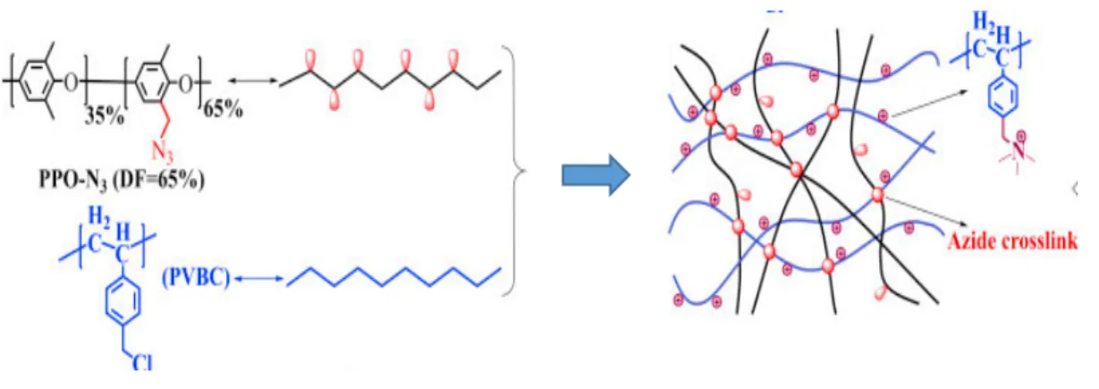
Another crosslinking method was applied by Xue et. al.67 using PPO containing azide groups
(PPO-N3) as macromolecular crosslinker for poly (vinylbenzyl chloride) (PVBC) based AEMs.
The membrane was prepared by photo crosslinking via UV-irradiation followed catsting, quaternizatin and alkylation (Figure1-16). The resulted membrane showed good alkaline stability with 15 % loss of conductivity in 1M NaOH at 80 oC for 500 h, while the uncross-linked membrane
lost 58% of its conductivity at the same conditions.67
Figure 1-16. preparation of crosslinked PVBC- based AEMs using macromolecular PPO-N3
cross-linker.67
1.2.3.1.3 Grafting of polymeric materials
Grafting of a commercially available polymer or a synthesized polymeric materials was reported as one one the successful approaches to improve the stability and conductivity of AEMS.68,69 Ran
Chapter 1
17
et. al reported that grafting PPO copolymers by poly (quaternary 4-vinylbenzyl chloride) (PPO-g-QVBC), significantly improved the conductivity and alkaline stability of the membrane (Figure 1-17). PPO-g-QVBC based AEM retained 80% of its conductivity and IEC values after 550 h in 2M NaOH at 60 oC and without further loss up to 1440 h. While conventional PPO based AEMs lost
60% of IEC values at the same conditions.68
Figure 1-17. Synthesis of the poly (phenylene oxide) grafted by poly (quaternary 4-vinylbenzyl
chloride) (PPO-g-QVBC).68
Pandey et. al. prepared (PPO-g-QVBC) membranes through the processing by solvent casting and melt pressing. The resulted membrane showed a good stability, since it exhibited only 3% loss of conductivity after in 1M KOH at 80 oC for 12 days.69
1.2.3.1.4 Alkali doped based AEMs.
The quaternized poly (benzimidazole) (PBI) was unstable in alkaline medium over 60oC, due to
alkaline attack at C2 position of imidazolium ring.70 However, another series of AEM based on
alkli-dopped PBI, have been reported and exhibited excellent alkaline stability since it retained the high conductivity in 1M NaOH even at 100 oC over 1000 h (Figure 1-18).71 Unfortunately, the
alkali bounded to PBI via hydrogen bonds gradually released in long term fuel cell operation, resulting in significant decrease in conductivity and voltage loss of the cell.72 Another challenge is
Chapter 1
18
high boiling point polar solvents.72
Figure 1-18. Alkali-dopped poly(2,5-benzimidazole) based AEM.72
1.2.3.1.5 Poly (phenylene) based AEMs
Recently, a relatively stable AEMs were simply synthesized in absence of grafting or crosslinking. This kind of membranes composed of polymer backbones containing no ether, ketone or sulfone bonds in the main chain that provide long durability in alkaline medium. Hibbs et. al. succeeded to synthesize the polyphenylene based AEMs without heteroatoms, ether, ketone or sulfone groups (Figure 1-19a), so that the membrane exhibited excellent stability even in 4 M KOH at 90 ºC for 336 h without change in IEC and 5% loss in conductivity.73
Also Bae and coworkers synthesized AEMs free of heteroatoms and ether groups based on poly (biphenyl alkylene) via free metal catalysis using acid condensation of trifluoroketones and biphenyls (Figure 1-19b). Poly (biphenyl alkylene)-based AEMs showed excellent alkaline stability since it survived for 720 h in 1M NaOH at 80 ºC with negligible change in IEC and conductivity.74
Figure 1-19. Chemical structures of a) poly phenylene and (b) poly(biphenyl alkylene).73, 74
(a) (b) C CF3 N+ OH -C CF3 CF3 x y n
Chapter 1
19
Another stable polymer backbone free of ether linkages based on fluorene structure has been reported (Figure 1-20).75 The fluorene-based membranes exhibited excellent alkaline stability
since the 1 H NMR data of the membranes after 30 days in 1M NaOH at 80 o C, showed no evidence
for degradation suggesting the long durability of these membranes in alkali. The stability of fluorene-based AEMs is attributed to both lack of ether bonds and long spacing between polymer backbone and quaternary ammonium (which will be discussed in detail in the next section).75
Figure 1-20. Chemical structure of fluorene-based AEMs.75
From the previous studies, a significant variation in the membrane properties and specifically in the resistance towards strong alkali, was observed by changing the polymer backbone, synthetic strategy or functionalization method. However, the standard AEM has not been reported. So that, many research attempts have been devoted to different strategy, that is investigating the optimum cationic group for the suitable polymer backbone.
1.2.3.2 Effect of ammonium structure on properties of AEMs
The quaternary ammonium moieties (QA), as the most common cation, play the main role as the ion exchangeable sites on the polymer main chain which are responsible for the ionic conduction of the AEMs. However, the degradation of QA in alkaline medium via different degradation pathways (See section 1.1.3.4) represent the main challenge for the scientists that hinder the commercialization of the alkaline fuel cell until now. Basically AEMs are functionalized by different cationic species such as quaternary ammonium (QA), phosphonium and sulfonium. QA
Chapter 1
20
was found to be more chemically and mechanically stable than phosphonium and sulfonium.76
There have been a few reports on sulfonium based-AEMs due to their low alkaline and thermal stability than that of QAs (Figure 1-21). 77, 78
Figure 1-21. Chemical structure of sulfonium based AEM.78
On the other hand, Phosphonium cations exhibited different stability according to the chemical structure. For example, Arges et. al. reported that polysulfone functionalized by trimethylphosphonium degraded faster than trimethylammonium counterpart.79
However, increasing the steric hinderance around phosphonium cation, enhanced the stability to some extent. For example, polysulfone functionalized with bulky Tris(2,4,6-trimethoxyphenyl) phosphonium cation maintained its initial conductivity and flexibility for 30 days in 1M KOH at 60 oC (Figure 1-22).80,81 On contrast, Ramani and coworkers reported in study using 2D-NMR
analysis that phosphonium cations degraded more rapidly than QA via Summelet-Hauser rearrangement and direct nucleophilic attack.82
Chapter 1
21
Figure 1-22. Chemical structure tris (2,4,6-trimethoxyphenyl) phosphonium based AEM.80
Recently, tetrakis (dialkylamino) phosphonium functionalized polyethylene based AEM exhibited excellent stability in 1M KOH at 80 oC for 22 days maintaining 82% of its conductivity (Figure
1-23).83The excellent stability is attributed to the charge delocalization on the phosphonium cation.
Unfortunately, this membrane was prepared by multi-step synthesis (six steps) that may increase the cost and hinder its commercialization.
Figure 1-23. Chemical structure of Phosphonium based AEMs.83
1.2.3.2.1 Investigation of ammonium cations for low cost and synthetic facility.
A variety of ammonium cations have been suggested in the literature, such as ammonium,84
Chapter 1
22
cations90.Some are claimed to be stable under harsh conditions (e.g., highly concentrated alkaline
solution) for substantial period of time,57 however, the most common ionic groups for AEMs are
quaternary ammonium groups (QAs) because of the low cost and facile synthesis via direct quaternization of benzylic or alkyl halides, and their reasonable stability if they are properly attached to the polymer structure.57
Substituents and electronic structure of the ammonium groups strongly affect the properties and stability of the AEMs. The alkaline stability of QAs has been extensively studied with small model compounds or polymer membranes. For example, Marino et al. reported the stability of various ammonium compounds under harsh alkaline conditions (in 6 M NaOH at 160 ºC) and concluded that 6-azonia-spiro [5, 5]undecane (ASU) was the most stable QA since it exhibited the longest half-life (110 h) among the tested groups under harsh alkaline conditions at 160 oC in 6M
NaOH (Figure 1-24).91
Figure 1-24. Comparison between the stability of different cations.91
Such spiro-cyclic ionic groups, when incorporated into the polymer backbone, improved significantly the alkaline stability of the AEM up to 1896 h at 80 ºC in 1 M KOD/D2O but a sign
of degradation was observed at 120 oC.91 Unfortunately, these copolymers were readily soluble in
water that may hinder their effective fabrication in alkaline fuel cells. So that, the membrane was blended with commercial poly (benzimidazole) by ionic crosslinking to improve its mechanical properties.92
Chapter 1
23
Figure 1-24. Spiro-cylic ionic groups incorporated in the polymer main chain.92
However, when the same ionic groups were attached to aromatic PAES backbone (Figure 1-25), the degradation occurred more easily even at 40 ºC due to the benzylic sites prone to nucleophilic attack by hydroxide ionsbesides the susceptibility of PAES backbone to alkaline attack (see section 1.1.3.4.1).89
Figure 1-25. Synthesis of spiro-cyclic based AEMs attached to polymer.89
Bae and his coworkers93 reported mechanistic study for another series of cationic groups (Figure
1-26) and revealed that the alkyl spacer substituted QAs (aliphatic and/or bulky alicyclic) were more alkaline stable than benzylic-substituents. The reason is attributed to the steric hindrance of side chains around the ammonium cation, besides lack of the de-shielding effect of main chain aromatic rings when QA stay far from aromatic proximity.93
Chapter 1
24
Figure 1-26. Schematic diagram for the alkaline stability of various cationic groups.93
Jannasch et al.94 also reported that long aliphatic groups directly attached to benzylic sites or as
spacers between the polymer backbone and the ammonium groups contributed to stabilizing the resulting PPO based AEMs. Constructing the flexible aliphatic chains as spacer and as extender chains on the QA (Figure 1-27), provided the free bath for effective ionic conduction and significantly improved the stability without detectable degradation up to 196 h in 1M NaOH at 80
oC.94
Figure 1-27. Chemical structure of PPO based AEMs with pendant alkyl side chains or flexible
Chapter 1
25
Li et al.95 supported the same idea for a different type of AEM based on polypropylene with long
alkyl spacer in the side chain and on QA. The copolymers were prepared by heterogeneous Ziegler-Natta catalyst mediated polymerization and the membranes was prepared by melt pressing in bromo methyl form followed by quaternization method at 160 oC or thermally crosslinked at 220 oC using styrenic diene crosslinker. Both cross-linked and noncross-linked membranes exhibited
excellent stability since it retained more than 85% of conductivity even in 5 M or 10 M NaOH at 80 ºC for 700 h (Figure 1-28).95
Figure 1-28. Chemical structure of polypropylene based AEMs with alky spacers QA.95
In contrast, an accelerated stability test for a model compound to PPO structure demonstrated that both of benzylic and alkyl spacer QAs degraded at the same rate when exposed to 4 equivalents of NaOCH3 in DMSO-d6/CDOD3 (20:1) solution at 80 ºC for 48 h.62 Moreover, Ramani et al.96
reported that alkyl spacing QAs were not suitable since PPO functionalized with hexyl spacer (using different synthetic method from the previous reports94) degraded faster than the
Chapter 1
26
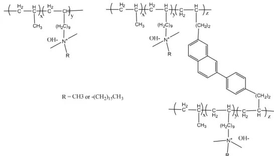
Recently, insertion of pendant aliphatic chains to QAs attached to the polymer backbone was found to play an important role in developing the phase-separation and water utilization as well as enhancing the stability of AEMs.97 In this regard, Binder et al. reported that PPO functionalized
with pendant alkyl group (C16) achieved good alkaline stability after 500 h in 1 M NaOH at 80 ºC maintaining 80% of its initial conductivity.98 In a separate study, Hickner et al. investigated the
effect of flexible alkyl spacer from C6 to C16 on PPO backbones and found that all spacers enhanced the stability and conductivity compared with BTMA counterpart.99 C6-C16 spacing
possessed good alkaline and mechanical stability even after 2000 h in 1 M NaOH at 80 ºC, maintaining 80% of their initial conductivity (Figure 1-29). Recently, a review by Kreuer100
concluded that the most promising approach to enhance the alkaline stability of AEMs is using alkyl spacers around the ammonium groups either tethered to amine or separated from polymer chain, which were likely to increase the steric shielding and mitigate the attack by the hydroxide anions.100
Figure 1-29. Chemical structure of poly (phenylene oxide) functionalized with pendant alkyl chain
on quaternary ammonium.99
The inconsistent results on the stability of polymer backbones and ionic groups suggested that the effects of ionic groups as well as the polymer backbones had to be more carefully investigated for improving the stability of AEMs.57
Chapter 1
27 1.3 Aim of the current study
Looking at the previous studies on anion conductive membranes for alkaline fuel cells as described above, it seems that the alkaline stability is the most critical challenge for AEMs due to the complex situation of the degradation mechanisms either from the polymer main chain or from quaternary ammonium. In our group, the polymer backbone of AEMs was extensively studied and different polymer structures have been investigated and recently it was found that the presence of ether bonds near to hydrophilic proximity, accelerated the degradation rate of the membranes.63
So that, a new class of polymers were developed, based on oligophenylene moieties in hydrophilic segments such as poly(arylene ether) block copolymer based AEM (QPE-bl-9) and partially fluorinated aromatic copolymer (QPAF).56, 101 In particular, QPE-bl-9 and QPAF membranes
exhibited high anion conductivity and good mechanical stability.However, the membranes lost most of its anion conductivity in 1 M KOH at 60 or 80 ºC within several hundred hours due to the decomposition of BTMA groups.56, 101 From the previous studies, the structure of ammonium
groups plays effective role in the properties and stability of AEMs. For a distinct polymer structure, optimizing the suitable cation is a main challenge to enhance the properties of the resulted membranes. The objective of the present study is to investigate the effect of different ammonium structures on the properties and stability of two reported oligophenylene based AEMs (QPE-bl-9 and QPAF).
In chapter 1, QPE-bl-9 membrane was selected to investigate the influence of various ammonium structures on its properties due to its high conductivity, mechanical stability and good cell performance. The ammonium structures include the common trimethylamine (TMA), dimethylhexylamine (DMHA) stabilized by steric factor of pendant alkyl chain. I also selected some structures stabilized by steric factor of bulky structure such as dicyclohexylmethlamine (DCHMA) and tributylamine (TBA) and finally another heterocyclic groups were selected that stabilized by resonance and charge delocalization; methylimidazole (MIm) and dimethylimidazole (DMIm). The PE-bl-9 copolymers and chloromethylated copolymer (CMPE-bl-9) were prepared according to the literature56 then the membranes were prepared through casting and Menshutkin
Chapter 1
28
reaction with different amines. The membrane properties were carefully studied through the NMR analysis, TEM images, conductivity and water uptake measurements and alkaline stability testing besides the mechanical properties through DMA analysis. The ammonium structures under investigation are expected to improve the properties of QPE-bl-9 membranes such as conductivity and alkaline stability.
In Chapter 2, The results in chapter 1, motivated me to investigate the effect of pendant aliphatic ammonium groups on the properties of partially fluorinated and aromatic copolymer AEM (QPAF). To elucidate the effect of flexible aliphatic ammonium groups onto the properties of QPAF membrane, two ammonium structures with pendant alkyl chains were selected; dimethylbutyl amine (DMBA) and dimethylhexylamine (DMHA). The results were compared with the common BTMA and heterocyclic structure (1,2-dimethylimidazolium). The membrane properties were carefully studied through the detailed examination of the morphology, ion conductivity, and alkaline and mechanical stability besides the fuel cell performance. It is expected that the new ammonium structure may enhance the stability and performance of QPAF membranes.
1.4 References
1- Jaccard, M. Sustainable Fossil Fuels: The Unusual Suspect in the Quest for Clean and Enduring Energy; Cambridge University press, 2006.
2- Greene, D.; Kahn, J.; and Gibson, R. Energy J. 1999, 20, 1–31.
3- Williams, S. R. Nuclear and Alternative Energy Supply Options for an Environmentally Constrained World: A Long-Term Perspective,” in Leventhal, P.; Dolley, S.; and Tanzer, S. Nuclear Power and the Spread of Nuclear Weapons: Can We Have One Without the Other?; Washington, D.C.: Brassey’s Inc., 2002.
Chapter 1
29
5- Li, N. W.; Guiver, M. D. Macromolecules 2014, 47, 2175-2198.
6- Lu, S.; Pan, J.; Huang, A.; Zhuang, L.; Lu, J. Proc. Natl. Acad. Sci. USA 2008, 105, 20611–20614.
7- Hoffmann, P.; Dorgan, B. Tomorrow's Energy: Hydrogen, Fuel Cells, and the Prospects for a Cleaner Planet; Cambridge, Massachusetts (The MIT Press), 2012.
8- Borup, R.; Meyers, I.; Bryan, P. Chem. Rev. 2007, 107, 3904-3951.
9- Wang, Y.-J.; Qiao, J.; Baker, R.; Zhang, J. Chem. Soc. Rev. 2013, 42, 5768-5787. 10- Shin, D. W.; Guiver, M. D.; Lee, Y. M. Chem. Rev. 2017, 117, 4759–4805. 11- Chen, J.; He, G.; Zhang, F. Int. J. Hydr. Enrg. 2015, 40, 7348-7360. 12- Li, N. W.; Guiver, M. D. Macromolecules 2014, 47, 2175-2198.
13- Varcoe, J. R.; Atanassov, P.; Dekel, D. R.; Herring, A. M.; Hickner, M. A.; Kohl, P. A.; Kucernak, A. R.; Mustain, W. E.; Nijmeijer, K.; Scott, K.; Xu, T. W.; Zhuang, L. Energy Environ. Sci. 2014, 7, 3135-3191.
14- Wang,Y.; Zhang, Z.; Jiang, C.; Xu, T. Ind. Eng. Chem. Res. 2013, 52, 18356−18361. 15- : Rahman, F.; Skyllas-Kazacos, M. J. Power Sources 2009, 189, 1212–1219.
16- : Carmo, M; Fritz, D. L.; Mergel, J.; Stolten, D. Int. J. Hydrogen Energy. 2013, 38, 4901‐4934. 17- Published by Smithsonian Institution, 2017. “Fuel cell Basics : Alkli fuel cells”,
http://www.americanhistory.si.edu/fuelcells/basics.htm
18- Dean, J. A. Lange’s Handbook of Chemistry, 15th ed.; McGrawHill: New York, 1999.
19- Vanysek, P. Ionic Conductivity and Diffusion at Infinite Dilution. In CRC Handbook of Chemistry and Physics, 83rd ed.; Lide, D. R., Ed.; CRC Press: Boca Raton, FL, 2002.
20- Zhang, Z. C.; Chalkova, E.; Fedkin, M.; Wang, C.; Lvov, S. N.; Komarneni, S.; Chung, T. C. Macromolecules 2008, 41, 9130−9139.
21- Ran, J.; Wu, L.; Wei, B.; Chen, Y.Y.; Xu, T.W. Sci. Rep. 2014, 4, 6486. 22- Grew, K. N.; Chiu, W. K. S. J. Electrochem. Soc. 2010, 157, B327−B337. 23- Marx, D. ChemPhysChem, 2006, 7, 1848.
Chapter 1
30
24- Tuckerman,M.; Laasonen, K.; Sprik, M.; Parrinello, M. J. Chem. Phys. 1995, 103, 150. 25- Tuckerman, M.; Laasonen, K.; Sprik, M.; Parrinello, M. J. Phys. Chem. 1995, 99, 5749. 26- Asthagiri, D.; Pratt, L. R.; Kress, J. D.; Gomez, M. A. Proc. Natl. Acad. Sci. U.S.A. 2004, 101,
7229.
27- Barbir, F. PEM Fuel Cells Theory and Practice, Elsevier, Burlington, MA, 2005. 28- Thampan, T.; Malhotra, S.; Tang, H.; Datta,R. J. Electrochem. Soc. 2000, 147, 3242. 29- Commer, P.; Cherstvy, A. G.; Spohr, E.; Kornyshev, A. A. Fuel Cells 2002, 2, 127. 30- Choi, P.; Jalani, N. H.; Datta, R. J. Electrochem. Soc. 2005, 152, E84.
31- Choi,P.; Jalani, N. H.; Datta, R. J. Electrochem. Soc. 2005, 152, E123.
32- Paddison, S. J.; Paul, R.; Zawodzinski, T. A.; Jr. J. Electrochem. Soc. 2000, 147, 617. 33- Paddison, S. J.; Paul, R. Phys. Chem. Chem. Phys. 2002, 4, 1158.
34- Weber, A. Z.; Newman, J. J. Electrochem. Soc. 2003, 150, A1008. 35- Weber, A. Z.; Newman, J. J. Electrochem. Soc. 2004, 151, A311.
36- Wang, Y.-J.; Qiao, J.; Baker, R.; Zhang, J. Chem. Soc. Rev. 2013, 42, 5768-5787.
37- Zhu, L.; Zimudzi, T. J.; Li, N.; Pan, J.; Lina, B.; Hickner, M. A. Polym. Chem. 2016,7, 2464-2475.
38- Tanaka, M.; Fukasawa, K.; Nishino, E.; Yamaguchi, S.; Yamada, K.; Tanaka, H.; Bae, C.; Miyatake, K.; Watanabe, M. J. Am. Chem. Soc. 2011, 133, 10646-10654.
39- Hickner, M.A.; Pivovar, B.S. Fuel Cells 2005, 5, 213-229. 40- Kreuer, K.D. J. Memb. Sci. 2001, 185, 29-39.
41- Arges, C. G.; Ramani., V. Proc. Natl. Acad. Sci. USA 2013, 11, 2490-2495.
42- Fujimoto, C.; Kim, D.-S.; Hibbs, M.; Wrobleski, D.; Kim, Y. J. Membr. Sci. 2012, 423, 438−449
43- Choe, Y. K.; Fujimoto, C.; Lee, K. S.; Dalton, L. T.; Ayers, K.; Henson, N. J.; Kim, Y. S. Chem. Mater. 2014, 26, 5675−5682.
44- Ameduri, B. Chem. Rev. 2009, 109, 6632–6686.
Chapter 1
31
46- Bauer, B.; Tirathmann, H.; Effenberger, F. Desalination 1990, 79, 125. 47- Bauer, B.; Tirathmann, H.; Effenberger, F. Desalination 1990, 79, 125 48- Ye, Y.; Elabd, Y. A. ACS Symposium Series 2012, 1096, 233–251. 49- Kantor, S. W.; Hauser, C. R. J. Am. Chem. Soc. 1951, 73, 4122.
50- Stevens, T. S.; Creighton, E. M.; Gordon, A. B.; MacNicol, M. J. Chem. Soc.
1928, 3193.
51- Weissmann, M.; Coutanceau, C.; Brault, P.; L´eger, J.-M. Electrochem. Commun., 2007, 9, 1097.
52- Varcoe, J. R. Phys. Chem. Chem. Phys. 2007, 9, 1479.
53- Gonza´lez, J. P.; Whelligan, D. K.; Wang, L.; Soualhi, R. B.; Wang,Y.; Peng, Y.; Peng, H.; Apperley, D. C.; Sarode, H. N.; Pandey, T. P.; Divekar, A. G.; Seifert, S.; Herring, A. M.; Zhuang, L.; Varcoe, J. R. Energy Environ. Sci. 2016, 9, 3724-3735.
54- Mamlouk, M.; Horsfall, J. A.; Williams, C.; Scott, K. Int. J. Hydrogen Energy 2012, 37, 11912-11920.
55- Kim, Y. S. US DOE Hydrogen and fuel cells program and vehicle technologies program annual merit review, 2011,
http://www.hydrogen.energy.gov/pdfs/review11/fc043_kim_2011_o.pdf.
56- Yokota, N.; Shimada, M.; Ono, H.; Akiyama, R.; Nishino, E.; Asazawa, K.; Miyake, J.; Watanabe, M.; Miyatake, K. Macromolecules 2014, 47, 8238-8246.
57- Mahmoud, A. M. A.; Elsaghier, A. M. M.; Miyatake, K. Macromolecules 2017, 50, 4256-4266.
58- Li, N.; Leng, Y.; Hickner, M. A.; Wang, C. Y. J. Am. Chem. Soc. 2013, 135, 10124-10133. 59- Zschocke, P.; Quellmalz, D. J. Mater. Sci. 1985, 22, 325–32.
60- Fujimoto, C.; Kim, D.-S.; Hibbs, M.; Wrobleski, D.; Kim, Y. J. Membr. Sci. 2012, 423, 438−449
61- Choe, Y. K.; Fujimoto, C.; Lee, K. S.; Dalton, L. T.; Ayers, K.; Henson, N. J.; Kim, Y. S. Chem. Mater. 2014, 26, 5675-5682.
Chapter 1
32
62- Mohanty, A. D.; Tignor, S. E.; Krause, J. A.; Choe, Y.-K.; Bae, C. Macromolecules 2016, 49, 3361-3372.
63- Yokota, N.; Ono, H.; Miyake, J.; Nishino, E.; Asazawa, K.; Watanabe, M.; Miyatake, K. ACS Appl. Mater. Interfaces, 2014, 6, 17044–17052.
64- Dong, X.; Hou, S.; Mao, H.; Zheng, J.; Zhang, S. J. Memb. Sci. 2016, 518, 31-39.
65- Lee, K. H.; Cho, D. H.; Kim, Y. M.; Moon, S. J.; Seong, J. G.; Shin, D. W.; Sohn, J. Y.; Kim J. F .and Lee, Y. M. Energy Environ. Sci. 2017, 10, 275-285.
66- Zhu, L.; Zimudzi, T.; Li, N.; Pan, J.; Lin, B.; Hickner, M. A. Polym. Chem. 2016, 7, 2464-2475. 67- Xue, J.; Liu, L.; Liao, J.; Shen, Y.; Li, N. J. Memb. Sci. 2017, 535, 322-330.
68- Ran, J.; Wu, L.; Wei, B.; Chen, Y.Y.; Xu, T.W. Sci. Rep. 2014, 4, 6486.
69- Pandey, T. P.; Seifert, S.; Yang, Y.; Yang, Y.; Knauss, D. M.; Liberatore, M. W.; Herring, A. M. Electrochim. Acta. 2016, 222, 1545-1554.
70- Valade, D.; Boschet, F.; Roualdès, S.; Ameduri, B. J. Polymer Sci., Part A: Polymer Chem.
2009, 47, 2043.
71- Luo, H.; Vaivars, G.; Agboola, B.; Mu, S.; Mathe, M. Solid State Ionics 2012, 208, 52–55. 72- Zeng, L.; Zhao, T. S.; An, L.; Zhao, G.; Yan, X. H. Energy Environ. Sci. 2015, 8, 2768-2774. 73- Hibbs, M. R. J. Polym. Sci., B: Polym. Phys. 2013, 51, 1736-1742.
74- Lee, W. H.; Kim, Y. S.; Bae, C. ACS Macro Lett. 2015, 4, 814-818. 75- Lee, W.-H.; Mohanty, A. D.; Bae, C. ACS Macro Lett. 2015, 4, 453–457
76- Couture, G.; Alaaeddine, A.; Boschet, F.; Ameduri, B. Prog. Polym. Sci. 2011, 36, 1521–1557. 77- Merle, G.; Wessling, M.; Nijmeijer, K. J. Membr. Sci. 2011, 377, 1–35.
78- Zhang, B.; Gu, S.; Wang, J.; Liu, Y.; Herring, A. M. and Yan, Y. RSC Adv. 2012, 2, 12683– 12685.
79- Arges, C. G.; Parrondo, J.; Johnson, G.; Nadhan, A.; Ramani, V. J. Mater. Chem. 2012, 22, 3733–3744.
Chapter 1
33 2009, 48, 6499-6502.
81- Gu, S.; Cai. R.; Luo, T.; Jensen, K.; Contreras, C.; Yan, Y. ChemSusChem 2010, 3, 555-558. 82- Arges, C. G.; Ramani, V. J. Electrochem. Soc. 2013, 160, F1006-F1021.
83- Noonan, K. J. T.; Hugar, K. M.; Kostalik, H. A.; Lobkovsky, E. B.; Abrunna, H. D.; Coates, G. W. J. Am. Chem. Soc. 2012, 134, 18161-18164.
84- Deavin, O. I.; Murphy, S.; Ong, A.; Poynton, S. D.; Zeng, R.; Herman, H.; Varcoe, J. R. Energy Environ. Sci. 2012, 5, 8584.
85- Lin, B.; Dong, H.; Li, Y.; Si, Z.; Gu, F.; Yang, F. Chem. Mater. 2013, 25, 1858-1867. 86- Liu, L.; Li, Q.; Dai, J.; Wang, H.; Jin, B.; Bai, R. J. Mem. Sci. 2014, 453, 52-60.
87- Miyake, J.; Fukasawa, K.; Watanabe, M.; Miyatake, K. J. Polym. Sci. Polym. Chem. 2014, 52, 383-389.
88- Morandi, C. G.; Peach, R.; Krieg, M. H.; Kerres, J. J. Mater. Chem. A 2015, 3, 1110-1120. 89- Pham, T. H.; Jannasch, P. ACS Macro Lett. 2015, 4, 1370-1375.
90- Disabb-Miller, M. L.; Zha,Y.; Declaro, A. J.; Pawar, M.; Tew, G. N.; Hickner, M. A. Macromolecules 2013, 46, 9279-87.
91- Marino, M. G.; Kreuer, K. D. ChemSusChem. 2014, 7, 1-12.
92- Pham, T. H.; Olsson, J. S.; Jannacsh, P. J. Am. Chem. Soc. 2017, 139, 2888-2891. 93- Mohanty, A. D.; Bae, C. J. Mater. Chem. A 2014, 2, 17314−17320.
94- Dang, H. S.; Jannasch, P. Macromolecules 2015, 48, 5742-5751.
95- Zhang, M.; Liu, J.; Wang, Y.; An, L.; Guiver, M. D.; Li, N. J. Mater. Chem. A 2015, 3, 12284-12296.
96- Parrondo, J.; Jung, M. J., Wang, Z.; Arges, C. G.; Ramani, V. J. Electrochem. Soc. 2015, 162, F1236-F1242.
97- Jannacsh, P.; Weiber, E. A. Macromol. Chem. Phys. 2016, 217, 1108-1118.
98- Li, N.; Yan, T.; Li, Z.; Albrecht, T. T.; Binder, W. H. Energy Environ. Sci. 2012, 5, 7888-7892. 99- Li, N.; Leng, Y.; Hickner, M. A.; Wang, C. Y. J. Am. Chem. Soc. 2013, 135, 10124-10133. 100- Kreuer, K.-D. Chem. Mater. 2014, 26, 361-380.
Chapter 1
34
101- Ono, H.; Miyake, J.; Shimada, S.; Uchida, M.; Miyatake, K. J. Mater. Chem. A 2015, 3, 21779-21788.
Chapter 2
35
Chapter 2
Effect of ammonium groups on the properties of anion conductive
membranes based on partially fluorinated aromatic polymers
2.1 Introduction.
From chapter 1, the urgent demand for a highly conductive and alkaline stable anion exchange memebrane (AEM) motivated various attempts to develop different synthetic strategies for investigating the applicable AEMs. These synthetic strategied were directd towards enhancing the alkaline stability as the most critical property for AEMs to make it applicable in alkaline fuel cells. It was reported that the stability of AEMs not only depend on the polymer backbone but also on the cationic groups. Various cationic groups were used to functionalize AEMs and among them is quaternary ammonium (QA) that gained more attention due to the facile synthesis and lower cost. In chapter 2, A partially fluorinated aromatic block copolymer Poly(arylene ether) based AEM (QPE-bl-9) was selected for investigating the ammonium structure effect on its properties. It was reported that QPE-bl-9 exhibited high conductivity (138 mS/cm, 80 oC, 2.0 meq/g) and good
mechanical strength besides its high cell performance (520 mW/cm2).1 The effect of ammonium
groups on QPE-bl-9 membranes was carefully studied using various bulky and/or π-conjugated ammonium groups. The properties of the resulting QPE-bl-9 membranes with different functionalities were characterized through NMR analysis, TEM imaged, water uptake, conductivity and alkaline stability measurements besides the mechanical strength testing by DMA analysis.
2.2 Experimental
Chapter 2
36 2.2.1.1 Materials
Decafluorobiphenyl (DFBP), hexafluorobisphenol A (HFBPA), 4-chlorophenol (CP), 1,4-dichlorobenzene, 1,3-1,4-dichlorobenzene, bipyridine, dicyclohexylmethylamine (DCHMA), tributylamine (TBA), 1-methylimidazole (MIm), and 1,2-dimethylimidazole (DMIm) were purchased from TCI Inc. and used as received. Potassium carbonate, bis(1,5-cyclooctadiene) nickel(0) (Ni(cod)2), chloromethyl methyl ether (CMME), thionyl chloride (SOCl2), hydrochloric
acid, potassium hydroxide, dimethyl sulfoxide (DMSO), N,N-dimethylformamide (DMF), anhydrous lithium bromide, and N,N-dimethylacetamide (DMAc) were purchased from Kanto Chemical Co. and used as received. 1,1,2,2-Tetrachloroethane (TCE) was purchased from Kanto Chemical Co. and dried over 4 Å molecular sieves (Kanto chemicals) before use. Zinc chloride tetrahydrofuran solution, 45% trimethylamine (TMA) aqueous solution, and dimethyl hexylamine (DMHA) were purchased from Sigma-Aldrich and used as received. 1,1,2,2-Tetrachloroethane-d2 (TCE- d2), dimethylsulfoxide-d6 with 0.03% TMS (DMSO-d6), and chloroform-d1 with 0.03% TMS (CDCl3) were purchased from Acros Organics and used as received. Tokuyama A201 AEM
(IEC = 1.7 meq g-1) was kindly supplied by Tokuyama Corp.
2.2.2 Synthesis of PE-bl-9
Oligomers 1 and DFBP-terminated telechelic oligomers 2 were synthesized according to the procedure described in the literature.1 A typical procedure for the copolymerization of 2 and
dichlorobenzenes is as follows (X=4, p : q : r = 1 : 2 : 8). A 100 ml round-bottomed flask equipped with mechanical stirrer under nitrogen atmosphere, was charged with oligomer 2 (0.60 g, 0.14 mmol), 1,4-dichlorobenzene (0.040 g, 0.27 mmol), 1,3-dichlorobenzene (0.16 g, 1.1 mmol), 2,2’-bipyridine (0.57 g, 3.6 mmol), and DMAc (20 mL). The mixture was heated at 80 °C to obtain a homogenous solution, to which Ni(cod)2 (1.0 g, 3.6 mmol) was added. After heating at 80 °C for
3 h, the mixture was cooled to room temperature and diluted with additional DMAc (10 mL). The mixture was poured dropwise into a large excess of diluted hydrochloric acid to precipitate a pale yellow powder. The crude product was washed with ultrapure water and methanol several times.
Chapter 2
37
Drying in vacuum oven at 60 °C provided PE-bl-9 in 92% yield.
2.2.3 Chloromethylation of PE-bl-9
A typical procedure for the preparation of CMPE-bl-9 (X= 4.17, p : q : r = 1 : 2.4 : 12.2) is as follows. A 100 mL round flask with a reflux condenser and a magnetic stirrer, was charged with PE-bl-9 (2.30 g, 0.53 mmol) and TCE (169 mL) under nitrogen atmosphere. The mixture was stirred to obtain a homogeneous solution, to which SOCl2 (12.34 mL), CMME (64.09 mL, 1.35
mol), and ZnCl2 (1.15 g, 8.46 mmol) were added. After the reaction at 80 °C for 24 h, the mixture
was cooled to room temperature and poured dropwise into a large excess of methanol. The precipitated crude product was washed with hot methanol several times and dried in a vacuum oven at 60 °C overnight. The obtained CMPE-bl-9 (2.37 g) was dissolved in TCE (24 mL) and casted on to a flat glass plate.Drying the solution at 60 °C gave a membrane (50-100 μm thick).
2.2.4 Quaternization Reactions
Two methods were carried out for the quaternization reactions.
1) Membrane soaking in amine / ethanol solution (used for MIm, DMIm, DCHMA, and TBA): The CMPE-bl-9 membranes were immersed in 1.0 M of amines in ethanol (20 mL) at 60 °C for 48 h, washed with ethanol several times, and immersed in ethanol for 24 h to remove the excess amines. Then, the membranes were immersed in ultrapure water for 24 h prior to the ion conductivity measurements (Cl- form).
2) Membrane soaking in amine under aqueous or neat conditions (used for TMA and DMHA respectively):
a) In the case of TMA, CMPE-bl-9 membrane was immersed in TMA (45%) aqueous solution at room temperature for 48 h. The obtained membrane was washed with diluted hydrochloric acid and ultrapure water, and dried at 60 °C in vacuum oven.
b) In the case of DMHA, CMPE-bl-9 membrane was immersed in DMHA (98%) at 40 °C for 3 days. The obtained membrane was washed with diluted hydrochloric acid and ultrapure water, and
Chapter 2
38
dried at 60 °C in vacuum oven.
2.2.5 Ion Exchange
The quaternized membranes were immersed in 1 M KOH aqueous solutions at 40 °C for 2 days to exchange the chloride ions to hydroxide ions. After the ion exchange, the membranes were washed with deionized water and stored in a closed vial containing deionized water.
2.2.6 Measurements
The prepared oligomers and polymers were characterized by 1H and 19F NMR spectra on a JEOL
JNM-ECA/ECX500 using CDCl3, TCE-d2, or DMSO-d6 as a solvents and tetramethylsilane
(TMS) as an internal reference. FT-IR spectra of the membranes were measured using JASCO FT/IR-6100. Molecular weights (Mw and Mn) were estimated via gel permeation chromatography
(GPC) using a Shodex KF-805L or SB-803 column and a Jasco 805 UV detector with DMF containing 0.01 M lithium bromide as eluent and calibrated with standard polystyrene samples. For transmission electron microscopic (TEM) observation, the selected membranes were stained with tetrachloroplatinate ions by ion exchange of ammonium groups in 0.5 M potassium tetrachloroplatinate (II) aqueous solution, rinsed with deionized water, and dried in vacuum oven at 60 °C. The stained membranes were embedded in epoxy resin, cut into 50 nm thickness, and placed on a copper grid. Dynamic mechanical analysis (DMA) of the membranes was performed at 60% relative humidity (RH) in temperature range from room temperature to 95 °C at a heating rate of 1 °C min-1. Detailed procedures of these measurements were described in the literature.2
2.2.7 Determination of IEC values
Ion exchange capacities (IECs) were estimated from the 1H NMR spectra by the integral ratio of the methylene protons (8, 8’) relative to the sum of the aromatic protons (1, 2, 3, 4, 5, 6, 7, 9, and 10).
IECs were also determined by Mohr titration method. About 50 mg of the membrane in hydroxide ion form was ion-exchanged to chloride ion form by immersing in 10% NaCl / 4% HCl aqueous
Chapter 2
39
solution for 24 h and washed with deionized water. The membranes were immersed in 0.2 M NaNO3 for 24 h. NaNO3 solution including the membrane was titrated with 0.01 M AgNO3 in the
presence of 1.6 mL of 0.25 M K2CrO4 as an indicator. Then, the membranes were recovered,
washed with distilled water, dried in vacuum oven at 60 °C for 24 h, and weighed. The IEC was calculated from the equation: IEC (meq g-1) = (molar amount of AgNO
3 used for titration) / dry
weight.
2.2.8 Water uptake and λ
The water uptake of the membranes in chloride ion form was measured by immersing the dry membrane samples in deionized water for 24 h, wiped quickly with a tissue paper to remove the surface water, and weighed immediately (Ww). The membranes were dried in vacuum oven at
80 °C overnight and weighed (Wd). The water uptake (WU, %) was calculated from the equation:
WU = (Ww-Wd) / Wd × 100
The average number of absorbed water molecules per ammonium group, λ, was calculated from the measured WU and IEC from the equation:
λ = (WU / IEC × 18.015)
2.2.9 Conductivity measurements
Hydroxide ion conductivity of the membranes was measured in degassed, deionized water using AC impedance spectroscopy system (Solatron 1255B, Solatron Inc.). The corresponding resistances of the membranes were measured at 30, 40, 60 and 80 °C using a four-probe conductivity cell. The impedance plots were obtained in the frequency range from 1 to 105 Hz. The hydroxide ion conductivity (σ) was calculated from the equation, σ = L/RA, where L is the length between the inner electrodes (L= 1 cm), R is the resistance of the membranes, and A is the cross-sectional area of the membranes. The activation energies, Ea, were calculated from the slopes
Chapter 2
40 2.2.10 Stability test
The membranes in chloride ion form were immersed in deionized water for 24 h. and the conductivity was measured as 0 h. Then, the membranes were immersed in 1M KOH aqueous solution at 60 °C in a closed vial for 24, 48, 72, 96, 200, 300, 400, 500, 700, 1000 h. At the set time, the membranes were removed from the vial, washed and immersed in deionized water for 24 h prior to the hydroxide ion conductivity measurement.
2.3 Results and discussion
2.3.1 Synthesis of QPE-bl-9 with various ammonium groups
A series of quaternized copolymers, QPE-bl-9, based on partially fluorinated oligo(arylene ether) as a hydrophobic component and oligophenylene as a hydrophilic segments attached to a variety of ammonium groups, were successfully synthesized (Scheme 2-1).
First, sequenced precursor copolymer, PE-bl-9, was prepared from oligomer 2 (Figure 2-1) by Ullmann coupling copolymerization with 1,3-dichlorobenzene and 1,4-dichlorobenzene using Ni(cod)2 as a catalyst and DMAc as a solvent. The copolymerization reaction was achieved with
feed ratio (X= 3 - 5, p : q : r = 1: 2: 8). The obtained copolymers were soluble in some organic solvents such as chloroform and DMF. The structure of the copolymers was confirmed by 1H and 19F NMR spectra (Figure 2-2). The copolymers contained somewhat higher content of
m-phenylene moieties than the targeted. Formation of high molecular weight copolymers was confirmed from GPC data (Figures 2-3). Detailed characterization of the copolymers was reported in our previous paper.1
Chapter 2
41