(Original)
Matsumoto Shigaku 13:107'-114, 1987 key words : blade implant-insertion gnide-occlusogramPreparations for Endosseous Implants. Part 2.
-Laying stress on the method of measuring
the efficiency of the insertion
guide-HIROSHI MURAKAMI KATSUHIRO YOSHIDA MITSUO KAMIYA
and KYOICHI HASHIMOTO
DePartment of ComPlete and Partial Denture Prosthodontics,
Matsumoto Dental College
(Chief : Prof K. Htzshimoto)
DePartment of
TOSHIO DEGUCHI
Orthodonties, Matsumoto Dental(Chief : Prof T. Deguchi)
College
Surnmary
As a preparation for endosseous implants, we determined the occlusal relationship
after fixing superstructures in a study cast, on examination of the positions and bearings of inserted implants. We then made up a guide to put it to practical use in the oral cavity, and gained clinically good results.
We picked two cases out of the latest implanting data and examined the study cast in
occlusal bearing and the post-operative cast in three bearings ; (occlusal, buccal and distal). As a result, this method could be considered suitable for measuring the efficiency of the guide. In measuring it, the fact that an inserting position of implant was displaced 1 mm (at the maximum) to mesio-distal and about O.3 mm bucally was recognized. Planting direction inclined approximately 4.5" (at the maximum) to mesio-distal and approximately 3" bucally.
Introduction
The last time the author'} reported about the importance of inserting endosseous implants in the right position and direction at the time when endosseous implants are inserted, by inserting Shape
Memory Implants to examine the considerable matter for proper pre-operative preparations and observing upper and lower casts (of patient's pre- and post-implant-operative and after putting
superstructures) of a patient who has received prosthetic treatment. But there were extremely few cases in which the implant was inserted to the right position for occlusion of superstructures or direction of bite force. The reason is that there is no special guide for us to use.
We determined the occ!usal relationship after fixing the superstructures in a study cast,
108 Murakarni, et at : Preparations for Endosseous lmplants. Part2
examining the insert positions and bearings of implants. We then made up a guide to put it to
practical use in the oral cavity, and gained clinically good results.
This time we report on the method of measuring the efficiency of the guide by choosing two
implant-inserted cases.
Materials and Method
1. Materials •
Materials to measure the efficiency of the guide for implant-insertion are : a study cast which has no inserted implants (it will be called a study cast hereafter), a cast in which implants have already been inserted (it will be called a post-operative cast hereafter) and the guide which has been used for the implant-inserting operation (it will be called a guide hereafter).
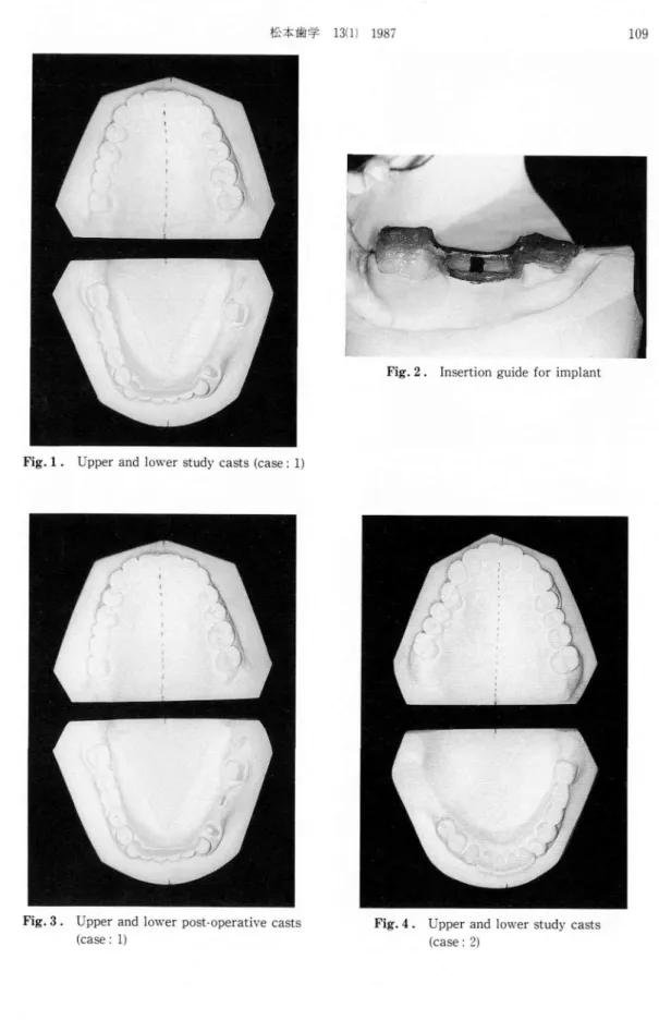
Case 1 : The patient is a 39-year-old female and has a [56- middle-defect (Fig. 1). Fig. 2 shows
the implant-insertion-guide. We are able to insert a 12 rnm Shape Memory Implant in the midddle
part of F4-and Fi7-. Fig. 3 shows its post-operative cast.
Case 2 : The patient is a 48-year-old female and has a -761 defect (Fig. 4). A 12 mm Shape Memory Implant was inserted into - 71 (Fig. 5).
2. Designing of the parallel casts
For each case, we drew accurate parallel casts on the basis of the occlusal plane of the lower jaw. The way of designing is the same as in the last reporti) : we positioned perpendicularly the back plane of the upper jaw cast to the medium line of the plate of the upper jaw or basic plane (occlusal
plane of Iower jaw). After making the upper and lower jaw casts occlude properly, we formed an
identical plane between the back plane of the lower jaw cast and. the back plane of the upper jaw
3. Method
As Fig. 6 shows, we photographed from three defferent directions to measure the efficiency of the guide.
(1) From the occlusal direction :
We made life-size photographs of the upper and lower parallel casts from the occlusal direction
with DSC-618-A PHOTOPET (manufactured by Dainihon Screen Co.), and designed the
occlusogram2'3). The occlusogram in the standard life-size photograph was taken of a parallel cast from the occlusal direction. The photographing condition was : iris 32, shutter speed 1 sec. Next,
each occlusogram was traced on the tracing paper (Fig. 7). We superimposed them, and compared
the implant-inserting position which was seen from the occlusal plane side and the position which was inserted practically, and also measured the positional relationship with the opposite tooth. (2) From the buccal direction :
Next we placed the guide in the right position on the casts and photographed it from the buccal direction. The photographing position was on the extended line of the implant-inserting position and it was perpendicular to the alveolar ridge line of the jaw banks. According to this photograph the mesio-distal palanting direction of the implant was measured from the buccal side.
(3) From the distal direction :
Lastly we cut the post-operative cast at the distal part of the implant-inserting position, which
is perpendicular to the alveolar ridge line. We then placed the guide and photographed from the
distal direction. According to this photograph the buccal planting direction was measured from of
ifAN tN de # 13i l) 1987
Fig. 1 . Upper and lower study casts (case:1)
109
Fig.2. Insertion guide for implant
Fig.3. Upper and
(case : 1)
lower post-operative casts Fig.4. Upper and (case : 2)
110
Murakami
,et al I Preparations foFig.5.
Upper and lower
casts (case: 2)
post-operaUve
B"...
r Endosseous Implants. Part L)
-t-.
D
' ' , ' Fig.6.@
o
krx
k
cutting iineThree photographing directions for
measuring the efficiency of the guide (O:
occlusal, B : buccal, D : dista] direction)
- ss.,., :
7
r
t y Åqf
I
1
,
---.---L...-"---
----1
ftx
ny . ' r ' l 1 ' 1 1 , 1 1 ' t 1. I ' 1 1 /@
!
Fig. 7 :if}Jlscva\ 13(1) 1987 111
Results
We tried to measure the following two cases by using the above method.
Case 1 : Fig. 8 shows that we superimposed the occlusogram tracing of the post-operative cast over one of the study cast.
The red part shows the bottom position of the implant-head; which was decided by using the
study cast before the operation. The blue part shows the bottom position of the implant-head which
was inserted practically. According to this figure we found that the practical implant-inserted
position was almost the same as the pre-operative decided position.
Fig. 9 shows that we superimposed the tracing of the post-operative cast upon one of the opposite tooth occlusogram.
From this figure we judged that the positional relationship between the implant-head and the opposite tooth was excellent.
Fig. 10 shows that we set up the guide on the post-operative cast correctly and photographed
it from the buccal direction. SA : The angle is made by the implant-head inclination of pre-and
post-operation. According to this figure we found that the mesio-distal planting direction inclined
about 4" mesially from the position decided before the operation. Fig. 11 shows that we cut the
post-operative cast at the distal part of the implant-head to be perpendicular to the alveolar ridge line, and photographed it from the distal direction. DA : The angle is made by the planting direction by pre-and post-overative implant-head. This figure indicates that the buccal planting direction inclined about 1.5" buccally from the pre-operative position.
Case 2: Same as case 1, Fig. 12 shows that we superimposed the occlusogram tracing of the
post-operative cast over one of the study cast. The red part shows the position of the implant-head on the study cast, which was decided before operation, and the blue part shows the bottom position of the jmplant-head which was inserted actually. From this tracing, we recognized the result that the position in which the implant was actually inserted displaced about 1 mm distally and about O.3
mm buccally compared with the pre-operative position.
Fig. 13 shows that we superimposed the occlusogram tracing for the post-operative cast over
one of the opposite teeth. According to this tracing, in relation to the opposite tooth, inserted implant-head was displaced slightly distal-buccally from the pre-operative decided position but as it was close to the central fossa of the opposite tooth, there was no clinical problem. Fig. 14 shows
that we photographed the post-operative cast with a guide from the buccal direction. We can see
that the planting direction of the implant-head inclined about 4.50 mesially from the pre-operative decided direction. Fig. 15 shows that we photographed from the distal direction.
We can see that the planting direction of the implant-head inclined about 3e buccally from the pre-operative position.
Discussion
As above, we summarized how we measured the efficiency of the guide and tried to measure
it ourselves by choosing two out of the recent implanting cases.
To sum up the results of the two measurements, the bottom of the implant-head was displaced about 1 mm at the maximum mesio-distally and about O.3 mm bucally. The planting direction
inclined about 4.5" at the maximum mesio-distally and about 3' buccally.
112 .Murakami,`'! a! IÅrreparations t'or I"lndosse{]us I[np]an(s. l'urt L)
t
?
x
ny . r r, l l , , ; l t 1 1 1 F r l , , --t---, a@
/
--- -- 'r --- ' t ---Åqz
4 5s , tk
1
1
Figr. S . S. ul)(;i'in)posins.r thcs traeinkr t)1' the lewt•r
sttidy c;Å}sl hv(,r post-tu)erntivt, c.nsl (case / 1)
Fig. 10 . Ph"t"gr"phin."
kTuidt' fi'o]ii thv
SA
thu implant•head with thu buccal direeti"n ccitst•/ 1)
Figr. 9. Suptii'in]p"sing tht• 1)i,gt-(4)er:Ltivv
t,I' iniplant-he;tcl nver traci:ik+ (Ff teelh tcns(•/ l)
p"sllleM
opl)osite
Fig. 11 . 1'holcikTrnphing the iTup]ntu hencl "'ith
guid{• t'r(}m tht• dist[tl direcii,)n {c;tehe/ b
thc'
---
, 1 l t , li.y
T1 1`
8
PAL ty?
2l
Fikr. 12 . Sul)vT'iT]]I)f,si[lg, CllSt d leX'UI' 1)-Sttht• trucing {)t' lower studv
•c,perut]vv c:tst (east,1 U) -rsS. Figr. 14 . }'11{,togri'iiphii)gr guiclv h',,n] the Åí
SA
D'get'the implunt-hc•ud with tht'
bucc;tl dirc;ctien ce"s(•/ 1!•`]
Figr. 1:l . Svp{'ril)IT)"7.illsl lht' 1){,bl-el)c-'uttive
"f inu)lttnt-head oyer trncing "i'
t(ieth (case / 1.')
i)osil l, -n
[,PI):,Sltv
Fig. 1,F, . l'h(,t`)gvuvhinyr the in)plunl-tiend "'ith
guidv 1'roni {hL' disutl dirtx'ti"n tc:tse / !b
ifEigut{I}k 13(1) 1987 113
decided on the study cast before the operation. Therefore, without a stardard, these is a possibility of having even more change. Even using the standard, it is difficult to establish the proper occlusal relationship of superstructures. If the superstructure is fixed without inserting the implant with proper position and direction, the implant body may be given an unsuitable divided force, causing resorption of the bone around it, and also movement of the implant. So the implant must be inserted in as possible to the position and the direction as closly which was decided on the study cast. In
addition, the force from outside-mainly the bite force- must be accepted on the extended axis which links the bone, the implant, the superstructure and the opposite tooth. To achieve this
insertion perfectly, an effective insertion induced guide is needed.
Although a few guides`'5) have been designed, they are mainly only trial guides, and do not, like the one the author designed6} induce the position and the direction of the bar directly when the
channel is drilled.
The author believes that the direction of the bar is vital to the setting up of the guide in the oral cavity when the channel is drilled.
The method we reported this time is considered to be extremely simple and effective in proving
the efficiency of this guide.
The special capabilities of the guide include the following :
(1) The inducement of the implant-inserting position and direction at the time when the channel is
drilled.
(2) The removal of the tongue at the time when the channel is drilled. (3) The removal of the lingual gingival flap.
It is useful for the above matters. However, one fault of the guide is that the implant-planting position and direction are easily changed buccally. Fortunately we saw only extremely small change
in this area.
Conclusion
To examine the method of measuring the efficiency of the implant insertion guide, we choose
two cases out of the recent implantings, photographed them from three directions (occlusal, buccal,
distal), compared, by the use of occlusogram, the pre-operative implant-inserting position and
direction on the study cast, with achieved ones on the post-operative cast, and gained the following
results.
1) As a method of measuring the efficiency of the implant insertion guide, having examined the study cast occlusally and the post-operative cast with the guide from three directions (occlusal, buccal, distal), our method is considered to be suitable.
2) The implant-inserting position changed about 1mm at the maximum mesio-distally and
about O.3 mm buccal-lingually.
3) The implant-planting direction inclined about 4.5e at the maximum mesio-distally and about
3' buccal-lingually.
4) Although a little change of both the implant-insening position and direction was recognized,
it was clinically irrelevant.
This insertion guide can be considered to be effective.
References
114 Murakami, et al : Preparations for Endosseous Implants. Part 2
endosseous implants-Observation of endosseous implants on the dental casts. Matsumoto Shigaku, 11 : 270-276. (in Japanese)
2) Deguchi, T. and Teramachi, K. (1982) Introduction of occlusogram in treatment planning. J.J. Orth•
odont. 41 : 283-290. (in Japanese)
3 ) Teramachi, K. and Deguchi, T. (1983) The application of the occlusogram in Japanese -A drawing of
maxillary ideal arch. J. J. Orthodont. 43 : 53-59. (in Japanese)
4 ) Yukawa, S. (1986) Development of trial guide for Bioceram implant in plate type and its employment.
J. O. I. R. 7: 19-24. (in Japanese)
5 ) Sano, K., Otori, M., Imanishi, H. and Hara, K. (1986) I. T. I. implant ni motiiru sitekigaido ni tuiteno itikousastu. JSOI 16th abstract, 33. (in Japanese)
6) Yoshida, K., Murakami, H., Kamiya, M., Fukuyo, S. and Hashimoto, K. (1986) Kotunai inpuranto no mainyuu ni kansuru gaidoni tuite. JSOI 16th abstract, 33. (in Japanese)