平成 24 年度 修士論文
Structural Characteristics of Groups of Traditional Wooden Houses in South Nias, Indonesia
指導教員 花里利一 教授
三重大学大学院工学研究科
建築学専攻
花里紗知穂
Structural Characteristics of groups of traditional wooden houses
in South Nias, Indonesia
Contents
Chapter 1 Introduction ··· 3
1.1 Scope ··· 3
1.2 Background ··· 3
1.2.1 Description of Nias Island ··· 3
1.2.2 Damages caused by the past Earthquakes ··· 7
1.3 Purpose ··· 9
1.4 Past Studies ··· 9
Chapter 2 Microtremor measurement ··· 13
2.1 Introduction ··· 13
2.2 Omo sebua ··· 19
2.3 Omo hada ··· 27
2.4 Concluding Remarks ··· 33
Chapter 3 Survey of Structure and Deterioration ··· 34
3.1 Introduction ··· 34
3.2 Results of Survey ··· 34
3.2.1 Survey of Deterioration ··· 34
3.2.2 Survey of Structure ··· 36
3.3 Concluding Remarks ··· 42
Chapter 4 Monitoring of Temperature and Humidity ··· 44
4.1 Introduction ··· 44
4.2 Result of Monitoring ··· 44
4.3 Concluding Remarks ··· 47
Chapter 5 Material Tests of Timber mambers··· 48
5.1 Introduction ··· 48
5.2 Compression Test of Wood ··· 48
5.2.1 Introduction ··· 48
5.2.2 Test Results ··· 49
5.3 Partial Compression Test of Wood ··· 52
5.3.1 Introduction ··· 52
5.3.2 Test Results ··· 54
5.4 Lateral Compression Test of Wood ··· 57
5.4.1 Introduction ··· 57
5.4.2 Test Results ··· 58
5.5 Concluding Remarks ··· 61
Chapter 6 Structural Analysis ··· 62
6.1 Introduction ··· 62
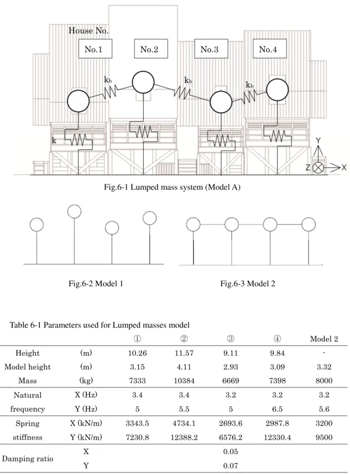
6.2 Coupling Effect ··· 62
6.2.1 Analysis Model ··· 62
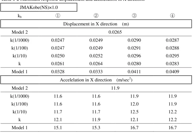
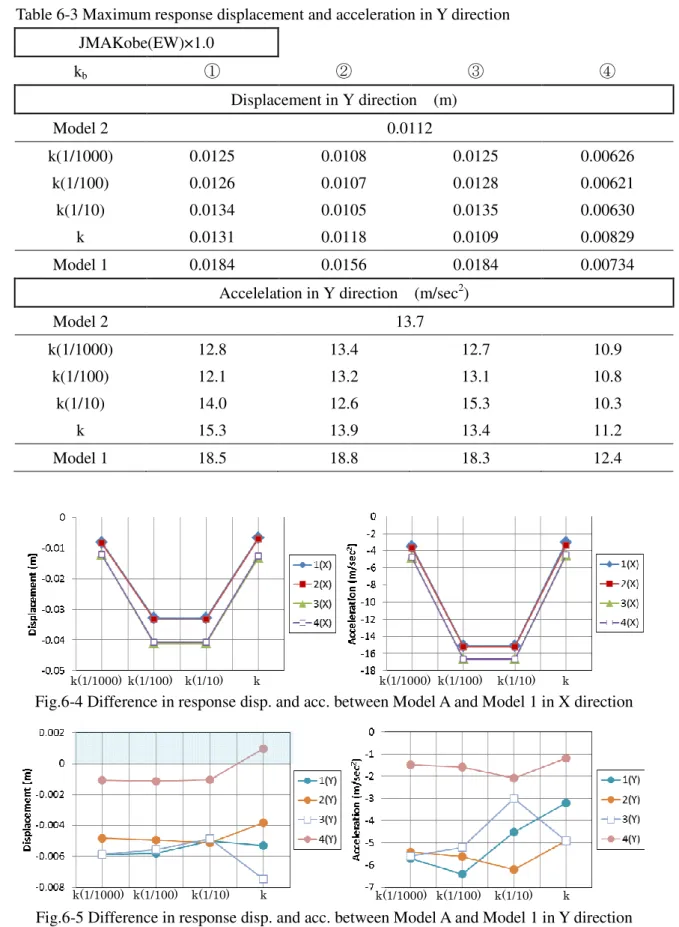
6.2.2 Results of analysis ··· 64
6.3 Collapsing Process Simulation ··· 67
6.3.1 Analysis Model ··· 67
6.3.2 Results of Analysis ··· 69
6.4 Concluding Remarks ··· 70
Chapter 7 Conclusion ··· 71
7.1 Summary of the Study ··· 71
7.2 Future Studies ··· 72
Acknowledgement ··· 73
References··· 74
Appendix
The drawing of omohada (house No.2)
(floor plan, cross section, and expansion plan) ··· 1
Chapter 1 Introduction
1.1 Scope
Indonesia consists of many islands and is a multiracial country. Each ethnic group has their own type of traditional wooden houses. Among them, we focus on the village of Bawomataluo in South Nias, Indonesia. Most of the traditional timber houses in South Nias have survived against the past large earthquakes in such seismic areas. In the present study, the structural characteristics of traditional wooden houses in South Nias were studied.
We conducted structural survey in the village of Bawomataluo in South Nias. In the present survey, micro-tremor measurements were carried out. As results of micro-tremor measurements, the fundamental characteristics of the traditional wooden house were evaluated. However, we found that some timbers were so deteriorated and damaged seriously by termite. These damages might have reduced the original seismic resistance. The climate monitoring was performed to study the effect of temperature and humidity on deterioration of timbers.
As no nails are used to construct the traditional houses, the joints were categorized into four types. Material tests of timbers used for structure were also conducted to examine the strength.
With these fundamental characteristics, earthquake response analyses were performed. The coupling effect of
omohada (houses lined in a row) was indicated by the analysis. Furtherstructural analysis would be needed to study the dynamic behaviors of traditional houses.
1.2 Background
1.2.1 Description of Nias Island
[1][6][13]Nias Island is located to the west of Sumatra Island, shown in Fig.1-2. There are approximately 700,000 people in Nias Island. Although they have dry and rainy seasons, it rains frequently particularly in the center and the north of Nias. The temperature ranges between average day (32
℃) and night (22
℃).
The architectural style of traditional wooden house is different among North part, central part, and South part (see Photo.1-1
~1-3). The traditional style in North Nias has elliptical shape of floor plan, standing independently. On the other hand, the traditional style in South Nias has rectangular plan, standing side by side. In central Nias, the traditional house is middle type between North type and South type.
A lot of trading vessels came to Nias Island at age of discovery. The main trading port was Gunungsitoli at North Nias, while many pirates came to South Nias because it was easy to hide around Telukdalam as second trading port. It can be noticed that the shape of the traditional house is similar to ships. A person who lives in Bawomataluo said that the shape of the traditional house arose from the ships of pirates when a lot of pirates came to Telukdalam.
Approximately 90 percent of Indonesian people are Muslim, while about 10 percent are
Christian. However, they had been native religion with customs of head hunting in the past time, so that the village should be at high place to be defended against other settlement. The village of Bawomataluo is on the top of the hill about 1.3 feet high from sea level. There are only three ways to go up the village with long stone steps. There is a stone stage called jumping stone which is approximately 2 meter in height. A man who jumped over the jumping stone could become a warrior at that time. The jumping stone is performed at traditional ceremonies and at a special accasion reguested by the tourists, nowadays (see Photo.1-5). There is a traditional dance called Lompat Batu (=war dance), which represent heroic attitude facing the enemies as the expression of glory in the war field.
The megalith culture had been developed in South Nias. There are many megaliths still now called
daro-daro (see Photo.1-7),being shaped rectangular or circular benches or tables.
The daro-daro is placed in front of water drainage, showing the rank of house owner. It is the physical reminder of past feasts of merit and lasting memorial to those who hosted them.
The village of
Bawomataluo was constructed between 1863 and 1878 by people whoescaped from the old village of
Orahili after its destruction by Dutch troops. Omosebua alsobuilt that period in the middle of the village.
On both side of the central paved line called ewali, the space is striated by crosswise paths leading to the house. This semi-public area can be classified into two socially significant zones.
The area under the eaves is a private area used mainly by woman for domestic chores.
In front of the area, both side of the street, there is water drainage called
elea slightly slopedtowards the end of village (see Photo.1-8).
Fig.1-1 Map of Indonesia
Fig.1-2 Map of Nias Island (source: HIC smatra, OCHA )
Nias IslandPhoto.1-1 Traditional house in North Nias Photo.1-2 Traditional houses in South Nias
Photo.1-3 Traditional house in Central Nias (source: Sato.K) Photo.1-4 Assembly house
①
①
①
①
②
②
②
② ③ ③ ③ ③ ④ ④ ④ ④
①: Omosebua
②: Omobale (Assembly house)
③: Jumping stone
④: omohada (to be studied)
Photo.1-5 Performance of Jumping stone Photo.1-6 Omosebua and ewali gorahua
Photo.1-7 daro-daro Photo.1-8 Open space in front of the house
1.2.2 Damages caused by the past Earthquakes
On December 26, 2004, a great earthquake occurred close to Sumatra. Tsunami caused by the earthquake attacked 12 countries. The damages forced people who live in Nias to live in tents or other temporary housing.
On March 28, 2005, another major earthquake occurred near the Nias Island shown in Fig.1-4. As a result, approximately 900 people dead and 70000 houses damaged or destroyed by the earthquake. More than 400 people were dead around the Gunung sitoli (: main city of North Nias), and 50 people were dead in Teluk dalam (: main city of South Nias). Most of masonry houses completely collapsed, which injured many people. In contrast, the traditional wooden houses in South Nias did not completely collapse by the earthquake. Those houses were damaged only the roof-frame particularly in the village of Bawogosari and Hilisimaetano. Some traditional houses leaned to front, being supported by temporary members, shown in Photo.1-9.
In consequence, it could be considered that the traditional wooden houses have seismic
consideration. The interesting point is why the traditional houses could survive against great
earthquakes.
Photo.1-9 Traditional houses damaged by earthquakes leaned to front
1.3 Purpose
It can be said that there are many cultural things worth preserving in South Nias, being maintained by people themselves. Although there are institutions to conserve cultural assets its self in Indonesia, no institutions have been organized to conserve the group of traditional buildings. The scope of the present research is to develop institutions organized for conservation of those groups as an international cooperation research with Indonesian experts.
In addition, the traditional houses in South Nias have survived against past earthquakes, indicating seismic resistant capacity. The purpose of this study is to clarify the structural characteristics and to evaluate the seismic safety of traditional wooden houses.
1.4 Past Studies
K.Andou and K.Inoue et.al reported the traditional wooden house in South Nias from a cultural point of view. Floor plan, cross section, and elevation of both of omosebua and omohada were drawn in detail by them.
The social structure and settlement pattern of South Nias are studied by them. There were used to be four social classes in traditional society of South Nias as siule (noble), ele (leader of native religion),
ono mbanua (general people) and sawuyu (slave). The settlement is basicallyplaced high level providing the area, which composed of an Assembly square, an Assembly house, houses, public bath, a Church, a Jumping stone, and public water place. The main road is widen at the center of the settlement for Assembly square, which have a stone called “fuso
newali” as a navel of village. The houses are ranged both side of main road, which has differentsize depend on the social class. In particular,
Omosebua (chief’s house) is remarkably large,which is also used for some ceremonies or other public things. The assembly house placed at the center of village is a place for important meeting, which is usually used as community space for men. K.Andou and K.Inoue considered that such occlusive settlement pattern with definite core as this come from custom of head hunting to defend against other settlement, indicating the stratified society of Nias.
They indicated the basic consideration of spaces (see Fig.1-5) that it goes more private space
one after another from main street to back of a house (in order from the main street : front
garden, stylobate, space under the eaves, dwelling, cattle shed , and kitchen garden) . The
dwelling is divided into front room and back room. Front room is used for customers or
bedroom for men as common space and back room is used for cooking, taking a meal, and
bedroom for women as private room. There is tiered space (which called
Bato, Danedane)where people spend their time freely seeing the main street through the opening. Nowadays,
most of all traditional wooden houses are extended to back space for removing the kitchen.
On construction method of traditional wooden houses in Bawomataluo, they presented that the traditional house can be divided into three parts; under floor space, living space, and roof frame.
Nuki and Kashira-nukisupported under-floor frame rigidly with braces. At the living space, beams and walls of front and back connected two parts of thick walls in ridge direction as a BOX. The roof frame structure is relatively light, consisting of braces in span direction. The beams connect three triangular frames of roof structure. Two openings at the roof, which can be adjusted the opening level, are so effective in getting light and ventilation. [2,3, and 4]
Fig.1-5 The basic consideration of spaces
Fig.1-6 Three parts of traditional wooden house
M.Sato reported the process of transformation of traditional wooden houses in Nias. Many houses are roofed with GI sheets or other steel sheet instead of traditional Sago leaves. These new material could keep good condition longer than Sago leaves without rain leaking through the roof, so that a number of people changed roof material from Sago leaves to GI sheets.
However, those materials raised temperature of the space in the roof because of high thermal conductivity. As a result, some people started to use the space under the floor, making concrete walls with concrete blocks between columns instead of the braces. Thus the space under the floor becomes living space, using several kinds of door including glasses.
As living space was changed from on the floor to under floor, some people build a low house of one story instead of traditional wooden house. Some people built houses of two stories with balcony to make more floor space for bedroom.
Sato. M also presented the ornament and sculptured parts of a building in Indonesia.
He considered that the traditional style would disappear when people change their life style by changing roof material from Sago leaves to GI sheets. He was afraid that yang generation should go outside of the village for long time to earn money in order to live in their traditional house comfortably.[5]
Two opening Roof structure
Understructure Living space
K.Sato studied wooden houses in Southeast Asia and Oceania from the point of prototype and development. He categorized those houses by 7 points; 1.The name of house, 2.Cross beam or beam structure, 3.Elevated floor style, 4.Basement, 5.Expansion, 6.Roof construction and 7.Mixed style. The prototype of the short pillar style is elevated floor supported by four short pillars which arranged in a square. Short pillar – roof style is the first type which has only roof.
It developed as Short pillar – wall style which has side walls and posts supporting the ridge
directly from the floor. The style of traditional wooden house in South Nias is included in the
category of Short pillar – wall style with gable roof. The granary of Toraja-Sa’dan (Serebes), the
house of Toraja-Sa’dan, the house of Lio (Flores), and the long house of Dayaks (Borneo) are in
same category.[7]
Chapter 2 Microtremor measurement
2.1 Introduction
We conducted micro-tremor measurement at both Omosebua (; a headman lived in formerly) and Omohada (; common people live here). (see Photo.2-3 and 2-4) Those heritage structures have two kinds of roof materials; GI sheets and sago leaves.
Measurements of micro-tremor were carried out by using 6 micro-tremor sensors, shown as Fig.5. Sampling duration was 60 seconds for each record with sampling frequency of 100 Hz using a portable monitoring equipment of SPC-51A (Tokyo Sokushin Co., Ltd.). We carried out the measurement in 18 cases including manpower excitation tests in both span and ridge directions (see Table 2-1). Fig.2-1
~2-14 show arrangement of the sensors for each measurement case. One sensor was placed on the base, while the other sensors were arranged on the structure for calculation of transfer function to evaluate the natural frequency and the vibration mode.
Photo.2-1 Sensors Photo.2-2 micro tremor measurement
Photo.2-3 Omohada
Photo.2-4 Omosebua
Fig.2-1 Arrangement for case 1-1
Fig.2-2 Arrangement for case 1-1’
X X X X Y
YY Y
X X X X YY Y
Y
X X X X Y
YY Y CCCCh1 h1 h1 h1 CCCCh6 h6 h6 h6
CCCCh5 h5 h5 h5
CCCCh4 h4 h4 h4
CCCCh3 h3 h3 h3 CCCCh2 h2 h2 h2 CCCCh6 h6 h6 h6
CCCCh2 h2 h2 h2 CCCCh4 h4 h4 h4 CCCCh5 h5 h5 h5 CCCCh3 h3 h3 h3
CCCCh1 h1 h1 h1
CCCCh2 h2 h2 h2 CCCCh3 h3 h3 h3 CCCCh4 h4 h4 h4 CCCCh5 h5 h5 h5
CCCCh6 h6 h6 h6
CCCCh1 h1 h1 h1
Fig.2-4 Arrangement for case 1-3, case 3-2
Fig.2-5 Arrangement for case 1-2
Fig.2-6 Arrangement for case 1-2’
X X X X Y YY
Y CCCCh1 h1 h1 h1 CCCCh6 h6 h6 h6
CCCCh5 h5 h5 h5
CCCCh4 h4 h4 h4
CCCCh3 h3 h3 h3 CCCCh2 h2 h2 h2
X X X X Y
YY Y
CCCCh2 h2 h2 h2
CCCCh3 h3 h3 h3 CCCCh4 h4 h4 h4 CCCCh5 h5 h5 h5
CCCCh6 h6 h6 h6
CCCCh1 h1 h1 h1
X X X X Y
YY Y
CCCCh3 h3 h3 h3 CCCCh4 h4 h4 h4 CCCCh5 h5 h5 h5
CCCCh6 h6 h6 h6
CCCCh1 h1 h1 h1
CCCCh2 h2 h2 h2
Fig.2-7 Arrangement for case 1-6
Fig.2-8 Arrangement for case 1-7
X X X X Y
YY Y
CCCCh2 h2 h2 h2
CCCCh3 h3 h3 h3 CCCCh4 h4 h4 h4 CCCCh5 h5 h5 CCCCh6 h5 h6 h6 h6 CCCCh1 h1 h1 h1
X X X X YY Y
Y
X X X
X YY Y Y CCCCh2 h2 h2 h2 CCCCh3 h3 h3 h3 CCCCh4 h4 h4 h4 CCCCh5 h5 h5 h5
CCCCh6 h6 h6 h6 CCCCh1 h1 h1 h1
CCCCh5 h5 h5 CCCCh6 h5 h6 h6 h6
Fig.2-10 Arrangement for case 2-3, case 2-3’
Fig.2-11 Arrangement for case 2-1
Fig.2-12 Arrangement for case 2-2
Fig.2-13 Arrangement for case 2-5
CCCCh2 h2 h2 h2 CCCCh3 h3 h3 h3 CCCCh4 h4 h4 h4 CCCCh5 h5 h5 h5
CCCCh6 h6 h6 h6 CCCCh1 h1 h1 h1
CCCCh2 h2 h2 h2 CCCCh3 h3 h3 h3 CCCCh4 h4 h4 h4 CCCCh5 h5 h5 h5
CCCCh6 h6 h6 h6 CCCCh1 h1 h1 h1
X X
X X Y YY Y CCCCh2 h2 h2 h2
CCCCh3 h3 h3 h3
CCCCh4 h4 h4 h4 CCCCh5 h5 h5 h5
CCCCh6 h6 h6 h6 CCCCh1 h1 h1 h1
CCCCh2 h2 h2 h2 CCCCh3 h3 h3 h3 CCCCh4 h4 h4 h4 CCCCh5 h5 h5 h5
CCCCh6 h6 h6 h6
CCCCh1 h1 h1 h1
Fig.2-14 Arrangement for case 1-5
Table 2-1 Series of micro tremor measurements
case No. Sensor point and direction
omo sebua
case1-1 Span direction
case1-1' Span direction (in-plane on the floor) case1-4 Span direction for vibration mode case3-1 Span direction for manpower excitation case1-3 Ridge direction for vibration mode case3-2 Ridge direction for manpower excitation case1-2 Ridge direction (in-plane without basement)
cese1-2' Ridge direction (in-plane)
case1-6 Beam level for orbit
case1-7 Span direction (in-plane on the beam level)
case1-5 ground
omo hada
case2-1 Span direction on the floor level case2-2 Ridge direction on the floor level case2-3 Span direction on the beam level case2-3' Span direction for manpower excitation case2-4 Ridge direction on the beam level case2-4' Ridge direction for manpower excitation case2-5 For vibration mode and orbit
CCCCh2 h2 h2 h2
CCCCh3 h3 h3 h3 CCCCh1 h1 h1 h1
XX XX YYY
Y ZZZZ
2.2 Omo sebua
Transfer function calculated from the micro tremor records revealed that the natural frequency was 2.0 Hz and 3.1 Hz for X direction (=span direction) and for Y direction (=ridge direction), respectably at Omosebua. (see Fig.2-15
~2-19)
The amplitude shown in Fig.2-20 is average of the measurement of case1-4 and 1-3.
Traditional houses structurally consist of three parts; roof structure, middle structure for living space and understructure. The under-structure is so stiff in both directions because of thick braces, while there was a difference in stiffness at middle structure (living space) between span and ridge directions. The vibration mode in span direction indicated that the large displacement was caused in span direction at the middle structure, so that this layer is weak against earthquake loads in span direction. The large displacement might be caused by different shear wall quantity between span and ridge directions.
Fig.2-22 and 2-23 show the vibration mode in horizontal in-plane of floor level and beam level calculated from the amplitude of the transfer function measured in case1-1’, 1-2’, and 1-7.
It seems that the large displacement at middle structure in Y direction (=ridge direction) is caused by thick walls. On the other hand, there are differences in vibration mode between floor level and roof level in X direction (=span direction). It can be considered that horizontal in-plane rigidity of the floor was insufficient. The vibration mode of beam level was affected by walls in span direction at backside of omosebua. However, further study should be needed to evaluate the differences between floor level and roof level.
The damping factor was calculated from the free vibration test. Those tests showed the
damping factor of 2.5% and 2.1% in span direction and in ridge direction, respectively. Fig.2-21
shows free vibration waveforms produced by man power. It can be considered that the damping
factor is slightly lower than that of Japanese traditional wooden houses.
Fig.2-15 Transfer Function measured in case 1-4 (span direction)
20ES 15
E
コ
主
10旬
ω!5 5
ト帽ー‑
。 。
1 2 3 4 5 6Frequency(Hz) 7 8 9 10
120
八
| ー紬/1叩eam/乱~
E30
。 。
1 2 3 4 5 6 1 8 9 10 Frequency(Hz)2
∞
5 │ 一一
5叫
lch{RoofjGL)│宮150 z
コ
E1∞
。 。
1 2 3 4 5 6 7 8 9 10 Frequency(Hz)2
凹
z e 宮z150 '
=
:'"1∞
L@ u園.
,
!; 50
ト何ーーB
。 。
1 2 3 4 5 6 7 8 9 10 Frequency(Hz)Fig.2-16 Transfer Function measured in case 1-3 (ridge direction) 2 5
.s
=
5u s z2 0
│ 一 一 2 c h j 1 c h
(1FI o o r j G L )
1
. .
,
....
? :
。 。 1 2 3 4 5 6
78
91 0 F r e q u e n c y ( H z )
4 U
主 己
M g sヌ O
E 2 2 1 0 0
。 。 1 2 3 4 5 6
78
91 0 F r e q u e n c y ( H z )
IU
0;ε~ ::
6 0 ハ 一 」一 一 5 c h j l c h( R o o
f/G L )
ー
=
s5 0
協
4 0
‑Z5
3 ? の 0 1 0
。 。 1 2 3 4
JG
78
91 0 F r e q u e n c y ( H z )
8 0
S z
Z 2 U6 O
E 2 0
。 。 1 2 3 4 5 6
78
91 0
F r e q u e n c y ( H z )
Fig.2-17 Transfer Function measured in case 1-1’ (span direction)
50
5
ー
4・
4UJ
│‑ ‑2ch/1ch (Floo府L)
│3
30』 ・ と
"ZOE
~ 10
。 。
1 2ヨ
4 5 6 7 8 9 10 Frequency(Hz)50
6
40 │‑ ‑3ch/1ch {Floor/GL}司
5 、
Fd・ ・
30u.
書
20E
~ 10
。 。
1 z 3 4 5 6 7 8 9 10 Frequency(Hz)フ
0E 6 15
│ 一一
4ch/1ch(FloorjGL)I
‑噌 ーd '
E ヨ
主
1U司
2
副U・
3 5。 。
1 1ヨ
4 b b / t三 ':1 10 Frequency(Hz)7 E6
吉
z=
5L&. 4
. ロ 包
3c 2
BR=
,
1。 。
1 z 3 4 5 6 7 8 9 10 Frequency(Hz)140
EE u 120
一 」
‑ ‑bch/1Ch( IOp/GL) 100ヨ 80
L L
:U 60 t世;;
c :
110 E10。 。
1 2 3 4 5 6 7 8 9 10 Frequency(Hz)Fig.2-18 Transfer Function measured in case 1-2’ (ridge direction)
205 、
E,
15r 、
p、 │ 一一
lCh/2ch(Floor/GL)│L2 』 10 TqEZ ‑u 5
ト同』ー
。 。
1z
3 4 5 6 y 8 9 10 Frequency(Hz)lU
ぢ~
15│ ーー州 州
Floor/GL)│主
E 10司
副 =
。 。
1z
3 4 5 6 y 8 9 10 Frequency(Hz)3S
1Z 5ME 30 2S 呈20
τ 包
E 15 10戸開 5
。 。
1 2ヨ
4 5 6 7 8 9 10 Frequency(Hz)SO
a
110 1‑ ‑SCh/2ch (B凹 m/GL)I
12 E30 U LL.
宰
E‑20直
10。 。
1 2 3 4 、J G 7 8 9 10 Frequency(Hz)~U
ぢ 1 5
25 /1一 」
‑ ‑Gch/2ch(Beam/GL) 520. . . .
1 ̲r;宮田 10 45= 5
。 。
1 2ヨ
4 5 6 7 8 9 10 Frequency(Hz)Fig.2-19 Transfer Function measured in case 1-7 (span direction)
80
5 、
E,
60│ 一一
1ch/2ch(Beam/GL)│也
=
40也
忽
‑
トE20
。 。
1 2 3 4 5 6 7 8 9 10 Frequency(Hz)100
!
80 │一 一拍
/2ch(Be;Jm/GL)tZ 560
LL
JL. 凶
! !
40E
~ 20
。 。
1 2 3 4 5 6 7 8 9 10 Frequency(Hz)120
1
51
∞
│一 一4
ch/2ch(Beam/GL)4Ed 80
主
ヨ60主
由
40 4伺: 20。 。
1 2 3 4 5 6 7 8 9 10 Frequency(Hz)LUU .g150
E
コ
也 100
匂』副
・ '
・‑550
。 。
3 ::¥ 4三 ?
6 7 R q 10 Frequency(Hz)200
品
50E S
主
100『
‑完
u: i i
50』E•
。 。
1 2 3 4 5 6 7 8 9 10 Frequency(Hz)Fig.2-20 Vibration mode of Ridge Direction
Fig.2-21 free vibration wave (upper: span direction / lower: ridge direction)
h=2.5%h=2.1%
Fig.2-22 Vibration mode of Span direction (2 Hz) (Upper: Floor level, Lower: Beam level )
Fig.2-23 Vibration mode of Ridge direction (3 Hz) (Left: Floor level, right: Beam level)
: Floor : Beam : Floor : Beam
2.3 Omo hada
Transfer function calculated from the micro tremor records showed that the natural frequency was 3.4 Hz in X direction (=span direction) at Omohada, shown in Figs.2-24, 2-25, and 2-28. On the other hand, the natural frequency in Y direction (=ridge direction) was not observed clearly, which could be considered 5
~5.5Hz, shown in Figs.2-26, 2-27, and 2-29. The significant difference could not be found in the natural frequency between the house roofed with GI sheet and the house roofed with Sago leaves.
The vibration mode for the first mode determined from the amplitude of the transfer function which measured at case 2-5 from the foundation to the measures points are presented in Fig.2-30. It should be noticed that the story drift at middle structure (living space) in span direction is larger than that in ridge direction, caused by stiffness of walls in ridge direction.
Additional sensors should be put on the roof frame to calculate vibration mode in more details for further study.
The damping factor was calculated from the free vibration test as 5
~6% and 7% for X direction and for Y direction, respectively. This record showed that the damping factor of omohada was high in comparison with that of omosebua. Fig.2-31 shows the free vibration waveforms produced by man power. The recorded waveform did not show the features of free vibration with damping particularly in ridge direction, therefore, it would need more survey to exactly evaluate the damping factor.
The groups of Omohada stand side by side, connected with one passage. It could be
considered that such connecting condition caused coupling effect that would be effective in
reduction of the structural response. The man power excitation tests were performed to verify
this effect on the dynamic performance. When the house No.
①was excited by manpower, the
house No.
④started to vibrate with its natural frequency, shown in Fig.2-32.
Fig.2-24 Transfer Function measured in case 2-3 (span direction)
Fig.2-26 Transfer Function measured in case 2-4 (Ridge direction)
Fig.2-27 Transfer Function measured in case 2-5 (Ridge direction)
Fig.2-28 Transfer Function measured in case 2-1 (Span direction)
3525
也 20 10
5
。 。
1 2 3 4 5 6 7 8 9 10Frequency(Hz) 40
5g s M 30
310
。 。
1 2 3 4 5 6 7 8 9 10 Frequency(Hz)25
. 5
5
Z 2M
20│‑ ‑4chj1ch (FloorjGL)│ 15
制』
主
51‑
05。 。
1 2 3 4 5 6 7 8 9 10 Frequency(Hz)40
5
Z 2M
30 1 22Z 2100。 。
1 2 3 4 5 6 7 8 9 10 Frequency(Hz)Fig.2-29 Transfer Function measured in case 2-2 (Ridge direction)
8
5Z 2 M 6
122Z 4 2
。 。
1 2 3 4 5 6 7 8 9 10 Frequency(Hz)20 52 埴Z 15
│ 一 一 →
3chj1帥 出
Ch川叩附(仔FF円
l加附o∞
or卯
L)│
E 5
。 。
1 2 3 4 5 6 7 8 9 10 Frequency(Hz)7
':4
1‑ZZZ 3 2 1
。 。
1 2 3 4 5 6 7 8 9 10 Frequency(Hz)20 53 抽Z 15
E 5
。 。
1 2 3 4 5 6 7 8 9 10 Frequency(Hz)Fig.2-30 Vibration mode of Omohada
Fig.2-31 Free vibration waveform (upper: span direction / lower: ridge direction)
Fig.2-32 Coupling effect of four houses
2.4 Concluding Remarks
The natural frequency in span direction was lower than that in ridge direction at both of
omosebua and omohada, indicating the structural stiffness in span direction is more flexiblethan that in ridge direction. It was considered that there is a difference in dynamic behaviors between two directions caused by braces at understructure, and roof structure, and walls at middle structure.
Although the fundamental characteristics peculiarity of omosebua were made clear from the micro tremor measurement, it would need more study to evaluate the seismic safety.
No.① No.② No.③ No.④
Chapter 3 Survey of Structure and Deterioration
3.1 Introduction
Nails were not used for construction of the traditional houses in Nias, therefore, the detail of joints are important for the structural analysis. We surveyed omosebua and omohada especially of joints to understand the detail. This survey was performed by using tape measure and laser range finder (see Photo.3-2).
In addition, deterioration and deformation of the timbers were inspected in
Omosebua inorder to discuss the restoration methods by NITTO (Tokyo Univ. of the Arts). The survey was performed as the followings; 1. Visual inspection, 2. Percussion tests using wooden hammer. 3.
Using Laser Marking Equipment to investigate a lean of frame or differential settlement
3.2 Results of Survey
3.2.1 Survey of Deterioration of Omosebua
1) Foundation/ Under the floor
It was very humid under the elevated floor, in particular, at the corner of northeast where was close to the next house. It was unclean condition because of scattered garbage. The foundation stones did not have cracks so that the stone cut out from natural stone, however, conspicuous differential settlement were obviously found.
Both columns and braces were seriously damaged by attack of termite. (see Photo.3-3) It seems that the timbers in the living space were already damaged by termite which came from the columns at under-floor. From this survey, 29 columns and 10 braces should be replaced because of serious damage by termite. Most of those timbers seem to be new members or second-used members, which made it difficult to identify the members originally used.
The maximum inclination of columns was 10/100, of while most of columns were inclined
4/100. The maximum differential settlement of columns was 13 cm. As the members under floor
are easy to be damaged by termite and decay, those timbers have been replaced with new
members quite frequently using conventional method (; dig around the target column
cornerstone, replace the column, and put the cornerstone back to the original position.). The
conventional method might cause remarkable differences in inclination and differential
settlement of each column.
Photo.3-1 Laser Marking Equipment Photo.3-2 Laser range finder
Photo.3-4 Distortion of living space floor Photo.3-3 Bite mark of termite and
laser light of Laser Marking Equipment 2) Space of living
Some of the side columns tilted toward inside, of which maximum inclination was 6/100.
Irregular settlement of floor line was also found as deterioration. The floor was not horizontally flat, but it was curved as the center was higher than the side end of the room in span direction.
There was 16 cm difference in height between the center and the end. This deformed floor was originally designed as the present traditional wooden houses were originated from ships. Harms by termite were found in the living space particularly at the back room.
3) Roof structure
The Nias offshore earthquake of 2005 caused damages to the roof frame and roofing material (cf. chapter1). The roof frames decayed in several places because of rain leaking from roof apertures caused by the earthquake. Harms by termite were also found at the roof frame.
(see Photo.3-5) It could be considered that the roof frames of traditional house were damaged by earthquake because of those deteriorations.
(Source: Leica Geosystems-Japan)
Photo.3-5 Harms by termite and roof frame 3.2.2 Survey of Structure
We observed the structure of both omosebua and omohada (In particular, the house which is roofed with Sago). Detail of joints and dimensions were recorded by this structural survey.
Although there are some differences in numbers or in dimensions of structural members between
omosebua and omohada, the construction method of both structures is basically thesame.
1) Connection between houses
Photo.3-6 shows the entrance which connects neighboring houses. The detail of these connections is important to assess interaction and coupling effect between houses (cf. chapter2).
The passage is supported by both sides of columns using wooden pegs (see Fig.3-1). Some traditional wooden houses have timbers connecting walls of neighboring houses above the passage (see Photo.3-7). On the other hand, there are only a few timbers to connect at the other side, which has only about 10 cm gap between houses, shown in Photo.3-8. Roofing materials are overlapped each other above the passage.
Photo.3-7 Above the passage
Fig.3-1 Joint of passage using wooden peg
2) Under the floor
Fig.3-2 shows the joint between a column and a horizontal member under the floor. The traditional houses have 4-row columns for span direction regardless of width of the house. Each column is connected with penetrating beam in span direction, of which ends are connected by
“kashiranuki” in ridge direction.
They have braces for both of span and ridge direction. The braces for span direction are penetrated by horizontal members, while the braces for ridge direction are only put on the horizontal members shown in Photo.3-10 and Photo.3-12. Front façade is characterized by thick braces which are connected each other at the base (see Photo.3-11). Photo.3-13 shows the understructure and column with penetrating beam, respectively.
Harms by termite were also found particularly at the lower part of the columns, shown in Photo.3-14.
Fig.3-2 The joint around the column
70 35 85
48
(mm)
210 150 195 35
160
33
65
17 30 110 Wood peg
Photo.3-9 Front façade Photo.3-10 Brace with penetrating member
Photo.3-11 Base of front brace Photo.3-12 Brace for ridge direction
Photo.3-13 Understructure Photo.3-14 Harms by termite
3) Living space
People who live in Bawomataruo often spend their time at the stage facing to the main street shown in Photo.3-15, which serving both for bench and storage space (see Photo.3-17). Flesh air can blow through the house because of the main lattice opening at the stage and other two opening at the roof, shown in Photo.3-15.
The living space is surrounded by thick walls shown in Fig.3-3. The wall consisted of wooden panels inserted into mortise at the crossbeam (see Fig.3-4). Those tenon are complicated configuration to make surface area larger, which would improve strength of embedment and friction force.
Two posts which directly support the ridge of a roof stand on the floor, being separated from the columns under the floor (see Photo.3-16).
Fig.3-4 Detail of thick wall
Thick wallPosts
(: directly support the ridge of a roof) Cross beam
Cross beam
mortise
Fig.3-3 Living space (source: M. Inoue,”Housing construction method in Nias”)
Photo.3-15 The stage at living space
Photo.3-16 Post stand on the floor Photo.3-17 Serving both for bench and storage
4) Roof frame
Omohada have various heights because of different number of timbers and different
dimensions. According to the past studies, some of the houses were damaged by the Sumatra earthquake in 2004 and Nias earthquake in 2005. However, those damages concentrated at roof structure.
Triangular frame consisted of struts with tenon in regular interval (see in Fig.3-5) were connected with beams. There were 20 braces only for span direction, shown in Photo.3-18 and Fig.3-6. The posts which directly support the ridge of a roof were connected with triangular frame using pin, shown in Photo.3-20.
Lattice opening
Opening at the roof
Spot of Braces
Fig.3-6 Spot of braces at roof structure
Photo.3-18 Detail of braces at roof structure Fig.3-5 Roof structure and triangular frame
(After: M. Inoue,
”Housing construction method in Nias”)
Photo.3-19 Inside roof frame Photo.3-20 Joint of post and
triangularframe
3.3 Concluding Remarks
In conclusion, joints used in the traditional wooden houses in South Nias can be categorized into 4 types from the present survey, shown in Table3-1.
Most joints can be categorized into joint No.1. There exist high rigid joints at lower part of the house, for example joint No.3 or No.4. It indicates the stability of the house.
On the other hand, we found tilting of the structures caused by the earthquakes or aging
deterioration with differential settlement and harms by termite. It could be considered that those
damages would reduce structural stability of the traditional houses.
Table3-1 Categories of joints
①Joint connected with notch
■
Under floor
Braces for ridge direction.
■
Living space
Joint between beams and crossbeams.
Upper part of the stage.
■
Roof frame
All beams connected with both side.
② Kashira-nuki
■
Under floor
Joint between columns and cross beams.
③
Penetrating beam with pin
■
Under floor
Joint between cross beams and under floor beams.
■
Living space
Lower part of the stage.
At the middle crossbeams.
④
Penetrating beam without pin
■
Under floor
Joint between columns and beams.
Some of the joint between cross beams
and under floor beams.
Chapter 4 Monitoring of Temperature and Humidity
4.1 Introduction
There are many houses roofed not only with Sago leaves but also with GI sheets in
Bawomataruo. To discuss how the roof materials affected the climate condition in the roofstructure, temperature and humidity monitoring was conducted. We installed hygrothermographs at two of the house of Sago leaves roof and of GI sheets roof to record temperature and humidity for half a year from Dec.12, 2011 to Jul.12, 2012
The monitoring had been carried out by using 2 sensors (LR5001, Hioki Co.). Both sensors were installed in the roof structure of houses roofed with Sago leaves and GI sheet (see Photo.4-1). Photo.4-3 shows the arrangement of the sensors.
Another monitoring to measure temperature and humidity of living space and under floor space was started on Dec.27, 2012. The data for three days were collected and analyzed. Two sensors were installed at living space and under floor space of the house roofed with Sago, shown in Photo.4-4.
4.2 Result of Monitoring
The monitoring records showed that the temperature and humidity of the house roofed with GI sheets varied more largely in a day (in 24 hours) than the house roofed with Sago leaves. The temperature inside GI sheets roof reached nearly 40
℃, being higher than that inside Sago roof, shown in Fig.4-1. On the other hand, there are no clear differences between rainy season and dry season.
Fig.4-3 and 4-4 show the result of monitoring for 2 days when other sensors were installed.
In comparison between the results of roof frame from Jan.1 to Jan.7, 2011 and results of living space and understructure from Jan.1 to Jan.7, 2012, the highest temperature was shown inside the roof frame. On the other hand, the humidity inside the roof frame was lowest among them.
The humidity of the space under the floor is relatively higher than that of living space,
indicating that humidity promote the deterioration of timbers.
Photo.4-2 Hygrothermograph Photo.4-1 Traditional houses in which sensors were installed
Photo.4-3 Arrangement of the sensors inside roof frame
Photo.4-4 Arrangement of the sensors (left: understructure, right: living space)
Fig.4-1 Result of monitoring inside the roof frame (S: Sago leaves, GI: GI sheet)
Fig.4-3 Comparison of three monitoring points for 2 days (Temperature)
Fig.4-4 Comparison of three monitoring points for 2 days (Humidity)
4.3 Concluding Remarks
The monitoring of temperature and humidity indicated that the deterioration of timbers was caused by high humidity recorded in both Sago roof and GI sheets roof. Furthermore, timbers under floor part are prone to deteriorate as the humidity was so high there.
Further study would be needed to understand the effect of large difference between high and
low humidity, observed in the GI sheet roof, on the deterioration of the wooden materials.
Chapter 5 Material Tests of Timber members
5.1 Introduction
The traditional wooden houses in Nias are constructed with local woods such as Afoa, Berua,
Manawadano, Siholi, and so on. However there have been no reports regarding tocharacteristics of local timber in Nias. Therefore, material mechanical tests of those woods were conducted to obtain fundamental mechanical properties of those wooden members used for the traditional wooden house in South Nias.
5.2 Compression Test of Wood
5.2.1 Introduction
We conducted compression test of wood materials (Berua, Manawadano, Afoa) actually used for structure of traditional houses in South Nias. The compressive strength and rigidity of these woods were evaluated by the tests.
In the present test, the test pieces are cut down in rectangular ones (25mm×25mm×75mm).
Three test specimens were made from the wooden members. Those specimens were compressed in the grain direction, shown in Table 5-1 and Fig.5-1.
Fig.5-1 Test specimen and the way of loading
a1 a2
h (75mm)
A (25mm) (25mm)
Table 5-1 Test specimen
a1 a2 A h V m ρ
mm mm mm2 mm cm3 g g/cm3
A-1 24 24.5 588 75.5 44.4 25 0.56
A-2 25 24.5 612.5 75 45.9 23.6 0.51
A-3 25 25 625 75 46.9 22.2 0.47
M-1 25 24.5 612.5 75.5 46.2 37.6 0.81
M-2 25 24 600 76 45.6 39 0.86
M-3 23 25 575 73 42.0 39.3 0.94
B-1 25 24 600 75 45 38.1 0.85
B-2 25 25 625 76 47.5 41.7 0.88
B-3 24 25 600 76 45.6 43.7 0.96
5.2.2 Test results
Compressive strength and displacement at the maximum strength of three kinds of woods were obtained (see Table5-2). The compressive strength of Nias timber is relatively higher than that of Japanese woods (see Table5-3). In particular,
Berua and Manawadano have largecompressive strength as 2 or 3 times strong as the Japanese one. Fig.5-2 describes Stress-strain relation. The rigidity of Manawadano and
Berua was close to that of the Japanese woods. (seeTable5-3)
Table 5-2 Result of test
compressive strength
displacement (max strength)
initial
stiffness stiffness
N/mm2 mm N/mm2 N/mm2
A-1 42.9 1.7 642.0 1605.0
A-2 41.6 1.8 775.5 2571.4
A-3 33.4 1.4 572.3 2840.0
Ave(Afoa) 39.3 1.6 663.3 2338.8
M-1 61.3 1.4 1540.8 5053.9
M-2 72.0 1.7 1931.7 10893.3
M-3 69.7 2.2 465.5 7363.5
Ave(Manawadano) 67.7 1.8 1312.7 7770.2
B-1 66.8 2.7 458.3 7250.0
B-2 70.3 1.4 1641.6 13619.2
B-3 52.8 1.8 1604.4 4222.2
Ave(Berua) 68.6 2.1 1050.0 10434.6
Table 5-3 The material strength standard of timber structural design criteria (AIJ)
[14]Standard strength of material Fc E0
Coniferous Tree
Ⅰclass Beimatsu 22.2 10000
Ⅱclass Hinoki 20.7 9000
Ⅲclass Karamatu 19.2 8000
Ⅳclass Sugi 17.7 7000
Broadleaf Tree
Ⅰclass Kashi 27.0 10000
Ⅱclass Keyaki, Nara 21.0 8000
Ⅲclass Lauan 21.0 7000
(N/mm2) (N/mm2)
(Afoa) (Manawadano)
(Berua)
Fig.5-2 Stress-strain relation
The upper part of A-1, M-2 and B-1 were smashed, on the other hand, the lower part of A-3 was compressed and splitted lengthwise. A-2 and M-3 showed shear failure behavior. The upper part of B-2 and M-1 embedded in the bottom. B-3 indicated the maximum load in a short time and cracked lengthwise because of knot the test specimen has. The condition of test pieces affected the failure mechanism.
Photo.5-2 Failure mode of Afoa (from the left: A-1, A-2, A-3))
Photo.5-3 Failure mode of Manawadano (from the left: M-1, M-2, M-3)
Photo.5-4 Failure mode of Berua (from the left: B-1, B-2, B-3)
5.3 Partial Compression Test of Wood
5.3.1 Introduction
We conducted partial compression test of wood materials (Berua, Manawadano, Afoa) used for structure of traditional houses in South Nias The partial compressive strength and embedding stiffness were measured by the test in accordance with the Manual of structural timber (published by Japan Housing and Wood Technology Center[15]).
The test specimens were cut down in rectangular ones (approximately 60mm×60mm×600mm). A total of three specimens were made from each wood, compressed partially in the direction perpendicular to the grain. The vertical load was applied through a plate of steel (10mm×100mm×300mm) . That was put in the center of the test piece, shown in Table5-4 and Fig.5-3.
The displacement of the steel plate was also measured at two points by displacement transducer (see Fig.5-4). Embedding displacement was evaluated from the average of the two transducers.
Fig.5-3 Method of loading Table 5-4 Test specimen
Density Loading area
a b c face back
mm mm mm g/cm
3mm
2mm
2A-1 61.5 63.5 398 1.20 6600 7200
A-2 66.5 68.5 630 0.79 7400 7400
A-3 65.5 64.5 588 0.78 6500 7100
M-1 65.5 74.5 558 0.85 7600 7600
M-2 59.5 80.5 595 0.74 8300 8500
M-3 67 73.5 515 0.87 7300 7700
B-1 79.5 70 590 0.93 7200 6300
B-2 92.5 54.5 588 0.96 5600 5600
c (600mm)
(60mm) (60mm)
a
b
Fig.5-4 Loading instrument
Photo.5-5 Test pieces of Afoa (left: A-1, middle: A-2, right: A-3)
Photo.5-6 Test pieces of Berua (left: B-1, middle:B-2, right:B-3)
Photo.5-7 Test pieces of Manawadano (left: M-1, middle: M-2, right: M-3)
Displacement transducer5.3.2 Test results
Partial compressive strength and embedding stiffness were measured (see Table5-5). The yielding strength of embedment of
Afoa is relatively close to that of Japanese woods (seeTable5-6). On the other hand,
Berua and Manawadano have larger yielding strength ofembedment as 3 times strong as the Japanese one. Fig.5-6 describes Load-displacement relation.
The partial compression stiffness of Manawadano and Berua was higher than that of Japanese woods.
Table 5-5 Result of test
loadingarea
yielding strength of embedment
strength of embedment
stiffness of embedment
A fy f K
mm2 N/mm2 N/mm2 N/mm3
A-1 6600 12.42 33.86 11.41
A-2 7400 10.61 20.88 11.65
A-3 6500 11.15 19.0 12.31
Afoa(ave) 11.40 24.58 11.79
B-1 7200 29.44 50.42 44.44
B-2 5600 31.43 37.23 52.38
B-3 6300 28.81 29.84 40.21
Berua(ave) 29.89 39.16 45.68
M-1 7600 22.37 47.96 39.47
M-2 8300 17.11 60.30 25.06
M-3 7300 25.75 41.10 36.53
Manawadano(ave) 21.74 49.79 33.69
f=Fult/bl fy=Fy/bl
Kc=(⊿F/⊿w)/bl
Table 5-6 The material strength standard of timber structural design criteria (AIJ)[14]
Standard strength of material f
1f
2Coniferous Tree
Ⅰ
class
Beimatsu9.0 2.8
Ⅱ
class
Hinoki7.8 2.6
Ⅲ
class
Karamatu7.8 2.4
Ⅳ
class
Sugi6.0 2.2
Broadleaf Tree
Ⅰ
class
Kashi12.0 5.4
Ⅱ
class
Keyaki, Nara10.8 4.2
Ⅲ
class Lauan 9.0 4.2
(N/mm
2) (N/mm
2) f
1: partial compressive strength of perpendicular to the grain f
2: lateral compression strength
(Afoa) (Manawadano)
(Berua)
Fig.5-6 Load-Displacement relations
The wooden members for the test were collected from Nias Island. Those members were used as a part of the house before, therefore, some defects could be found. Because A-1 was not loaded at the center of the member to avoid a defect, it was split for grain direction at one side.
Though B-1 which affected by a knot indicated exceptionally large maximum load, no differences could be found in rigidity. B-3 happened to split before the displacement became 20mm. The shape condition or grain condition of test pieces affected the failure mechanism.
Photo.5-8 Failure mode of Afoa (from the left: A-1, A-2, A-3)
Photo.5-9 Failure mode of Manawadono (from the left: M-1, M-2, M-3)
Photo.5-10 Failure mode of Berua (from the left: B-1, B-2, B-3)
5.4 Lateral Compression Test of Wood
5.4.1 Introduction
We conducted lateral compression test of wood materials (Berua, Manawadano, Afoa) used for structure of traditional houses in South Nias. The lateral compressive strength and rigidity of each wood were measured in the test.
The test specimens were cut down in rectangular ones (approximately 30mm×30mm×70mm) from the test specimen used for Partial compression test. 3 or 4 test specimens of each wood were compressed in the direction perpendicular to the grain, shown in Table5-7 and Fig.5-7.
Fig.5-7 Test specimen
Table 5-7 Test specimen
Test piece No. ofPartial compression test
a (mm)
b (mm)
h (mm)
ρ (g/cm3)
A1 A-2 30 33 66 2.00
A2 35 32 67 2.09
A3 A-3 35 34 70 2.06
A4 33 38 69 1.82
B1
B-1
33 33 77 2.33
B2 33 34 76 2.24
B3 33 33 80 2.42
M1
M-1
36 37 65 1.76
M2 36 37 65 1.76
M3 35 37 68 1.84
a b
h (70mm)
A (30mm) (30mm)
Test specimen of Partial compression test
Photo.5-11 Test specimens and test instrument (A:Afoa, M:Manawadano, B:Berua)
5.4.2 Test Results
Lateral compressive strength and rigidity were measured (See Table 5-8). The lateral compressive strength is nearly 1/4 times lower than compressive strength for grain direction. In comparison with Japanese timber, the lateral compressive strength was significantly larger than that of Japanese timbers (See Table 5-6).
Fig.5-8 shows Load-displacement relation. Test piece No.M1, M2 and B1 suddenly split open, so that the load was reduced suddenly. Each test piece failed in various modes depends on the grain type or the size of test piece.
Most of all test pieces were crushed in grain direction (See Photos.5-12
~5-14). However B-1 and M-2 suddenly split open, there were no large differences among others in the compressive strength and stiffness.
It seemed that almost all test specimens were heartwood considering from the direction of
grain.
Table 5-8 Test Results
displacement (max strength)
Lateral compressive
strength stiffness
mm N/mm2 N/mm2
A1 20.65 12.97 226.67
A2 12.38 8.25 239.29
A3 12.13 9.48 529.41
A4 8.63 8.20 374.16
Ave(Afoa) 13.44 9.72 342.38
B1 2.93 23.05 1343.43
B2 4.10 24.69 1467.62
B3 4.85 22.73 1212.12
Ave(Berua) 3.96 23.49 1341.06
M1 6.53 20.01 780.78
M2 11.75 21.19 618.12
M3 9.10 16.49 787.64
Ave(Manawadano) 9.13 19.23 728.85
(Afoa) (Berua)
Fig.5-8 Load-displacement relations
(Manawadano)
Fig.5-8 Load-displacement relations
Photo.5-12 Failure mode of Afoa (from the left: A1, A2, A3)
Photo.5-13 Failure mode of Berua (from the left: B1, B2, B3)
5.5 Concluding Remarks
The strength of compression, partial compression and lateral compression were evaluated from the present experiments. However there showed various failure mechanism affected by grain direction or the shape of test specimen.
Test pieces shaped symmetric should be used for material test. Furthermore, to compare
with Japanese timber more correctly, another compression test should be conducted with
Japanese timber in the same condition.
Chapter 6 Structural Analysis
6.1 Introduction
The traditional wooden houses in South Nias have survived against large earthquakes. This fact indicates that they have inherent anti-seismic potentialities. As an engineering approach, dynamic response analyses were conducted to evaluate the seismic safety in the present chapter.
6.2 Coupling effect
![Table 5-3 The material strength standard of timber structural design criteria (AIJ) [14]](https://thumb-ap.123doks.com/thumbv2/123deta/5927503.2056184/51.892.215.681.209.436/table-material-strength-standard-timber-structural-design-criteria.webp)
![Table 5-6 The material strength standard of timber structural design criteria (AIJ)[14]](https://thumb-ap.123doks.com/thumbv2/123deta/5927503.2056184/56.892.138.759.488.1117/table-material-strength-standard-timber-structural-design-criteria.webp)