SUMMARY A ring-resonator type of electrode (RRTE) has been pro- posed to detect the circulating tumor cell (CTC) for evaluation of the cur- rent cancer progression and malignancy in clinical applications. Main em- phasis is placed on the identification sensitivity for the lossy materials that can be found in biomedical fields. At first, the possibility of the CTC detec- tion was numerically considered to calculate the resonant frequency of the RRTE catching the CTC, and it was evident that the RRTE with the cell has the resonant frequency inherent in the cell featured by its complex permit- tivity. To confirm the numerical consideration, the BaTiO3 particle, whose size was similar to that of the CTC, was inserted in the RRTE instead of the CTC as a preliminary experiment. Next, the resonant frequencies of the RRTE with internal organs of the beef cattle such as liver, lung, and kid- ney were measured for evaluation of the lossy materials such as the CTC, and degraded Q curves were observed because the Q-factors inherent in the internal organs were usually low due to the poor loss tangents. To over- come such difficulty, the RRTE, the oscillator circuit consisting of the FET being added, was proposed to improve the identification sensitivity. Com- paring the identification sensitivity of the conventional RRTE, it has been improved because the oscillation frequency spectrum inherent in an inter- nal organ could be easily observed thanks to the oscillation condition with negative resistance. Thus, the validity of the proposed technique has been confirmed.
key words: circulating tumor cell, resonant frequency, ring-resonator, pri- mary tumor, oscillator
1. Introduction
Since the early detection of cancer is important to improve the survival rate, identification of circulating tumor cell, commonly called CTC, has attracted much attention in re- cent medical fields. The CTC is a kind of cancer cell infil- trating and flowing in blood from the primary and metastatic tumors[1] and the current cancer progression and malig- nancy can be evaluated to observe the condition of the CTCs. Furthermore, the identification of CTCs originating in the primary tumors of some internal organs is also impor- tant because malignant neoplasms from such internal organs as the primary tumors increase the death rate. If we can rec- ognize which CTCs come from which primary tumors, an anticancer drug whose therapeutic effect is high can be pro- vided to cancer patients. However, the detection and evalu-
Manuscript received January 26, 2020.
Manuscript revised March 2, 2020.
Manuscript publicized April 9, 2020.
†The author is with NIT, Kure College, Kure-shi, 737–8506 Japan.
††The authors are with Tohoku University, Sendai-shi, 980–
8577 Japan.
a) E-mail: [email protected] DOI: 10.1587/transele.2020MMI0003
ation for the CTCs are difficult because the numbers of the CTCs are extremely less comparing with other cells flowing in the blood, and thus, the high technique is necessary.
The Cell Search System (Veridex) is the only detection device approved by FDA (Food and Drug Administration) in the world and is possible to automatically detect the CTCs.
It has been however reported that the detection accuracies are at around 70% for the CTC delivered from lung cancer and at 30% for that delivered from the mesothelial tumor, respectively[2],[3].
As another candidate of the CTC detection device, the ring-resonator type of electrode (RRTE) is proposed based on measuring the resonant frequency featured by the com- plex permittivity of the CTC in this paper.
At first, the possibility of the CTC detection was nu- merically considered to calculate the resonant frequency of the RRTE catching the CTC, and it was revealed that the RRTE with the cell had the resonant frequency inherent in the cell. To confirm this result, the BaTiO3 particle, whose size was similar to that of the CTC, was inserted in the RRTE instead of the CTC as a preliminary experiment be- cause our laboratory could not get the genuine CTC by the regulation in our institute.
Next, the resonant frequencies of the RRTE with inter- nal organs of the beef cattle such as liver, lung, and kidney were measured for evaluation of the lossy materials such as the CTC. The degraded Q curves were observed because the Q-factors of the internal organs were usually low due to the poor loss tangents.
To overcome such difficulty, the RRTE, the oscilla- tor circuit consisting of the FET being mounted, was pro- posed to improve the identification sensitivity. Comparing the identification sensitivity of the RRTE without the oscil- lator circuit, it has been clearly improved because the os- cillation frequency spectrums inherent in the internal organs could be easily observed thanks to the oscillation condition with negative resistance. The details are as follows.
2. Circulating Tumor Cell Detection System
In our groups, the CTC detection system is currently being developed as shown in Fig. 1. After a blood sample is col- lected, the suspected CTCs together with the leucocytes are separated from the blood by using the micro hole because the diameters of the CTC and leucocyte to be several ten mi- Copyright c2020 The Institute of Electronics, Information and Communication Engineers
Fig. 1 Schematic view of CTC detection system.
crometer are larger than that of the hematocyte. Secondly, the CTC is separated by using the SAW electrode in saline solution[4] because the weight of the CTC is higher than that of the leucocyte. Since the leucocytes may admix in saline solution, the cells inserted in the microwell array are observed by using the dynamic imaging analysis of rotation speed based on dielectric constant of the cell for electrorota- tion[5],[6]. Finally, the CTCs are identified by measuring the resonant frequency using the RRTE to increase the sen- sitivity of our CTCs detection systems. The details of the RRTE are shown as the following subsections.
2.1 Structure of Ring-Resonator Type of Electrode The structure of the RRTE made by the microstrip transmis- sion line is shown in Fig. 2 (a). This is classified into two parts. One is the parallel electrodes, and another is the ring- resonator part. The distance between the parallel electrodes and the width was set at 30μm assuming the size of CTCs, and the electrodes were surround by the resist to confine a cell in the electrodes. The saline solution is filled between the parallel electrodes as similar material as the blood. The electrode is connected with the ring-resonator[7]. Further- more, the gaps with a length of Wg are installed between the RRTE and the input and output ports to increase the Q- factor.
Figure 2 (b) shows the equivalent circuit, where the electrode and gap can be represented by symmetrical T net- works consisting of series and parallel capacitive elements and the ring-resonator can be represented by a transmission line having a length L and an effective relative permittivity εeof the microstrip transmission line. From the equivalent circuit, the resonant condition of the RRTE is given by
√εek0L+θE =2Nπ (N=1,2,3. . .) (1)
where k0 andθE are the free space wave number and the phase angle of the electrodes. If the cell is inserted in the
Fig. 2 Structure of ring-resonator type of electrode.
Table 1 Complex permittivity for each cell.
electrodes, the series and parallel capacitive elements will be changed, that is to say, θE will be changed because the cell has an inherent complex permittivity. Thus, the resonant frequency of the RRTE will be changed by inserting a cell.
2.2 Calculated Frequency Characteristics
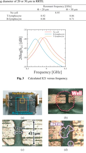
The frequency characteristics of the RRTE were simulated in HFSS software when the inserting cell was assumed as a single cell model[8]as the simple model where the dielec- tric constants of the inserting cell were assumed as those of the B- and T-lymphocytes[9]because the dielectric con- stant of the CTC was unknown at that time. Table 1 shows the complex permittivities of the B- and T-lymphocytes used this calculation.
The diameterΦof each cell was set to be 20 or 30μm to evaluate the variation of the resonant frequency by the difference of the cell size. Table 2 shows the calculated res- onant frequencies in case of inserting the cell having each size in the RRTE, where the whole length of the RRTE was designed to be 8.5 mm. Figure 3 shows the calculated trans-
Fig. 3 Calculated S21 versus frequency.
Fig. 4 Photograph of RRTE: (a) whole view, (b) outside of well inserting BiTio3in saline solution, (c) dimension of parallel electrode, (d) distribu- tion of BaTio3particles.
mission coefficients versus frequency when the diameter of the cell was set at 30μm. The calculated results indicate that the resonant frequencies are changed by the different cells.
2.3 Preliminary Experiment Using BaTiO3Particles Although the size of the RRTE should be designed to be micrometer-scale, the RRTE was fabricated in several hun- dred meter scale by using the photolithography as the early investigation by using the Duroid substrate whose relative permittivity and thickness of copper are 2.2 and 36 μm, respectively. Figure 4 shows the fabricated RRTE whose whole length was designed at 45 mm so as to resonate at around 5GHz because of easy observation of the frequency characteristics from a viewpoint of the dynamic range in our equipment. The measured frequency characteristics are shown in Fig. 5, where the parallel electrodes had three con-
Fig. 5 Measured S21 versus frequency.
ditions. There was no material in the parallel electrodes.
The saline solution was only dropped in those using the mi- cropipette, and the barium titanate (BaTiO3) particles were inserted in the saline solution. The reasons why the BaTiO3
particles were selected were that the size was similar to that of the cell and the handling was easy in the experiment.
It was confirmed that the resonant frequency was changed when the BaTiO3particles were inserted in the electrode.
3. Identification Sensitivity Enhancement Using Oscil- lator Circuit
3.1 Resonant Characteristics of Ring-Resonator Type of Electrode Using Cattle Organ Tissues
Since it is predicted that the loss tangent of the CTC may be poor[10], the resonant curves of the RRTE were observed by using the internal organs of the beef cattle such as liver, lung, and kidney to know how much identification sensitiv- ity will degrade. To investigate the individual difference of the organ and to confirm the reliability in this experiment, the same experiments were repeated at 5 times in each tis- sue.
Figures 7 and 8 show the measured frequency response for each tissue and the distributions of measured resonant frequencies versus organ tissue, respectively. In Fig. 8, the maximum displacement rate of the resonant frequency was about 2%. Focusing on the resonant curve, the high Q-factor is needed to well identify the organ tissue because obser- vation of the resonant frequencies among the frequency re- sponses were difficult because of high losses of the beef cat- tle organs.
3.2 Ring-Resonator Type of Electrode with Oscillator Cir- cuit
Because identifying the organ tissue was difficult, the os- cillator circuit consisting of the FET including a capaci- tance as the feedback circuit was introduced in the RRTE.
Figure 9 (a) shows the equivalent circuit of the RRTE con- nected with the oscillator circuit via transmission lines with a length ofl. Figure 9 (b) shows the fabricated RRTE. The
Fig. 6 Cattle organ tissue on RRTE.
Fig. 7 Measured S21 versus frequency.
Fig. 8 Distributions of measured resonant frequencies versus organ tis- sues.
oscillation frequency is decided by whole length of the ring- resonator and the complex permittivity of the organ tissues.
The dissipation loss of the organ tissue will be compen- sated by the oscillator circuit because the oscillator acts in the negative resistance condition[11]–[13], and thus, well- identification of the organ can be expected by observing the oscillation frequency spectrums. The oscillator circuit was constructed by the FET(NE76084) with the capacitance (C=3pF) in the source terminal. To investigate the individ- ual difference of the organ and to confirm the reliability in this experiment, the same experiments were also repeated 5 times for each tissue, where the gate to source voltage and
Fig. 9 RRTE connecting oscillator circuit.
Fig. 10 Measured oscillation frequency spectrums.
drain to source voltage were fixed to be −0.5V and 4.0V, respectively. Figures 10 and 11 show the measured oscilla- tion frequency spectrums in each beef cattle tissue and the distributions of the measured oscillation frequencies versus organ tissues.
It was confirmed that the oscillation frequency spec- trums were clearly separated in each tissue and the max- imum displacement rate of the oscillation frequency was about 1.1%. The distribution of the oscillation frequency for the organ tissue of the kidney was close to that of the liver. The reason is considered that the relative permittivity of the kidney is close to that of the liver in this frequency band[10].
Fig. 11 Distribution of measured oscillation frequency versus organ tis- sue.
From these results, the identification sensitivity en- hancement can be performed by using the RRTE connecting the oscillation circuit.
4. Conclusions
A ring-resonator type of electrode (RRTE) was proposed to detect the circulating tumor cell (CTC) for evaluation of the current cancer progression and malignancy in clinical appli- cations.
At first, the possibility of the CTC detection was nu- merically considered to calculate the resonant frequency of the RRTE catching the CTC, and it was evident that the RRTE with the cell has the resonant frequency inherent in the cell featured by its complex permittivity. To confirm the numerical consideration, the BaTiO3 particle, whose size was similar to that of the CTC, was inserted in the RRTE instead of the CTC as a preliminary experiment.
Next, the resonant frequencies of the RRTE with inter- nal organs of the beef cattle such as liver, lung, and kidney were measured for evaluation of the lossy materials such as the CTC, and degraded Q curves were observed because the Q-factors inherent in the internal organs were usually low due to the poor loss tangents.
To overcome such difficulty, the RRTE, the oscillator circuit consisting of the FET being added, was proposed to improve the identification sensitivity. Comparing the iden- tification sensitivity of the conventional RRTE, it has been improved because the oscillation frequency spectrum inher- ent in an internal organ could be easily observed thanks to the oscillation condition with negative resistance. Thus, the validity of the proposed technique has been confirmed.
The next step of this research will be to investigate the RRTE having genuine CTC in saline solution in the medical fields.
Acknowledgments
This work was supported by Grant-in-Aid for Scientific Research (A) (Grant No.16H01747) and (C) (Grant No.
JP18K04285) granted by JSPS in 2016 and 2018, respec- tively. The authors would like to express their gratitude to
Cell158, pp.1110–1122, Aug. 2014.
[2] F. Tanaka, K. Yoneda, N. Kondo, M. Hashimoto, T. Takuwa, S.
Matsumoto, Y. Okumura, S. Rahman, N. Tsubota, T. Tsujimura, K.
Kuribayashi, K. Fukuoka, T. Nakano, and S. Hasegawa, “Circulat- ing Tumor Cell as a Diagnostic Marker in Primary Lung Cancer,”
Clinical Cancer Research, vol.15, no.22, pp.6980–6989, Nov. 2009.
[3] K. Yoneda, F. Tanaka, N. Kondo, M. Hashimoto, T. Takuwa, S.
Matsumoto, Y. Okumura, N. Tsubota, A. Sato, T. Tsujimura, K.
Kuribayashi, K. Fukuoka, C. Tabata, T. Nakano, and S. Hasegawa,
“Circulating Tumor Cells (CTCs) in Malignant Pleural Mesothe- lioma (MPM),” Translational Research and Biomarkers, vol.21, no.S4, pp.472–480, Dec. 2014.
[4] P. Li, Z. Mao, Z. Peng, L. Zhou, Y. Chen, P.-H. Huang, C.I. Truica, J.J. Drabick, W.S. El-Deiry, M. Dao, S. Suresh, and T.J. Huang,
“Acoustic separation of circulating tumor cells,” Proc. f the National Academy of Sciences of USA, vol.112, no.16, pp.4970–4975, April 2015
[5] M. Eguchi, K. Horio, F. Kuroki, H. Imasato, and T. Yamakawa, “De- velopment of Pillar Electrode Array for Electrorotation Analysis of Single Cells,” Proc. World Automation Congress (WAC), June 2018.
[6] K. Horio, K. Matsuyama, M. Eguchi, and T. Yamakawa, “Con- sideration of Relationship between Shape and Angular Velocity of Particles under Electrorotation,” Proc. World Automation Congress (WAC), June 2018.
[7] G. Matthaei, et al, “Microwave Filters, Impedance-matching Net- works, and Coupling Structures,” pp.872–884, McGraw-Hill, 1985.
[8] V. Raicu and Y. Feldman, “Dielectric Relaxation in Biological Sys- tems,” Oxford University Press, 2015.
[9] J. Yang, Y. Huang, X. Wang, X.-B. Wang, F.F. Becker, and P.R.C.
Gascoyne, “Dielectric Properties of Human Leukocyte Subpopula- tions Determined by Electrorotation as a Cell Separation Criterion,”
Biophysical Journal, vol.76, no.6, pp.3307–3314, 1999.
[10] C. Gabriel, et al, “ Compilation of the dielectric properties of body tissues at RF and microwave frequencies,” Brooks Air Force Tech- nical Report, 1996.
[11] D.M. Pozar, “Microwave Engineering (second edition),” pp.641–
652, JOHN WILEY & SONS, INC., 1997.
[12] C.R. Poole and I.Z. Darwazeh, “A simplified approach to predict- ing negative resistance in a microwave transistor with series feed- back,” Proc. IEEE MTT-S International Microwave Symposium, June 2013.
[13] C. Poole, I. Darwazeh, H. Zirath, K. Eriksson, D. Kuylenstierna, and S. Lai, “Design and characterization of a negative resistance Com- mon Emitter InP Double Heterojunction Bipolar Transistor subcir- cuit for millimeter wave and submillimeter wave applications,” Proc.
European Microwave Conference, pp.933–936, Oct. 2014.
Futoshi Kuroki received the associate B.E.
degree in electrical engineering from Kure Na- tional College of Technology, Japan, in 1980, the B.E. degree in electronics engineering from Kyusyu Institute of Technology, Japan, in 1982, and the M.E. and Ph.D. degrees in electrical communication engineering from Tohoku Uni- versity, Sendai, Japan, in 1984 and 1987, respec- tively. From 1987 to 1995, he was a Research Associate at the Research Institute of Electri- cal Communication, Tohoku University. Since 1995, he has been with Kure National College of Technology, Hiroshima, Japan, where he is a Professor in the Department of Electrical Engineering and Information Science. He has been engaged in research work on electro- magnetic devices, circuits, antennas, and systems. Dr. Kuroki is a member of the Institute of Electronics, Information and Communication Engineer- ing (IEICE) in Japan, the Institute of Electrical and Electronics Engineers (IEEE) in USA.
Shouta Sora received the Associate B.E.
degree in 2018 and the B.E. degree in 2020 in department of electrical engineering and infor- mation science from National Institute of Tech- nology, Kure College Hiroshima, Japan, and now is currently working toward the M.E. de- gree in Tohoku University. He has been engaged in research work on medical applications. Mr.
Sora is a member of the Institute of Electron- ics, Information and Communication Engineer- ing (IEICE) in Japan.
Kousei Kumahara received the Asso- ciate B.E. degree in 2017 and the B.E. degree in 2019 in department of electrical engineer- ing and information science from National In- stitute of Technology, Kure College Hiroshima, Japan, and now is currently working toward the M.E. degree in Tohoku University. He has been engaged in research work on medical applica- tions. Mr. Kumahara is a member of the Institute of Electronics, Information and Communication Engineering (IEICE) in Japan.