Kyushu University Institutional Repository
鋼床版の溶接ルートき裂の疲労挙動と構造応答
杨, 沐野
https://doi.org/10.15017/1866286
出版情報:Kyushu University, 2017, 博士(工学), 課程博士 バージョン:
権利関係:
FATIGUE BEHAVIOR OF WELD ROOT CRACK AND STRUCTURAL RESPONSE IN ORTHOTROPIC
STEEL DECKS
Yang Muye
FATIGUE BEHAVIOR OF WELD ROOT CRACK AND STRUCTURAL RESPONSE IN ORTHOTROPIC STEEL DECKS
A Thesis Submitted
In Partial Fulfillment of the Requirements For the Degree of
Doctor of Engineering
By Muye Yang
to the
DEPARTMENT OF URBAN AND ENVIRONMENTAL ENGINEERING GRADUATE SCHOOL OF ENGINEERING
KYUSHU UNIVERSITY
Fukuoka, Japan
September, 2017
DEPARTMENT OF URBAN AND ENVIRONMENTAL ENGINEERING GRADUATE SCHOOL OF ENGINEERING
KYUSHU UNIVERSITY Fukuoka, Japan
CERTIFICATE
The undersigned hereby certify that they have read and recommended to the Graduate School of Engineering for the acceptance of this thesis entitled, ‘‘Fatigue Behavior of Weld Root Crack and Structural Response in Orthotropic Steel Decks’’ by Muye Yang in partial fulfillment of the requirements for the degree of Doctor of Engineering.
Dated: September, 2017
Thesis Supervisor:
___________________________
Prof. Shigenobu KAINUMA, Dr. Eng.
Examining Committee:
___________________________
Prof. Yoshimi SONODA, Dr. Eng.
___________________________
Prof. Hidenori HAMADA, Dr. Eng.
ABSTRACT
The orthotropic steel decks have been commonly applied to long-span bridges and expressways because of the structural properties such as low self-weight, high load-carrying capacity and high stiffness. The main components of an orthotropic steel deck including the deck plate, longitudinal stiffeners and transverse crossbeams, these members are connected by welding. In the past decades, severe fatigue cracks have been reported at several welded joints in orthotropic steel bridge decks in Europe and other countries. In Japan, many orthotropic steel bridges were extensively constructed in the 1960s-80s during the period of rapid economic growth. Until now, various types of fatigue damages to the steel decks were reported owing to long-term operation and the changed operating environment including the emergence of heavy-duty vehicles and increasing traffic volume beyond design expectations.
A fatigue crack initiation from the weld root tip is one kind of most common and adverse damage, which usually occurred from the rib-to-deck connection and rib-to-rib butt weld, etc. The rib-to-deck structure includes a large number of single-fillet weld joint, root crack is easy to occur due to the inadequate welding details in conjunction with the residual stress induced by the welding process and unfavorable weld shape. Besides, root crack cannot be observed by visual inspection, which might have severe impacts to bridge safety.
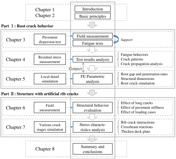
Depending on the randomness of vehicle loading in actual bridge, dispersion of fatigue life, and the indeterminacy of crack propagation. The objective of this research is to direct towards cracks at the welded joints of steel bridge with U-shape ribs. The principal aim is to investigate the fatigue behaviors and crack characteristics of welded joints. The methods used in this research is based on the dynamic experimental simulation and parametric numerical analysis. The dissertation is divided into two main parts: (I) Fatigue crack behavior analysis; (II) Structure response of artificial crack simulation.
In Chapter 1, the background and topic review was described, and structure of dissertation was presented.
In Chapter 2, the fatigue damage cases and related theoretical foundation was clarified.
The part I focused at certain location of orthotropic steel deck and conducted with crack behavior analysis which taking into account structural parameters and fabrication process. This part including three sub-objectives in Chapter 3, 4, 5.
In Chapter 3, the fatigue behaviors of rib-to-deck welded joints were experimentally evaluated according to the most adverse loading position. Typical crack patterns were obtained from fatigue tests by cutting and MPT inspection. The relationship between reference stress condition and crack depth of specimens could be understand, according to six types of structural parameters.
In Chapter 4, the cause identification of the crack initiation of this structural detail were clarified by
analyze on the fatigue test results. The effect of weld residual stress on root crack initiation were clarified by using a cutting method and thermo-elastic-plastic FE analysis. The fatigue cracking patterns and their influence factors were discussed by comparing the crack sizes and crack angles in the cross section.
In Chapter 5, the cracking mechanism and stress responses around root tip were analyzed by establishing the matching FE models, to verify with fatigue tests results. The effect of root gap shapes, weld penetrations, and plate thicknesses on crack initiation were discussed. Besides, various root crack depths were simulated in models to clarify the stress variations occurring during the propagation stage under cyclic loading.
The part II focused on the stress responses in different locations of orthotropic steel deck which including various crack combination, and investigated the structural characteristics and mechanical properties of structure. This part was investigated in chapter 6 and chapter 7.
In Chapter 6, to investigate the effect of rib fractures, and the combination of rib crack and rib-to- deck cracks, the field tests results were compared with FEA by simulating the long artificial cracks. The structure responses and stress behaviors were analyzed, the effects of asphalt stiffness and various loading positions were also discussed.
In Chapter 7, the FEA on three-span steel deck was conducted to investigate the stress characteristics of structure with artificial crack combinations. By establishing the solid-shell hybrid models, the interaction between rib cracks and other weld details were clarified. Thus not only the local stress around crack position, but also the crossbeam response was evaluated by hot spot stress method.
In Chapter 8, it summarized the conclusions of the obtained results for the experimental and
numerical studies.
ACKNOWLEDGEMENTS
After an intensive period of three years, today is the day: writing this note of thanks is the finishing touch on my dissertation. It has been an indelible period for me, I got so much help from many people and grown up under their care.
I would like to express my special appreciation and sincere gratitude to my supervisor Assoc. Prof.
Shigenobu KAINUMA. For his patience, motivation, enthusiasm, endless encouragement, immense knowledge and guide throughout my three years of research. He always been available to advise me even he is busy with his daily routine work, make him a great mentor. He inspired me about the research in any way deeply. Thank you for your kindness and for accepting me three years ago to experience your extensive knowledge in steel bridge. Likewise, my thousands of appreciation also goes to Advisory Committee, Prof. Yoshimi SONODA, Prof. Hidenori HAMADA. For their precious suggestions and insightful comments with regard to improve this research work. Thank you also for letting my defense be a memorable moment.
Additionally, thanks to our Prof. Shinichi HINO, the vice-president of Kyushu University. Thank you for giving me the chance to participate the site visit. I really learnt a lot form you even only have a talk for few times. You are our spiritual leader, I feel very grateful to be a member of your lab. I would also like to address my thanks to the tender secretary of my laboratory Ms. KATO, gentle teaching assistant Mr. HATAKEYAMA, and also goes to Mr. SHIBATA for his tremendous help, for his non-stop help throughout my experimental work. Moreover, I would like to thank Prof. Hanbin GE and Prof. Hohai JI for giving me the opportunity to perform my study in the Kyushu University, you are not only my best teachers but also helpful friends.
My special gratitude also is dedicated to the Ministry of Education, Culture, Sports, Science and Technology (MEXT) of Japan for providing financial study assistance during my doctoral program in Japan. My grateful acknowledgement. I'd like to show my grateful to Miss. OOIWA, she gave me help and care about all issues in my studying life.
Also, I wish to express my gratitude to my colleagues, seniors and juniors, who supported me during the research. They provided me not only with their academic knowledge but also with their enthusiasm.
I really enjoyed the study life here. A special thanks to Young-Soo JEONG San for supporting me during these years, he led me do a vast of experiment and taught me a lot. Without his help in patience, I will not achieve so good performance as now. I'd like to say thank you to my office neighbor Doctor Rui GUO. As a Chinese upperclassman, he gave me many useful advices. Last not least, there are my friends.
Thanks to Minami HIRAO, Hiroshi FUJIMOTO, Ryouta WATANABE, Jingxuan DU, Gaku
MASHIMOTO, Kousuke YAGI, Hiroyuki MOMOTA, Fumi YAMAGATA, Keita TANIGAWA, Shaofu
LIU, Katsuya YAMASHITA, we always get together, laughing and discussing something funny, it
makes me feel warm and confident to study abroad happily. Particularly to Miss. HIRAO and Miss.
YAMAGATA, you are great companions, we progress together and I will never forget your kind helps.
Finally, I would also like to take this opportunity to express the profound gratitude from my deep heart to my dear Mr. Right, and my beloved mother and sister. It is because of you, I didn’t feel lonely, got confidence and power to continue. All of you always there for me.
Thank you very much, everyone!
Muye Yang
Fukuoka, July, 2017.
TABLE OF CONTENTS
ABSTRACT ... I ACKNOWLEDGEMENTS ... III TABLE OF CONTENTS ... V LIST OF FIGURES ... IX LIST OF TABLES ... XIII
CHAPTER 1 INTRODUCTION ... 1
1.1 B
ACKGROUND... 1
1.2 O
BJECTIVES... 4
1.3 L
ITERATURE REVIEW... 6
1.3.1 Specifications of orthotropic steel deck structure ... 6
1.3.2 Structural parametric analysis ... 8
1.3.3 Fatigue experimental studies ... 9
1.3.4 Fatigue crack behavior and detections ... 11
1.3.5 Finite element method ... 12
1.4 O
UTLINE OF DISSERTATION... 13
CHAPTER 2 FATIGUE DAMAGES AND MECHANISMS ... 16
2.1 I
NTRODUCTION... 16
2.2 F
ATIGUE CASES IN ORTHOTROPIC STEEL BRIDGE DECKS... 17
2.3 F
ATIGUE MECHANISMS OF WELDED JOINT... 21
2.3.1 Fatigue life evaluation ... 21
2.3.2 Fatigue cracking process ... 23
2.3.3 Design philosophy and assessment ... 24
2.3.4 Other influence factors ... 26
2.4 M
ECHANICAL BEHAVIOR OF ORTHOTROPIC STEEL DECK... 27
2.4.1 Deformation of rib and deck plate connection ... 27
2.4.2 Mechanical behavior of the rib splice joint... 28
2.4.3 Mechanical behavior of other sub-systems ... 29
CHAPTER 3 EXPERIMENTAL ANALYSIS ON FATIGUE BEHAVIOR OF RIB-TO-DECK
WELD JOINT ...30
3.1 I
NTRODUCTION... 30
3.2 F
IELD LOADING TEST OF ORTHOTROPIC STEEL BRIDGE... 30
3.3 F
ATIGUE TEST... 32
3.3.1 Test specimen ... 32
3.3.2 Test set-up ... 34
3.3.3 Loading condition ... 37
3.4 T
EST PROCESS AND RESULTS... 40
3.4.1 Test process ... 40
3.4.2 Crack category ... 41
3.5 S
UMMARY... 46
CHAPTER 4 RESIDUAL STRESS TEST AND CRACK BEHAVIOR ANALYSIS ...48
4.1 I
NTRODUCTION... 48
4.2 E
XPERIMENTAL MEASUREMENT OF WELDING RESIDUAL STRESS... 48
4.2.1 Three-scale specimens and cutting method ... 48
4.2.2 Test and FE results comparison on residual stress ... 50
4.2.3 Welding residual stress of FE partial models ... 52
4.2.4 Effect of residual stress on full-scale specimen ... 55
4.3 P
ARAMETRIC ANALYSIS OF FATIGUE CRACK SIZES... 57
4.3.1 Crack sizes comparison ... 57
4.3.2 Effect of stress range on crack propagation ... 60
4.4 C
RACK PROPAGATION ANALYSIS... 63
4.4.1 Crack propagation directions ... 63
4.4.2 Effect of penetration rate on crack angles ... 64
4.4.3 Effect of weld toe on root crack ... 65
4.5 S
UMMARY... 66
CHAPTER 5 NUMERICAL ANALYSIS OF RIB-TO-DECK WELD JOINT WITH ARTIFICIAL ROOT CRACKS ...68
5.1 I
NTRODUCTION... 68
5.2 FE
MODELS... 68
5.2.1 FE models with non-crack ... 68
5.2.2 FE models with artificial root cracks... 71
5.3 P
ARAMETRIC ANALYSIS ON NON-
CRACK MODEL... 73
5.3.1 Effect of root gap shapes ... 73
5.3.2 Effect of weld penetration... 75
5.3.3 Effect of plate thickness ... 77
5.4 S
TRESS ANALYSIS OF MODELS WITH ARTIFICIAL ROOT CRACKS... 81
5.4.1 Effect of crack depth on stress response ... 81
5.4.2 Other influence factors ... 83
5.5 S
UMMARY... 85
CHAPTER 6 STRUCTURAL BEHAVIOR OF ORTHOTROPIC STEEL DECKS WITH ARTIFICIAL CRACKS IN LONGITUDINAL RIBS ... 87
6.1 I
NTRODUCTION... 87
6.2 F
IELD MEASUREMENTS... 88
6.3 C
OMPARISON OF FIELD RESULTS ANDFEA ... 90
6.3.1 FE models ... 90
6.3.2 FEA and field measurement comparison of double tire load tests ... 91
6.3.3 FEA and field measurement comparison of single tire load tests ... 93
6.4 C
OMPARISON OF RIB FRACTURE LOCATIONS... 95
6.4.1 Effect of the mid-span and quarter span cracks on stress responses ... 95
6.4.2 Torsional rigidity of rib with butt weld crack at quarter span ... 97
6.5 S
TRUCTURAL RESPONSES WHEN MULTIPLE RIBS FRACTURED... 98
6.5.1 FEA analysis under double tire loading ... 98
6.5.2 Structural responses under various transverse load cases ... 99
6.5.3 Effect of rib cracks on stress ranges at adjacent rib ... 101
6.5.4 Stress variations depending on pavement stiffness ... 103
6.6 S
UMMARY... 105
CHAPTER 7 STRESS CHARACTERISTICS OF DECK PLATE AND CROSSBEAM WITH BUTT WELD CRACK COMBINATIONS ... 106
7.1 I
NTRODUCTION... 106
7.2 FE
ANALYSIS OF RIB CRACK COMBINATIONS... 107
7.2.1 FE models ... 107
7.2.2 Local deformations at crack cross section ... 110
7.2.3 Local stress variations at crack cross section ... 112
7.2.4 Stress response of other structural details ... 113
7.3 S
TRESS CHARACTERISTIC OF RIB-
TO-
CROSSBEAM CONNECTIONS... 115
7.3.1 Effect of transverse loading on cut-out stress ... 115
7.3.2 Effect of longitudinal loading on cut-out stress ... 116
7.3.3 Evaluation on cope hole stresses by hot spot method ... 118
7.4 S
TRESS CHARACTERISTICS OF STRUCTURE WITH16
MM-
DECK PLATE... 121
7.4.1 Effect of rib cracks on stress ranges at adjacent rib ... 121
7.4.2 Effect of pavement stiffness on structural response ... 122
7.4.3 Effect of rib cracks on cut-out stresses ... 122
7.5 C
ONCLUSIONS... 124
CHAPTER 8 SUMMARY AND CONCLUSIONS ... 126
8.1 S
UMMARY OF WORKS... 126
8.2 C
ONCLUSIONS... 127
8.3 R
ECOMMENDATIONS FOR FUTURE WORKS... 129
BIBLIOGRAPHY ... 131
LIST OF FIGURES
Figure 1.1 Perspective drawing of a typical orthotropic steel deck structure... 1
Figure 1.2 Typical fatigue cracks in orthotropic steel bridges ... 3
Figure 1.3 Occurrence proportion of typical fatigue cracks in Japan ... 3
Figure 1.4 Root-deck cracks at rib-to-deck welded joints ... 5
Figure 1.5 Rib-to-rib cracks at field weld [10] ... 5
Figure 1.6 Typical shape of U-rib in orthotropic steel decks ... 7
Figure 1.7 The cut-outs of crossbeam at rib-to-crossbeam connections ... 9
Figure 1.8 Cracks of butt weld and fillet welded joint ... 11
Figure 1.9 Scheme of this study ... 15
Figure 2.1 Fatigue cracks of steel bridge in Japan [18] ... 18
Figure 2.2 Crack visible at downside and upside of deck plate ... 19
Figure 2.3 Root crack visible under wearing course [24] ... 19
Figure 2.4 Root cracks in other countries [79] ... 21
Figure 2.5 Crack occurred at the rib splice joint ... 21
Figure 2.6 Fatigue strength and S-N curve of JSSC specification ... 22
Figure 2.7 A schematic of the typical fatigue growth behavior of cracks ... 23
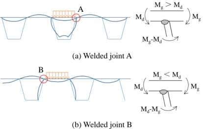
Figure 2.8 Effective stress at the weld joint [10] ... 27
Figure 2.9 Local effects on rib-to-deck connection from wheel loading ... 28
Figure 2.10 Mechanical behavior of the rib splice joint ... 29
Figure 3.1 Field measurements in loading test of orthotropic deck bridge ... 31
Figure 3.2 Field stress histogram measurement for three-days ... 32
Figure 3.3 Three views of specimens ... 32
Figure 3.4 Weld joint photos of specimens in etching test ... 33
Figure 3.5 Test setup and loading cases ... 35
Figure 3.6 Loading jig and wheel load dispersion ... 35
Figure 3.7 Loading dispersion static tests ... 37
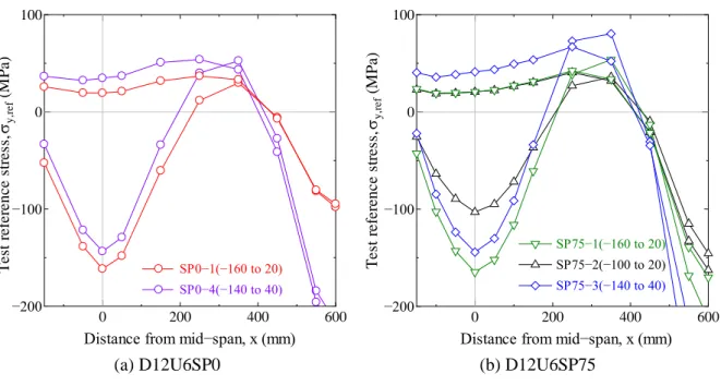
Figure 3.8 Reference strain distributions of static loading tests ... 37
Figure 3.9 Measured reference stress range of specimens ... 40
Figure 3.10 Reference stress ranges and cycles during fatigue loading tests ... 40
Figure 3.11 Typical crack patterns of test results ... 41
Figure 3.12 Crack depth distribution of deck/root cracks ... 43
Figure 3.13 MT inspections of typical cracking specimens [100] ... 46
Figure 4.1 Dimensions and cutting positions of specimen ... 49
Figure 4.2 Dimension of specimens and welding joints ... 49
Figure 4.3 Location of strain gages in the cutting method (unit: mm) ... 50
Figure 4.4 Residual stress distribution comparison ... 50
Figure 4.5 FE analysis model and root gaps ... 51
Figure 4.6 Temperature dependencies of the thermal and mechanical properties ... 51
Figure 4.7 Residual stress distribution in deck plate to U-rib ... 52
Figure 4.8 FE analysis results ... 54
Figure 4.9 FE analysis on principal stress of D12U6SP75G0 ... 54
Figure 4.10 The location of cut out pieces of specimen ... 55
Figure 4.11 Residual stress distribution comparison ... 56
Figure 4.12 Measured reference stress of D12U6SP75 ... 57
Figure 4.13 Definition of root crack parameters ... 58
Figure 4.14 Measures data of root cracks of all specimens ... 58
Figure 4.15 Effect of structural parameters on root crack propagation ... 59
Figure 4.16 Effect of weld penetration rate on crack propagation ... 60
Figure 4.17 Relationship between crack depth and length (Effect of penetration rate)... 61
Figure 4.18 Effect of weld penetration rate on crack propagation ... 62
Figure 4.19 Relationship between crack depth and length (Effect of plate thickness) ... 62
Figure 4.20 Dynamic reference stress range at mid-span ... 62
Figure 4.21 Root crack propagation angles of cross-sections ... 63
Figure 4.22 Crack depth comparison of D12U6SP0-1 cross sections ... 64
Figure 4.23 Average crack tip angles of specimens under -140 to 40 MPa ... 64
Figure 4.24 Comparison of root and toe crack tips of D12U8SP50-1 ... 65
Figure 4.25 Comparison of toe and root cracks (40 to -140MPa) ... 66
Figure 5.1 FE models and the loading conditions ... 69
Figure 5.2 Basic FE model and the dimensions of root gaps (D12U6SP75)... 69
Figure 5.3 Stress distributions of specimens in longitudinal direction ... 71
Figure 5.4 Relationship between reference stress and root stress ... 71
Figure 5.5 Stress distribution at welded joint of model D12U8SP50 ... 71
Figure 5.6 Definitions of FE Analytical model ... 72
Figure 5.7 Transverse stress of models in cracking direction with artificial root cracks... 73
Figure 5.8 Details of tria-gap of model D12U6SP75 ... 73
Figure 5.9 Comparison of models with different root gap geometry (D12U6SP75) ... 74
Figure 5.10 Major principal stress contours ... 75
Figure 5.11 Effect of weld penetration rate on root tip stress of D12U6 ... 76
Figure 5.12 Stress comparison of (D12) U8SP75/U8SP50/U6SP75 ... 76
Figure 5.13 Stress distribution in y direction at mid-span ... 77
Figure 5.14 Stress response of models in longitudinal direction... 77
Figure 5.15 Effect of deck plate thickness on stress ... 78
Figure 5.16 Unit stress comparison of D12/D14/D16 deck plate under P
max... 78
Figure 5.17 Displacements of root tips in y and z directions ... 78
Figure 5.18 Structural deformation and principal stress of root tip at mid-span ... 79
Figure 5.19 Structural deformation and principal stress of root tip at mid-span ... 80
Figure 5.20 Stress variations in deck plate thickness ... 81
Figure 5.21 Stress variations at crack tip surrounding under half loading cycle ... 82
Figure 5.22 8mm-crack models during half cycle ... 82
Figure 5.23 Major principal stress contours of 8 mm-crack model ... 83
Figure 5.24 Stress range comparison of reference point and crack tip surrounding ... 84
Figure 5.25 Effect of penetration rate on stress during crack propagation. ... 85
Figure 5.26 Effect of structural dimensions on fatigue strength. ... 85
Figure 6.1 Field welding of trough splice joints [10] ... 87
Figure 6.2 Loading cases of field measurement (Unit: mm) ... 89
Figure 6.3 Artificial cracks by gas-cut in actual bridge ... 89
Figure 6.4 FE model of solid elements ... 90
Figure 6.5 FE models with artificial cracks ... 91
Figure 6.6 Test results and FEA comparisons ... 92
Figure 6.7 Displacement of deck plate bottom... 93
Figure 6.8 Transverse stress of deck plate bottom ... 94
Figure 6.9 Longitudinal stress of rib bottom ... 94
Figure 6.10 Images of artificial cracks in FE models (Unit: mm)... 95
Figure 6.11 Comparison of the mid-span and quarter span cracks ... 96
Figure 6.12 Deformation of D3-Qua model ... 96
Figure 6.13 Crossbeam deformation of the models with quarter crack under loadcase2 ... 98
Figure 6.14 Stress responses with rib-to-rib cracks at quarter span ... 98
Figure 6.15 Details of various models with artificial crack combinations at mid-span ... 99
Figure 6.16 Deformations at mid-span of models ... 100
Figure 6.17 Stress distribution at mid-span under three loading positions of model N ... 101
Figure 6.18 Longitudinal stress of rib bottom under the load position t3 ... 102
Figure 6.19 Effect of pavement stiffness on structural response at certain location ... 103
Figure 6.20 Stress and stress ratio variations depending on the pavement stiffness ... 104
Figure 7.1 The cut-outs and typical cracks at crossbeams ... 106
Figure 7.2 Solid-shell hybrid element models... 108
Figure 7.3 Loading conditions of FE models ... 109
Figure 7.4 Major principal stress contours of models under t1 (Deformation: 100) ... 110
Figure 7.5 Deformation of the deck plate ... 111
Figure 7.6 Transverse stress distribution at the bottom of the deck plate ... 112
Figure 7.7 Longitudinal stress distribution at the bottom of ribs ... 113
Figure 7.8 Stress distributions at rib-to-deck connections in longitudinal direction ... 114
Figure 7.9 Toe stresses at rib-to-deck connections in longitudinal direction... 114
Figure 7.10 The crossbeam stress of rib2 under transverse loading t1 ... 115
Figure 7.11 Stress distributions at middle axial plane of cut-outs in model-e ... 116
Figure 7.12 Crossbeam details of FE models ... 117
Figure 7.13 Target crossbeam and five longitudinal loading positions ... 117
Figure 7.14 Maximum principal stresses of model-f crossbeam ... 118
Figure 7.15 Maximum principal stresses at Toe7 of cope holes ... 118
Figure 7.16 Comparison of inside and outside stresses at rib2 by hot spot method ... 119
Figure 7.17 Node stress and hot spot stress hs1/2(outside) of crossbeam ... 120
Figure 7.18 Comparison of node stress / hot spot stress at cope hole path ... 120
Figure 7.19 Longitudinal stress distribution of rib1 ... 121
Figure 7.20 The structural response of deck plate bottom at mid-span of 16mm-models ... 122
Figure 7.21 The stress distributions at scallops in middle-axial plane of crossbeam ... 123
Figure 7.22 The stresses at welded joint of cope holes ... 123
LIST OF TABLES
Table 1.1 Dimensions of U-rib in orthotropic steel decks ... 7
Table 2.1 Typical cases of bridge damages in Japan [73] ... 18
Table 2.2 The cases of through-deck crack of steel bridges in Holland [77] ... 20
Table 2.3 Review of range of detail categories in different codes ... 22
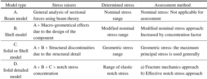
Table 2.4 Type of stress for fatigue assessment ... 26
Table 2.5 Assembly and description of orthotropic deck systems and their behavior [4] ... 29
Table 3.1 Dimensions of the orthotropic steel decks of A1 Bridge ... 31
Table 3.2 Chemical composition and mechanical properties ... 33
Table 3.3 Welding conditions of specimens ... 33
Table 3.4 Dimensions of specimens ... 34
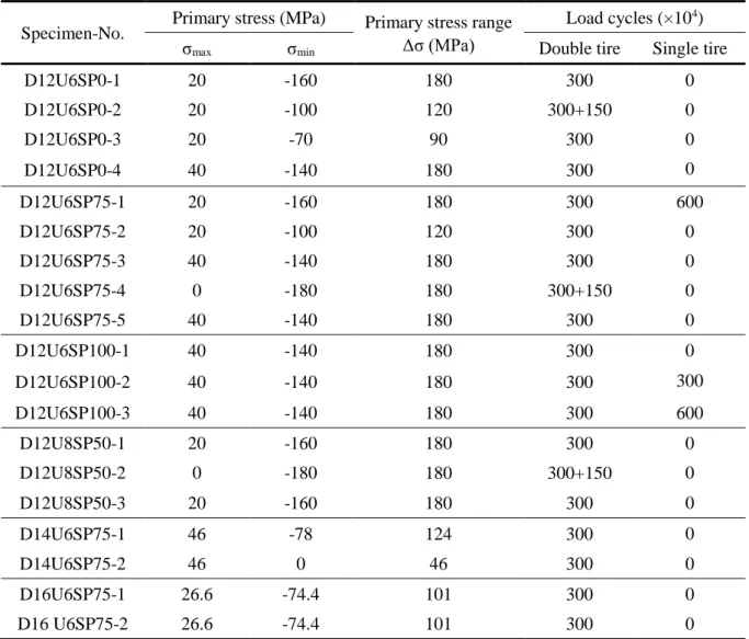
Table 3.5 Stress conditions of all specimens ... 39
Table 3.6 Relationship between stress condition and crack depth ... 43
Table 3.7 Test stresses and the measured crack depth ... 44
Table 4.1 Welding conditions of three-scale specimens ... 49
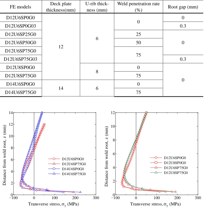
Table 4.2 Parameters of FE analysis models ... 53
Table 4.3 Geometry of weld toe ... 65
Table 5.1 Loading cases of FE models ... 70
Table 5.2 The correlation coefficient between root tip and reference stress ... 70
Table 6.1 Effect of the rib-to-rib crack locations on structural responses ... 96
Table 6.2 Maximum stress range at the bottom of rib1 and equivalent conversion ... 102
Table 7.1 The models with artificial cracks at ribs ... 109
Table 7.2 Criteria for deflection of orthotropic plate decks ... 111
Table 7.3 The relative displacement and allowable deflection of deck plate ... 111
Table 7.4 The maximum stress range and the amplification of rib1 ... 121
Chapter 1 Introduction
1.1 Background
The orthotropic steel decks (OSDs) have been commonly applied to long-span bridges and expressways because of the structural properties such as low self-weight, high load-carrying capacity and high stiffness [1]. There are some other good characteristics like slenderness, durability, shop welding and rapid construction [2] also given the orthotropic steel decks high popularity all over the world. An orthotropic steel deck (OSD) consists of a deck plate supported in two perpendicular directions by a system of longitudinal stiffeners and transverse crossbeams, which are spanned by main girders in turn [3]. Orthotropic bridges have been built in several ways, and there are many different details and typical connections. Most elements are connected by welding. A part view of a typical orthotropic steel deck structure as shown in Figure 1.1.
Figure 1.1 Perspective drawing of a typical orthotropic steel deck structure
The development of the OSD began in the 1930’s in Germany, and continued throughout the last century [4]. In the post-war the orthotropic systems were favored and further improved [5]. Many orthotropic steel decks were constructed in Europe and other countries since the 1960’s. Nowadays there are more than 1000 orthotropic steel bridges in Europe, out of which 86 are in the Netherlands. In Asia, there are several bridges that are built or being built, especially in Japan and China [6]. In the USA, their number of is remarkably small as only 51 out of its 650,000 bridges are orthotropic steel bridges [7].
9
2 8 4
1
3
6
7 5
1 Deck plate 2 Crossbeam 3 Main girder
4 Slice of longitudinal rib 5 Cut-out of crossbeam
6 Welded connection of longitudinal rib to deck plate
7 Welded connection of longitudinal rib to web of crossbeam
8 Welded connection of web of crossbeam to deck plate
9 Welded connection of crossbeam to
main girder
The orthotropic steel deck structures are widely used in longest-span bridges, for example, the Akashi- Kaikyo Bridge situated in Japan is a representative bridge.
Despite inherently possessing excellent structural properties of the OSD system, the fatigue damages have been observed earlier than expected in several bridges built with orthotropic decks [4]. Orthotropic steel decks have a relatively long service life, but the OSDs have shown prone to fatigue and are expensive to repair if critical cracks appear and this must be taken into consideration during design and construction [1]. Therefore, take full account of the economy and durability, the OSD would become an economical alternative when the following issues are important: lower mass, thinner sections, rapid installation, and cold-weather construction [8].
The lower superstructure mass is the primary reason for the use of orthotropic decks in long-span bridges. Generally, the OSD allow a decrease in the deadweight to about 1/3 to 1/2 compared with that of concrete bridges [9]. The amount of material to be saved increases with the length of the spans (AISC, 1962). For most of the long-span cable supported bridges, it is a significant improvement when the dead load reduction achieved by abandoning the reinforced concrete deck and switching to an OSD system.
Because the structure dead load causes 60 to 70% of the stresses in the cables and towers of long span bridges [10,11]. Besides, the improved performance of the bridge during an earthquake also related with its lower self-weight (Magnus and Sun, 2000).
According to statistics in Japan, the steel bridges accounted for about 40% of the total number of bridges on the major expressways in 2003 [12]. The vast majority of orthotropic steel bridges were extensively constructed in the 1960s to 1980s. The fatigue cracks have been reported in the welded joints of OSDs after several years in service [13–15]. This is partly a consequence of the significant increase of both traffic load and the fact that orthotropic decks chiefly were designed with regard to static load behavior [16].
In the last decades, due to the changed operating environment including the emergence of heavy-duty vehicles and increasing traffic volume, several fatigue cracks were detected in the deck structures of these bridges under the heavy vehicle lanes. Especially for the bridges in some important transportation routes which over 20years of service with the frequent passage of overloaded transport vehicles [17]. In addition, an OSD is involved the numerous plates and welded joints, as a consequence of high cyclic stresses by wheel loads, in conjunction with inevitable fabrication defects have seen an increase in fatigue cracks. Fatigue cracks have been recognized as a major concern in OSDs.
The ribs in the OSD can either be open or closed. The most common type is closed trapezoidal ribs
[10]. Advantages of an open rib system are ease of production, inspections and maintenance as well as
flexibility in dimensions and easy assembling with rest of the deck [4]. However, about twice as much
welding is required in a deck with open stiffeners compared to an equivalent deck with closed ribs. An
orthotropic deck with closed stiffeners has a significantly better capacity to distribute the traffic loads
compared to a system with open ribs (AISC, 1962). The high flexural and torsional rigidity of the closed
rib system makes it superior regarding erection and construction of the bridge. However, the field splices
for closed ribs are more difficult to perform than the ones for open ribs. Also the fatigue sensitive welds between the deck plate and stiffener requires high quality and care in fabrication [4].
After 1975, the U-shape longitudinal rib was mainly used in OSD construction in Japan. For the bridge structure with U-ribs, the following typical fatigue cracks have been reported in recent years [15], as shown in Figure 1.2. These fatigue cracks mostly occurred at the welding connections between the ribs and crossbeams; the rib-to-deck welded joints; and the butt welds of trough ribs, etc. The proportion of typical crack types at the Metropolitan Expressway, Hanshin Expressway[18] and the statistical analysis on urban highway by Mori et al [14], as shown in Figure 1.3.
Figure 1.2 Typical fatigue cracks in orthotropic steel bridges
Figure 1.3 Occurrence proportion of typical fatigue cracks in Japan
Among the various fatigue cracks reported in OSDs in Japan, the weld toe crack which located at the rib-to-cross beam connection(type ○ 4 ) with a partially welded joint, and the crack occurring at the
Butt joint of trough rib ② Vertical stiffener
to deck plate ③
Crossbeam to main girder web connection; others ⑤
Intersection of trough rib and crossbeam ④
Trough rib to deck plate connection ①
19%
5%
26%
47%
5% 14%
6%
31%
36%
5% 19%
6%
32%
39%
4%
Trough rib-to-deck plate connection Butt joint of trough rib
Vertical stiffener to deck plate
Interaction of trough rib and crossbeam Others
Metropolitan Expressway Hanshin Expressway
Mori et al.
(7000+)
(1102) amount: (161)
①
②
③
④
⑤
①
②
③
④
⑤
connection of vertical stiffener to deck plate(type ○ 3 ), are most common types. Because for either open or closed ribs in the OSD, crack types ○ 3 and ○ 4 might occurred. However, a crack occurred at root tip of rib-to-deck connection (type ○ 1 ) or at butt joint of trough ribs (type ○ 2 ) are the two types of principal crack modes associated with the OSD with U-shape ribs. It has been reported that fatigue cracks occurred at the field welds of U-ribs account for about 5~6% of the total damage types in orthotropic steel decks [14]; the fatigue cracks initiated at the weld roots of the fillet welds accounts for about 14~19% of the total damage types in OSDs [19].
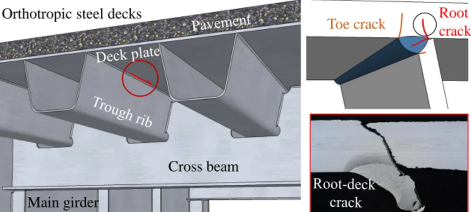
Fatigue cracks in orthotropic steel bridges significantly occurred at partial-penetration fillet-welded connections owing to the cyclic load stress. Rib-to-deck welded connections are directly supported the traffic, and submitted to local transverse bending moments. Besides, high residual stress and inherent defects existed at welded joint. Moreover, the variable combination of local load effects made it susceptible to fatigue cracking. A rib-to-deck crack (type ○ 1 ) usually initiated at the weld root, and propagated into the deck plate or through the weld bead. These fatigue cracks initiated from the hidden location might causing other secondary damages. For instance, the root-deck cracks have potential directly lead to pavement damages such as asphalt cave in, and then affect traffic safety. In particular, the root-deck crack is very hard to be detected and repaired even after it grown through the deck plate due to the covered wearing surface, which might have serious implications to bridge safety. Thus, the fatigue cracks of the weld root between the deck plate and U-rib are one of the most serious cracks, and have received much attention [20]. Recently, even the long through thickness root cracks have been reported and are gradually increasing in occurrence [13,14,21,22].
The rib-to-rib cracks (type ○ 2 ) might be propagate to be a large crack rapidly once this type of crack occurred, because the bottom of U-ribs mainly subjected to the tensile stress in service. Moreover, the longitudinal ribs were usually connected by field welding, most of the rib cracks were found in the welding material, along the lines of the butt welds [23]. Thus the quality of butt welded joint which depend on the site fabrication might be not so stable relative to the shop welding. The occurrence of fatigue cracks at multiple U-rib were often been detected in actual bridges.
At present, U-ribs account for about 60% stiffeners in the OSD construction of national road in Japan.
Therefore, a large number of single-fillet weld joints and butt joints are existing in steel bridges, because of the wide use of closed ribs [24]. Above all, study on the fatigue behavior of these welded joints and root cracks in OSDs with U-ribs would always be an important issue that we face.
1.2 Objectives
The research presented in this thesis is directed towards cracks at the welded joints of steel bridges
with closed stiffeners. The principal aim is to investigate the fatigue behaviors and cracking
characteristics of welded joints in OSD. For an OSD structure, the crack types which associated with U-
rib component could be mainly divided into three categories as mentioned previously:
Category-1. Cracks in the longitudinal weld between deck plate and rib.
Category-2. Cracks in the butt joint of rib splice.
Category-3. Cracks in the connection between longitudinal rib and crossbeam.
This thesis mainly deal with the case that cracks occurred at root tip of U-rib, and the rib cracks located at mid-span between two crossbeams, which are defined in category 1 and 2 above. Besides, the stress characteristics of the welded joint between rib and crossbeam would be effected by category 1 and 2, and then Category 3 crack might be easier to occur.
Firstly, the category-1 is the crack in the longitudinal weld between deck plate and rib. There are four crack initiation positions in the rib-to-deck connection, as shown in Figure 1.4. Among them, only root cracks were observed in actual bridge in Japan, and the root-deck crack was detected more frequently than the root-bead crack based on the field investigation. The root-deck is recognized as one of the most dangerous cracks in OSD. Moreover, there are numerous factors influencing the structural performance and its cracking mechanism still insufficient. Therefore, the local stress of rib-to-deck fillet weld and the crack patterns of root-deck welded joints were investigated in this study by test and numerical parametric analysis.
Figure 1.4 Root-deck cracks at rib-to-deck welded joints
Figure 1.5 Rib-to-rib cracks at field weld [10]
Secondly, the crack in the butt joint of rib splices (Category-2) as shown in Figure 1.5, would lead to the changing of global stress response. The local stress would also be enlarged which is important for the security prediction and bridge maintenance. It is significant to consider the combination of rib
Orthotropic steel decks
Cross beam Main girder
Root crack Toe crack
Field welding of U-ribs Crack at butt weld
Interaction of two cracks
fractures and rib-to-deck cracks, the mutual effect of large cracks at adjacent U-ribs. In this study, the global structural response of different cracked combinations were clarified by consider the different loading cases and pavement stiffness according to seasonal temperatures. Furthermore, the stress characteristics at the connection between rib and crossbeam (Category-3) were evaluated under various loading positions.
1.3 Literature review
There were many provisions regarding the structural dimensions of OSD bridges, and the criteria for deflection, displacement and penetration rates were suggested in different specifications. Besides, the cracking mechanisms of fatigue cracks in OSD were studied by several researchers. In particular, the local stress around rib-to-deck welded joints had been investigated based on experimental and numerical analysis results. In recent years, various field measurements, fatigue tests, and stress analyses have been conducted [9-11]. Fatigue tests of full-scale orthotropic steel decks have also been carried out, focusing on determining fatigue resistance and demonstrating the applicability of the fatigue assessment approaches for various structural details [12]. Most of these studies investigated the fatigue behaviors of rib-to-deck welded joints [13], rib-to-crossbeam welded joints [14], and the variation of these flexural stresses at the deck plate and U-ribs under the action of wheel loads [15]. An overview of previous research is presented in the following:
1.3.1 Specifications of orthotropic steel deck structure
The stiffeners of OSD were developed with various cross sections, including open stiffeners and closed stiffeners. To increasing the stiffener span length and reduce the number of crossbeams needed and thus reduce the number of structural elements and connections, it was found that the closed stiffener with one-side fillet weld is a good solution. Large cost savings resulted from the reduced amount of welded connections. For instance, a weld length of the rib-to-deck welded joint could reduce to 50%
achieved by the one-sided longitudinal welds compared with the both sided welds of the open stiffeners.
Usually, the V, U and Trapezoidal shapes were used as closed rib. They were made from cold pressed plates and were known as “Trough” stiffeners. Initially the V-shape was used in OSDs, with a depth of 200 mm and a plate thickness of 6 mm, but due to its small cross sectional area, the increase in bending capacity was limited compared to that of the open stiffeners. Then, an improvement was the U-shaped stiffener. Tromp reported tests on U-shaped stiffeners for crossbeams in Floating Decks and Ypeij [25]
showed the application of these decks. The bottom of these stiffeners acts like a true bottom flange and the maximum spans are approximately 3.5 m.
In Japan, the U-shape longitudinal rib were widely used in steel bridge constructions with the increase
in numbers of medium-sized span. At present, the application of U-shape rib has become mainstream
for the rationality of structure. Except some special case, the U-ribs are hardly used in curved bridges,
because it is difficult to fabricate curved U-ribs. In general, the dimensions of U-rib were based on the
recommendation by Japan Society of Steel Construction (JSSⅡ08-2006)[26], as shown in Figure 1.6.
Figure 1.6 Typical shape of U-rib in orthotropic steel decks
Moreover, the requirements for fatigue design should be significant. The revision of “Specifications for Highway Bridges” in 2002 enhanced the provisions of the fabrication and construction of OSD according to fatigue design [27]. Based on “Fatigue design guidelines for steel highway bridges” [21], the applicability of an OSD should follow as:
1) The spacing between crossbeams, L≤2.5m
The structural details were designed different before and after 2002 in Japan, because of the revision of specification. Therefore, the crossbeam spacing is limited to 2.5m in the conventional structure currently, but the case of 3~4m spacing were also existed.
2) The dimensions of typical U-rib
At first, three types of U-rib was adopted: 300×220×6-30, 320×240×6-30, 320×260×6-30, the radius of cut-outs are set to R=5·t=30mm. After 1983, the type of 300×220×6-30 was canceled, and 8mm-thich rib was added. The radius of cut-outs were all changed into R=40mm. The parameters of these four types of U-rib as shown in Table 1.1 .
Table 1.1 Dimensions of U-rib in orthotropic steel decks
Specimens A A’ B H t R e
xI
x×10
4(mm) (mm) (mm
4)
① 320×240×6-40 320 319.4 213.3 240 6 40 88.6 2460
② 320×260×6-40 320 319.4 204.4 260 6 40 99.1 3011
③ 320×240×8-40 324.1 323.3 216.5 242 8 40 89.9 3315
④ 320×260×8-40 324.1 323.3 207.7 262 8 45 100.3 4055 3) Thickness of deck plate t
d, 12mm ≤ td ≤16mm
In addition, to ensure the fatigue durability of OSD, the provisions of the steel deck provided in fatigue guidelines. The revision of “Specifications for Highway Bridges” in 2012 shows the deck plate thickness should increase from 12mm to 16mm to prevent the fatigue cracks propagating through the deck plate.
a details
H
A A’
![Table 2.2 The cases of through-deck crack of steel bridges in Holland [77]](https://thumb-ap.123doks.com/thumbv2/123deta/9919028.1919936/38.892.80.767.316.621/table-cases-deck-crack-steel-bridges-holland.webp)
![Table 2.5 Assembly and description of orthotropic deck systems and their behavior [4]](https://thumb-ap.123doks.com/thumbv2/123deta/9919028.1919936/47.892.130.807.653.1108/table-assembly-description-orthotropic-deck-systems-behavior.webp)