NII-Electronic Library Service
!iigc,,g,.],,,.,,,.,,,,,,,.,,.,
1Ir,n,a,l.,O,fi.S.tg".Cft"A'r})""Nd.F307"6ftrJU.e.ttEnlesn7gineering
spt3re,,ew#etipeefik6igNfftu6t.Ex
LATERAL
SHEAR
CAPACITY
OF
ONE-BAY
ONE--STORY
REINFORCED
CONCRETE
FRAMED
SHEAR
WALLS
WHOSE
EDGE
COLUMNS
OR
EDGE
BEAMS
FAIL
IN
SHEAR
'
by
Masahide
TOMII'
and
Fumiya
ESAKI'",
Members
of
A.I.J.
from
the
horizontal
direction
inthe
wallprop-agate
to
the
ends
of eqge columnsand
edgebeams
with
the
same
anglee,
When
either
the
ends ofedge columns
or
those
of
edge
beams
fail
in
shear
the
wallfails
in
shear atthe
sametime
'because
it
cannotbear
th6
increment
ofthe
lateral
force
due
to
the
re-distribution.Consequently,
the
lateral
shear
capacity
of
shear
wallsis
the
lateral
force
carried
by
the
shear wall wheneither
the
ends of edge columns orthose
of edgebeams
1,
lntroduction
The
shearfailure
modes of asymmetric one-bay one-stoTyframed
shear wall{hereafter
referredto
as "shear wall")can
be
classified
into
two
typical
types
ksee
Fig.
D.
If
the
boundary
frame
canbear
the
reactiondue
to
the
dilation
of
the
shear crackedinfilled
wallpanel
(hereafter
referredto
as "wall")forming
diagonal
compressien
field,
the
type
is
the
slipfailure
ofthe
wall shownin
Fig.
1
a.On
the
otherhand,
if
the
boundary
frame
cannotbear
the
reaction,the
type
is
the
shearfailure
of edge columns or edgebeams
(see
Fig.1b).
If
the
edge columnsfail
in
shear,bearing
'
capacity of
the
shear walldecreases
andthe
upper stories supportedby
the
fihear
wall arein
danger
offalling.
To
prevent
a suchdangerous
brittle
failure,
it
is
necessaryto
estimatethe
lateral
shear capacities of shear wallscorresponding'
t6
the
shearfailure
modes.Although
some estimating methods ofthe
lateral
shear capacity ofshear
viTalls
failing
in
shearhave
been
pro-posedi}-4},
they
are notbased
onthe
shearfailure
modes exceptthe
Mochizuki's
proposition`).
Dr.
Mochizuki
has
shown
the
expressionsfor
each shearfailure
mode.However,
his
analysis makesit
difficult
to
present
the
rationalexpressions,
because
the
member stresses necessaryto
calculatethe
lateral
shear capacity aredetermined
by
usingthe
assumptiondifferent
from
the
analytical results ofthe
cracked
shear
wallsS).The
objective
ofthis
paper
is
to
present
the
expresgionfor
estimating adequatelythe
lateral
shear capaeity of shearwalls
dominated
by
the
shearfailure
oftheir
edge columns or edgebeams.
The
expressionis
derived
by
consideringthe
mechanism of shear tesistance couespondipgto
the
failure
mode of a shear wall.In
this
derivation,
the
rationalassumptions
based
onthe
orthotropic elasticplate
analysis ofthe
cracked shear walls are used andthe
multipleregression analysis of
the
experimental resultsis
made.'
2.
Assumptions
for
Analysis
To
derive
the
expression,
the
following
assumptions are llsed(see
Fig.1
b).
1)
The
shear
cracks
inclining
atthe
anglee
'
g}+trtiipZfraiiurq
t8
tlshearga
±iureg'etr;,h
LE・
+iz
.g2g33ubb
]be
g
2g
2-e.2 sPeareraok.'s'
L.'a
・.,
.'
'
.pl,,'.,i・:・
'
.l.SII..4.・Ig-'
Q,l
I
(a)
The ofd.
La,
t,-a, pattern of a sltp a walZFig.1
Typical
patterns
ef
+g.
2tttt
fa±lurekzleenter
'sectton,b-.tg.h
2 .-gh2V-eni2-4T
(b)
"a pattern of a shear failnreof a boundary frame
shear
failuie
of shear wallsi
Professor
ofStructural
Engineering,
DepaTtment
ofATchitecture,
Faculty
ofEngineering,
Kyusyu
Univ.,
Dr.
Eng,
#
Research
Assistant
ofStructural
Engineering,
Department
ofArchitecture,
Faculty
ofEngineering,
Kyusyu
Univ.
,
Mr,
Eng.
(M,an"s:[ipt
TeccivedOctober
13,
1986)
-81-fail
in
shear.The
lateral
force
is
given
by
summingthe
forces
acting onthe
a-b-c-・d
sectionin
the
wall andthe
ultirnate shear strength of
the
endsof
edge members.2)
At
ultimate,the
shearcTacks
in
the
wall
which
cause
the
shear
failure
ofthe
ends of edge columns or edgebearns
propagate
across
the
horizontal
line
or
vertical one atthe
center ofthe
wall,The
wall reinforcements crossingthese
cracks atthe
a-b
andc-d
s.ections
yield
in
tension,
3>
At
ultimate,the
shearforce
per
unitlength,
.Q.1t,
acti"g onthe
b-c
section{hereafter
refeTredto
as
"centeTsection")
is
equalto
Q.atcs)1l
orQaubstll
(Q.o[..],
Q.otbsi=lateral
shear
capacities
dominated
by
sheaifailure
of edgecolumns and
that
of edgebeams,
respectively),The
resttlts ofthe
elastic
analysis
of
shear wallsby
assumingtheir
cracked wall
to
be
45-degree
orthotropicplate
prove
that
this
assumptionis
rationalirrespective
of
the
extentof
the
diagonal
shear
cracks
of
the
wal16).4)
All
shearcracks
crossing
the
center
section
incline
at
the
anglee
from
the
horizontal
line.
At
ultimate,the
wall teinforcements crossing
these
shearcracks
nearthe
center sectionyield
in
tension
atthe
cracks.3.
Ultimate
Shear
Strength
ot
the
Ends
of
Edge
Columns
or
Edge
beams
In
the
case when ashear wallis
subjected
to
the
polar
symmetricforces
with respectto
the
center ofthe
wall(see
Fig.2),
the
shearforces
(the
ultimate shear strengths),Q..,
Q.,
and
the
axial
compressive
ferces,
N..,
N.b,
actingon
the
shearfailure
section
ofthe
edge
columns and edgebeams
at ultimate canbe
obtained easilyby
the
equilibriumcondition
based
onthe
assumption mentionedin
section2.
(1)
the
shear
force,
Q..,
andthe
axial compressiveforce,
IV.,,
acting onthe
shearfailure
sectionof
the
edge
columns
atultimate
:
Q.,:=S(Q.,,..-.Q.-.Q.)=i
I(i-
i+DC-ih'
COt
e)
Q.,,..,-(h'-2
D. tan e)tp.o,.)
・・・・・J・・・・・・-・・・・・
o
a)
iv.,=
iS
(t}
diQ..,et+.N.-.ivL,+N)=S
I(!}
di+
h'L(t+?C)
tan
e)
Q.,,,.,+
rtp.a,.+N]
・・・-・・-・・・-・・-
(2
a
)
(2)
the
shearforce,
Q.,,
andthe
axialcompressive
force,
M,,
acting onthe
shearfailure
section ofthe
edgebearns
at ultimate:Q.,
=;(tl,
Q.,,,.r.N.+.N.)=i:
((3-
h+De-ti'
tan
e)
Q..,.-(r-2
D,
cot
e)
tp..y.l
・-・--・-・・・
(i
b
)
IVLtb=S'(g-Quorbs)+rQw+eQ.)==S((ip+l'"(h+?b)COte)Q.oce.)+h'tp.a,.)・・・・-・・・-・・-・--・・・・・・-・--・--(2b)
where'
.Q., .IV.=horizontal component and vertical
one
of
the
forces
<kg
)
actingon
the
a-b
andc-d
section atultimate
(see
Fig.2)
{tension
is
taken
aspositive)
Case
(
1
)
.IVLe =pvay.t(l'-L)Case
<
2
)
rN.=p.a..t(l'-2DbcoteTL).Q., .IV.=shear
force
and compressiveone
(kg)
acting
on
the
centersection
at ultimate, ,IVI,,is
obtainedby
aRgiven
by
the
equilibrium ofthe
forces
acting
on
the
triangular
element
(see
Fig.2,
At
ultimate,
T=(Quo[cs]t
Quo(bs))ltl,
rav=ayv)"O{e')hi'S2
,
ptshear
failure
sectton ef edge memberIn
the casethat
edge columnsIn
the
casethat
edgebearns
fail
in
shearfaiL
in
shearFig.2
The
ultirnateforces
andpolar
symmetric sectionsfoT
-82-itt
tZne
Foices
acting on theb-c
sectionNII-Electronic Library Service
ptcase
(D''''d''tt''t'j'''''t
''''
''''
t--''''''t-'
dr
xease
(ti)''"'tt"i''-.t'''''
''tttt
''tt''''''j
sk case(M)a)
' t'''''' "''''''''.''''''''''','tt1'
-
eafie(M)b)
caseCiv)a)
case(iv)b)
Tht
loading
conditions feT shearCASE(l) Push a diagonal and pull other d±agenal ef the boundary frai]e tn the same fetce,.
CASE(iO Pushadtegenal of the boundary
frame.
,
:fft:[:l#l
::lg
:hg2:gOsntl:s:fa:::gb:::d:;l{sfg:M:atiure
edge rnembers, betveen thetrfa
±iure
seetions respeativeiy assuniedcAsE(i.).)
i,i,gi.li:'xii'S'iwh!liiE:ill"iilil':i.il[,i::,illl.l,l,i
a,l
i:,ii.,l.11.illi,IEi,,n
h
il[,,:ll::[il,,l
i ,11:,:ll:l
±CASE(tv)b)
Gtve
untferrn shear stTesses aleng the axts offa
±lure
edge beams, between the centers ef their- edgetions, and g±ve shear stiesses elong the ax ±s ef the edge columns wh ±ch de not fa±
J.
Fig.3
The
values ofthe
factof
ip,
relatedto
the
shear conditions oftypical
experimentsCase
(
1
)
.N.'== aRtL=(9"tOiCS}
tan
e-p.ob.)
tL
'
case
(
2
)
.N.=aktL=(Q"tOibS]
tan
e-p,abo)
tL
P.,ph=vertical
wall reinforcement ratio andhorizontal
one
ai,.,a.h=yield strengths of vertical wall reinforcement and
horizontal
one(kg!cm2)
t=thickness
ofthe
wall(cm)
,
L=length
efthe
center section(cm)
l=distance
from
center
to
center
of
edge
colurnns
(cm)
h==distance
from
.center
to
center of edgebeams
(cm)
l'=clear
span ofthe
boundary
fTame
{cm)
'
,
h'=clear
height
of
the
boundaTy
frame
(cm)
6,,
bb=widths
of
the
edge
column
and
edge
beam
.(crn)
・D,,
Db=depths
ofthe
edge column and edgebearn
(cm)
N=vertical
load
applied
to
'the
shear
wall(kg)
The
factor
ip
is
determined
by
the
loading
condition
of
the
external
load
except
the
verticalload
N
(see
Figs.
2
and3).
'
In
order'to
determine
the
ultimate shear strength of edge colurnns or edgebeams,
Q.t
(Q.,
for
edge columns and'
Q.,
for
edgebeams),
the
multiple regression analysis ofQ..
is
made with regardto
7
data
for
Q..
(data
ofthe
specimens whose edge
columns
fail
in
shear) and14
data
for
Q.b
Cdata
ofthe
specimens whose edgebeams
fail
in
shear) of
18
specimens'(see
Table1)
whichsatisfies
the
foitowing
conditions.'
1>
The
specimens are shear walls subjectedto
the
polar
symmetricforces
with respectto
the
centerof
the
wall.2>
The
angle,e,
of shear cracksin
the
wallis
known.
.
3>
The
lateral
load,
Q,
appliedto
shear wallsincreases
afterthe
occurrence ofthe
shearcracks
alongto
the
a-b
and
c-d
in
the
wall.'
The
forces,
Q.c,
N.,,
Q.b,
andN.b,
employedfor
the
multiple regression analysis are obtainedby
substitutingthe
'expeFimental
lateral
shear capacityfor
Q.ot.st
orQ.qb.)
in
Eqs.(1a)-(2b).
'
The
f.actor
ofthe
bending
moment, which can notbe
obtained'bythe
equilibrium condition evenif
underthe
specific
loading
condition(mentioned
atthe
beginning
ofthis
paragraph),
is
neglected sincethe
tiltimate
shear,strength,
Q..,
is
more affectedby
the
axialforce,
N..,
than
by
the
bending
momentacting
on
the
!ailure,section
of
the
edge members.・
The
equation<3)
for
the
ultimateshear
strengthof
edge members,Qof,
is
obtaineclfroqt
this
analysis.'
The
data
of3
shear wallsin
which whetherthe
shearfailure
occurredin
the
edge celumns ordistinguished
'are
included
in
both
data
ofQ..
andqub,
in
the edgebeams
ifi
not83
Table1Data
of18
specimens appliedto
the
rnultiple regression analysis anclsymmetric
forces
(Greup
A,)
another specimen which are subjected
to
the
polar
COLUVmu SEAH REPE.RENCiSPECIrzHt(ttu)h(cm}Oa(cm>be(an}Ob{cm)bb{cm)t(cm)Pec:]%(-k)cmPg(:)eyg(-k)omfu(:)pycz).%g`:c:-km)h(:)ecCtscm)rv(ten)eCdesree)ee=Tuo(fs'(-ckm)rtorcs)CA.k.}-iuerbs)`-ck.)FAILUREtoODE taeaiF-oe170.0lge.o3e.o30.0je.o2e.es.eofe.se2SSOO.091.332SSOO.141l70o401nL730,O]2.1beEm IDcu?.OO21o.e190.0lo.olo,o30.o2o.Oso.eo-e,se2SsOO.09L]12esoO.lall70ojs1]fi,A20.031.5beam 100tT-AA27D,etga,olo.O]o,o30.02e.o10.0O,IS!eseo,eB2SsOD,ogl,312eseO.141i70o4013s,S30,435.5beam zaB-2 4e.5IS.Sa.sQ,S4.5].eo.6o.53293oO,97ISOOo.o71,4S2eooO,11ISSo4so4fi,35S.SSl.7beam c-l 40,S28.S4.S4.S4,53,Oo.fio.s]Z91oO.972BoeO.OlL4S2seoO.11laseaso44.4es,eSl.1beem C;1 4e,s2S.54.s4.S4.s1.0O.6O.S3!91DO.91zeooo.a]L4S2seoO.11ISSo4So44,36s.eSl.1bEam anc-3 el,esl.o9.06,O9.o6.01.Se.ss316!1,OO]ODOO.671.003000o.61IPSoaoLl11,111.o11.9besm c-a Sl.Ofi7.o9.o6,Oe.oE.O1.So.ss31S21,OO3ooOo.ge1.oa3oOOo.poIS4o3P-114.012,S34,3bgan 3-1 aLosl.o9.06,O9.0s.o1,5o.ss]1622.122220O.612.122220O.612e6o42-140.440,J]s.sbeam --4 81.0S7.09.06.09.05.01.5o.ss1161Z.122120e.ge2.11!22eo.pole4o41-1ao.!40,239.Sbeam ctJ2 el,o57.0g.o9,O9,p9.01.So.ss]16!o.e]300Do.]O.6]]oooO.32BSo4S-1]s.139,e
-1
beEmand ]s,eeelumn ci-4 g!.oS7,O9.09,D9.09.0LSO.5S31e2e.s7]oooO.6o.ST]oeoO.6!92oq3-137.7]9,Obeamand-1
36.3eelum= e'-1 8Losl,O9.09,Og,e9.0LSo.ss3162r.412220O.-41,41Z220O,44261o4S-142.S45,14D.Sbeam 4AISHIS.6S2.014S.O18.e15,O4s.o30.08.oo'2.9S3fi4o1.2]--J2ST55.5soo]L311.0-colum1 SAftcuett-sDt4o120,O60.012.Ss.o12,Ss.o4,ea.lozvoLel2e6oO.9Lel2S60O.922411,13sl42,338,Obenmand 1 46,Scelumm Rcueltrt7sl4o120,O60.012.S7.S:2.S1.s4,Oo.lo1!10LBIleeoo.9LBI2660e.g!71IY.6lslS3,3se,s6o,Ocolumn laANo,! 62,O145.0IS.O1!.Oas.o30.06,Oo'L32IS44o---2S4o60e]1.1S3.7'column Ne.! B2,O14S,OIS,O;!.o4S.O30.06,Oe,6]le19L32IS44or--IS221.B4So59.0S9,7-colvmn +SACW]tzti100t4120,Oso.o12.S10.012,5lo,e4,OO,30221ol,Sl2fi60o,9l.Sl2eeoe.e284z7.330164.S62.7ys.6column±
speetmem not applied tD the multiple regressien anfilystsQu,=cQut+NQzar+rQuf=(cip+Ne
illX+Tipp"ayg)bD=(8.58+O.262
{llf+O.374pgayg)bD
(kg>'''''''・(
3)
where
N.,=axial
compressiveforce
(kg)
acting onthe
shearfailure
sectionof
edge members<IV..
for
edge
columns
and
N.,
for
edgebeams)
bD=total
sectional area(cmZ)
of edge members(b.D,
for
edge columns andbbDb
for
edgebearns)
p.!ratio
oftotal
sectional areaof
longitudinal
reinforcingbaTs
to
sectional area of concretein
edge membersake.!=yield
strength
oflongitudinal
reinforcingbars
<kglcmZ)
Although
the
range ofthe
shear reinforcement ratioin
edge members,p.,
(=O-O.O123.
seeTable
1)
andthe
cornpressive
strength
of
concrete,
E,,
(=170--295
kglcme,
seeTable
1)
correspondingto
the
data
appliedto
this
analysis are very wide,
the
ultimate shear strength ofedge members,Q.,,
is
scarcely affectedby
these
factors,
This
fact
suggeststhat
the
variationto
distinguish
the
contribution of confining reinforcementto
the
ultimate shearstrength
of
edge
members
from
the
contribution
of concrete cannotbe
obtainedby
this
analysisbecause
the
ratio ofthe
otheicontribution,
,Q.r, exceptthe
eontribution ofthe
axialforce
andlongitudinal
reinforcingbars
to
the
lateral
shear capacity of shear walJs, ..Q.,,x.,
is
less
than
10
%
andbecause
offewdata.
This
problem
is
to
be
inyestigated
hereafter
morein
detail
by
using
rnanydata
having
large
ratio
of
cQtcrto
exQuevsi.The
comparisonbetween
the
experimental ultimate shear
so
strength of
the
edge members, ..Q.!lbD, andthe
calculatedone,
Q.flbD,
by
Eq,(3)
is
shownin
Fig.4.
Although
Dr.
Mechizuki
has
conductedthe
experimentsof
shear walls subjectedto
the
polar
symmetricforces
withrespect
to
the
centerof
the
wall,the
Mochizuki's
12
shear
walls
(see
Table
2)
are not appliedto
the
multiple regresslonanalysis.
The
reasonfor
this
is
that
it
is
difficult
to
estimate
the
contributionof
the
longitudinal
reinforci,ngbars
to
the
ultimate shear strength,
Q.f,
since steelplates
areembed-ded
in
the
center
ofthe
section oftheir
boundary
frame
in
order
that
the
compressive
and
ten$ile
loads
applied
to
the
shear walls
in
the
direction
ofthe
two
diagonal
lines
maybe
distributed
alongthe
edge members.However,
the
lateral
shear capacity,Q.,tx.),
calculatedby
assuming
that
p.a..
is
the
sum ofthe
amount oflongitudinal
reinforcing
bars,
.pg.ay., andthe
amount
of
steelplates,
84
=
{--c'sht."iR
su
1
60
40
20
Fig.4
2!dataappliedtothemultiple eregress ±o"analysis xMochtzukt's12data . multiplecerielatioRcoefficiemt(wttheutMoehizuki'sdata)O.980.
etse't.
''
xlxx1:'d
/e
/'Quf
Nuf
bD=8'58+O,262+obD'374Pgcryg
1O
20
40
60
Quf
bD
(kglcrn2}
-Thecomparison
between
the experimentalstrellgth of the edge members, ..Q.f!bD,
theoretical
one,QzarlbD
80
shearto
NII-Electronic Library Service
Table2
Data
ofthe
Mechizuki's
12
spectmens subjected to thepolar
・symrnetric
forces
(Group
A,}
OOLV)DlBEt4H REFE-ReNCESPECIHENzCcm)h(cm)DeCcm)bc(cm)DbCcm}bb{tm)tCcm}Pscz)vetscm)pgc:)%g(fSt2)Pg{:)Ckeg(-ckm)Pcc"k.z,N(ten)e(degree}・e=imorfs(Ack.)IzaorceJcdikm2)ttTuo(bsJ(:eEfir.)PAILUREHe)E 6AO,]S-R"-152.037,o1.D4,S1.04.S1.So,]s2148S.ISt200oS,ISt2000]21oaoo61.363,761.1=olumn O.]S.RW.2S2.031.e7.04.S7.04.51.SO.3S214SS.ISt2000S.ISt2ooe327oaeo6S.761.;61,1besm 1,OS-RW-2Sl.O17.o1,a4,5T.O4.SLS1.05214S5.IS+2000S.ISt2000321o40o19.e77.1S4.0[olumn 7A1.0JRW-1'17.017.o7.a4,51.04.S1.SO,7o2]144,7Shle374.IS+la31251o4So19.079,S79.S・zolumn 1.0-R".1]7.011,O7.04.5T.e4.S1.SO.70233aq.7s-le314,7Stle31251 4Se81.S79,S79.5celumn SAO,3S-NR.1s2,O17,O7.04,ST.e4.S1.So.3s22Tls.se+2128S.S6.212S3!S1,es4oo61.973.861.Sbeam O,3S-NR-2s2.0]7,o7,O4,Szo4.51.SO.ls12TS5.56+212S5.S6i:12S11S1.SS40o67.973.B6?.8beam 1.0S-NR-2S2,O37,O1.o4,51,O4.S1.SLDS22735.S6.212SS,S6,212S31S1.eB4Do76.3S7.98S.4beam 9AO.3S---t67.031,O1.o4.5?.o4.S1.So.ls20126.ISt217Sfi,ISA211S26Soaoe46.J5a,4SS.4column O.35-W.!67.0]7,O7.04.5T.O4.S1.SO.]52e126.IS-217B6.IS+217S26So]sos2.6S2,S53,S・beam O,].W-1e7.o]1.o7.04.5T.e4.S1,So.ro20126.15+tlT86.ISt217e174o]so61.3SS,672.Scoltimn O.7---267.017.07,O-,s7.e4.SLSO.7020126.IS+217e6.IS.!pe274olso61.6SS.672,B:oluinn "ote::::,g.g;:,m:;::d.:,i2,gh;,:・:S"::.::,ez
g:":g.eE,eg,:..:fag.rC,kf.z,.:,gZg,s.flYg
.'f`gy.g,b.D.;',;::g".f.g.::S.::,tr,g
:::
,t.h,e:O.Sai
sveg are the seetionel area and the yield strength of steel plate embedded in the beundary frame re6pecttvely,
'
.p..obg, and
pgayg;100
kglcm2
whenpoayg>100
kglcm2
agrees well withthe
experimental
one with regardto
the
Mochizuki's
12
shear walls as well asthe
ana!yzed shearwalls.
This
fact
indicates
that
in
the
case
of
the
shear wallshaving
the
edge mernbersas
wellas
thoSe
of,
the
shear wallsanalyzed
in
this
paper,
the
restrainteffect
of
the,
boudarY
frame
is
dominated
by
the
"TensionRing
action" rather
than
the
flexural
resistance againstthe
dilation
ofthe
c;acked wall andproves
that
Q.,
is
more
affected
by
the
axialforce
considered
in
the
multiple regression analysisthan
by
the
bending
moment
neglected
i'n
the
analysis as mentionedabove,
-4.
Lateral
Shear
Capacities
of
Shear
Walls
From
the
assumptionsfor
this
analysis andEq.
(
3
),
the
Lateral
shear capacities,Q.oc..],
qnd
Q.otb.,,
of shear wallssubjected
to
the
polar
symmetricforces
with respectto
the
center ofthe
wall aregiven
by
the
following
equations.Ip
the
casethat
the
ends of edgecolumns
fail
in
shear:phayh
(!l(ll-
£
iD.
ctan
e)+,e
£
:ic.Dc+.di
£
:f.ahrg
+.ip
(p.a..+
i\/,)
tl-・-・-・-・L---・-・-'・-<4a)
i+
2I
?.c-a-.di
tan e)
(i+
cot
e)-.di
3/
(i+
;I
£
.')diIn
the
casethat
the
encls of eclgel'
£ Db
£
agakeg
.,Pvalrv(h.
h.
th'
+Nipphayh
ue[bs]==
tl'-'''''''-''''-'-"'''-'''-'''<4b)
Q
beams
fail
in
shear:cot
e)+.di
£
tbhbPb+.di
i+?2,b
-a-.ip
cot
e)
(i+
Xh9b-X/l,
tan e)-.ip
-Eir
(i+e9.c)ip
where
a.=total
sectienai area(cm2)
ofthe
IDngitudinal
reinfercingbars
ofthe
edge columnin
Eq.
{4a
),
a,=p.b,D,,
and
the
edge
beam
in
Eq.<4b),
a.=p.bbDb.In
the
tests
of
simplysupported
coupled
shear
walls andcantilever
shear
walls,the
shear wallis
subjected
to
the
polaT
asymmetricforces,
The
components ofthe
forces
aredecomposed
into
polar
symmetry and antimetry withrespect
to
the
center ofthe
wall.The
inflection
point
ofthese
sheaT wallsis
apartfrom,
the
centerpoint
ofthe
wall(see
Fig,5).
The
lateral
shear capacity,Q.,(..,,
of such shear walls canbe
alsogiven
by
Eq.
(4
a)
if
the
following
assumptionsfor
the
effects ofthe
polar
antimetric componentson
the
stiesses and}ateral
shear capacity of shear walls are used:
'
(
1
)
The
axialforces
(compression
is
positive),
N..,
acting onthe
failure
section ofleft
and right edge columns'
are
in
¢reased anddecreased
by
a(htlt)Q.Dc,., whereht
{s
the
distance
between
the
inflection
point
andthe
centerpoint
ofthe
wali and ais
staticallyindeterminate
positive
valueless
than
1.
The
a(h,ll)Q...stis
staticallyindeterminate
forces
whichkeep
gquilibrium
of rnoment aboutthe
centerpoint,
O,
ofthe
walltogether
withthe
'
inctease
ofbending
moment,AMc,.
andAMcn
(the
AMcL
andAM,,
aregenerti11y
not equal), acting onthe
failuJe
'
'
section of
left
and right edge columns andthe
lateral
force,
Q.,[..h
actin'g onthe
horizontal
section atthe
inflection
point
of shear wells(see
Fig.s).
The
shearfgrce,
Q.,,
is
increase
anddecrease
by
NeAIV}=Nda(hill}Q.of,et,but
the
sum ofQ..
ofleft
and right edge columns,ZQ..,
does
not change sincethe
ultimate shea{ strength ofthe
end of edgecolumns
is
given
by
Eq.(3).
(2)
The
wall reinforcement whichcrosses
shearcracks at
the
a-b
andc-d
sectionyields
in
tension.
The
sum of each
lateral
steelforce,
.Q., andthat
ofeach
vertical steel
force,
.N., aetingon
the
a-b
and
c-d
sections, and
lateral
concreteforce,
,Q., and verticalconcrete
force,
.IVI,, acting onthe
centersection,b-c,
in
the
walldo
notchange.
Therefore,
the
lateral
force
andvertical
force
acting onthe
a-
b-
c-d
sectionin
the
wallde
not change,
5.
Comparison
Between
Experimental
Value,
e=Q.ovs,and
Calculated
Value,
Q.o[t.)
In
regardto
the
specimens(see
Tabte
1-4)
whichexperimental values and
the
calculated onesby
Eqs.
(1)
The
speeimensare
shear
wallswhose
lateral
edge columns
or
edgebeams.
r.li.2LeLua
Fig.5
leveltton-
hi-t-of tn[Zec-pe±ntk
,
"
.:,eet,r..,..,
The
antimetricforces
with respectto
the
longitudina
centerline
of a shear wall acting en theends of edge columnsdue
tothe
polar
asymmetric cemponent ef the externalforces
satisfy
the
following
cenditions,the
comparison
(4a)
and(4b)
is
shownin
Table5
andF
shear
capacity
is
dominated
by
the
shear
failure
1
between
the
ig.9.of
the
end
of
Table3Data
of54
specimens which satisfythe
conditionasymmetric
forces
(Group
B,)
(Quo[cot!tl))O.1FcandpslO.
25
%
and which aresubjectedtothe
polar
REFE-RENCESPECIMENt(em)h(cm)Dc(cm)be(am)nyCDM)bb'(em)t{em)Ps(z)%("k.')Pg(x)Oyg(fFl},,Fe{gek."N(ton)e(degTee)・exiuorcsc"k.:'-Tuofes){iikF[a) IB13 Sl.OSLO6.06.06.04.0].oL2229DO4.I23700350o41oS9.7s6.e 15 Sl,OSLO6,O6,D6.04.04.0O,9229004.72370031Se42o49,O46.3
!B42
Sl.OSl.O6.06.06.04.02.01.S330004.722900438e41o68.673.9 49 51.0Sl.O6,O6,O6.04,O3,O1,223eoo4,722900470o4!oSl,O56.SS4
Sl.OSLO6.06.06.04,O4.0O,P2leoo4.7229004S4o43o3S.74E.63BA-2
aL371.1,10.210.22S,4!O.24.43,IS351S4.9131743SBo4Soro4.o104,4 A-4 SL3ILIIO.210.22S.410.24.41.SS351S4.91.31SB302o40o9e,77S,2 A-S S!,371.110,210,22S.410.24.4O.79351S4.9132]7366o40o7B,O67.S B-2Sl,37Ll10.210.225.410.24.43.IS3SIS2.]636243S9o38o9S,3S9.8
B-4 81.37Ll10.210.22S,410,24,41.58351S2.7614933S2o38o81,270,O B-e 8L37Ll10.210,22S.41,O,24,4O.793SIS2.761493344o38o64.7S9.1 C-2S6,471.lS.110.22S.410,24,43,153SISS.S2376S394o40oSO.68S,O
C-4 B6.4]LlS.110,22S,410,24,41.5B3S15S.523744302o39oSS.661,4 c-g S6,47LlS.110.225.4le.24.4O.793SIS5.S237SS324o38o51.94S.O4BlbU-2al60.097.S12.719,112.719,1S,1o.so33362.09]IB4226o40o・57.S46.9
lbl-2b160.097.812.7r9.112,719,1S,1e.so33362.0931eA244o40o4fi.746.9
31r-1160.09],S12,19,S12.79,SS,1o.so33364,19318421So3So23.43S,1
3el-3160.097.e12,719,112,730,S5,lo.so131fi1.]131S4219oaso16.]55.7 R-1160.09],S12.719.112.719,ZS,1O.2S36532.133184197o41o19.S40,1 R-S160.D97,S12.719,1l2.719.1S.1O.2S36532.133102232o31o12.832.2 VR-3160,P97,812.719.112.719.1S.1O.5029912,1331S4218ofiso37,849.3 3A2-1Sl.361.a10.212.710.212.74.4O,5033363.3031S42Slo16oS8,3S2,43A2-2BL361.010,212.710.212.74.4O.2S33363,3011S4!ooo40o39.3SO.2
3A2-3Sl.361.0le.212.710.212.74.4o.so]1362,2031a4219o42o44,4S3,2 4Bll-4161.66LOID,212.710.212.74.4D.SOS1362.2031S4269e3So40.641.0 At-A16],661.D10,212.710,212.74,41.0029511,OS3184221oS3o43.142,e Al.B167,66LO10.212.710,2Z2.74.41.oe29Sl1,OS31S4231o3So50.S43.1 A2"B167.66LO10.212,710.Z12.74,4L5e1951L05333620Bo32o45.547.3 Nv-115Z482,612.712.712.712.7S,1o.so29911.773184276o]8o]9.S34.4 VRR-116e.o97.B12.717.Sl2.7l7.SS.1o.se29912.2S318422So4]D41,147.4 MS-1141.3ao,oIX712.712,712,7S,10.2729914,963184220o42D31.144.2 SB6 161.6les.712.]19.112.719,15.1O.2527612,10133o4222o40o43.035.S IO 16],6105.112.]19.112.719,15.1O.2S27614,723114236o40o54.14S.4 13 1fi1.610S.71!.7!9.112.]19,15.1o.so400S2,10]0231,8Bo42o49.448.7 25 167,610S.712.719,112,119,15,1O,5033722,102S12420e4So4S.846.0 32 167,6105.7i2.719.112,119,15,1o.so3S132,103SIS274o4]D53,1SO,4 ls 16],6105,712,719,112,719,15.1o,so3S132,103SIS260'o4So48.3SLS37
167,610S.712.719,112.719,15,1o.so3S132,103SIS2e8o45o43,OSLS
41 167.6105.712.719,112.719,15.1O.5032974.7234as232o40o56.3S6.4 4S 167.610S,712.719.1IZ.719.11.Ee.25]19D2.103016207o36o32.823.Sso
167.6la5.712.719.112.719.11.6O.5031192.1032SS167o43e32,S36.S Sl l67,510S,7IZ,719,112.719.1].6O.50]4992.103248174o4So40.239.4S4
167,6IDS,712.719,112.719.!7.6O.503S212.1011SS147o40o34,236,3 ss 320.010S,712.719,l12.719,15.1O,5036752.le]2692]2o43o30.94LBse
32e.D105,712.719.112.719.15.1e,so35eB2,103424204o40o30.641.4
60 320.010S.712.719.112,719.1S.1O,5035692,103248200o3So37,SIS.4 SBWC-16240,O152.032.032.012.032.016.0O.4634e2L7437003oeo3So41,339.6 9Bs-o-s100.0110.0IS.OIS,O20,OIS,O4,4O,S921801,273110237o47e43,94J.S S-O-10100,O110.0IS.OIS.O20.0IS.O4,3O.S92180L273110202o41e4S,I42,3 R-O-5100,O110,O15,OIS,O20.0IS.O4.4O.S721801.273710259o4So36,645.4 R-O-10100,O110,O15.015.020.0IS.O4,5O.5621SOL27371021So42o]5,841.4 S-30-10100.0110.015.0IS.O20.015.04.7O.S421SO1.273]ro2292].]S3o66,26].7 10BNo.2gs,e9S.O12.012.030.012.04.0O.27S6602.003660Z7S20,O40oS4.268,3 No.495.09S.O12,O12.030,O12,O4,OO,27S6602,oe36602]520.04So77.47S,986
NII-Electronic Library Service
'
Table4Data
ef13
specimens which satisfythe
condition(Q
asymmetric
forces
(Group
B,)
.or.et1tl))O.
1
Fc
andp.<O.
Z5
%
and which are subjectedto
the
pelai
REFE-RENCESPECIMENI(cm)h(cm)De(em)bc(cm)Db(cm)bb(cm)t(cm)Pe(z)%(:ciifkm>Pg{mee9(:cEfifk.)Fc{SIIir.)N{ton)e(degree)dee=imoCcs{S.2)
-Tuo{cel(;.iftrk.)
1]5 sLeSl.O6.06.06.04.02.0o
-4.123100321oSlo31.447.T
3BA-O
SL371,110,210.22S.410.24.4o-4.913416330o40o60.243,6
B-OSL371,1le.210,22S,410.24.4o
-2.163515]Slo4SO41,Z4L9
4B'lbl-1so,o・4e.96.49.S6.4'9,S2,So
.2.0031e4243o44o40.932,6
lbl-2160.097,812.719.112,719,15.1o.2.0031Ba212e36o27,226.e
C-1 Bl.361.010.212.710.212.74,4o-3.323184359osoo5],S51,1
c-sSL361,O10.212.710.212,74.4o
-3.3231e4227o41o40,O43,7
4nl-2Sl.361.0ID.212.7ID,212.74.4o
'2.2031S4231o35o32.131.1
4Blt3111.861.0IO.212.7ID.212.74,4o-2.2031S4229o46o2S,S34.9
4Bl.4167.661.010.212.710.212.74.4o-2.2031e4246o40o29,S26.9
6BA-120S.O145.02S,O2S,O2S,Ols.e7.SO.IS34202.S74770237o40o6L6S6.2 A-220S.O145.0!s.o.2S.O25.0IS.O7.SO.1934202.S74770336o40o61,8S6,57BwA:120S,O145.02S,O2S,O2S,OIS.O7,4O.19S6002,S54270246o33oS6.050,7
120
100seTEx..
60=
g:
4o1
2o
tl9spectmensefCTeUPAliS4'specllnensefGrovpBl O12spectmemsofCrovPA2A13spee ±rmensofCreupB2 i Note:thedefin ±tto"ofeEch Crouptsmenttenedin i Table5 itt
tai .-ei ii'
.e-eng.NS
pdio-"'-.it.k..iKi. ahian4L 41,A",/a";" ".x"7'ahA
llfilsFc 1
o
loo
2oo
3oe4oo
soo・
-FtCkglorn')
Fig.6
The
relatienship ofthe
shea[ strengtb,Qtiove)1,tt,
and compfessive strength of concrete,
FZ,
of shear walls(2)
The
angle,e,
between
the
shear
crackgin
the
vyall
and
the
horizontal
direction
is
known,
(
3
)
The
shear walls satisfythe
condition,Q.o[cs)
orQuo(bs))O.
1
F}
tl#Qcn
because
the
lateral
shearcapac-ity
ofthe
shear wall whoseQ.,[..}
orQ.o[b.]
is
les.s
than
the
lateral
force,
Q..
atfirst
shear crackingis
domin-ated
by
Q,.
(see
Fig,6).
'
Group
A
consists ofthe
specimens subjectedto
the
polar
symmetricforces
andGroup
B
consists ofthe
specimens
subjected
to
the
polar
asymmetric
forces.
'
When
the
amount ofthe
wall reinforcement andthat
ofthe
longitudinal
reinforcement ofthe
beundary
frame
are verylarge,
the
calculated values arelarger
than
the
experimeptal ones.
Therefore,
7060=sx..
40ib..
1le
detEFig.7
-19spe[tmensofGroupALiS4spec ±mensofCreuPBl O12spectmensofCroupA2a11specdmensefGreupB2 NotE:Thedef ±ntt±enefeachCroupismenttomed ±mTable5o
'1/ MSfdiit:
slb"1Q>i-6".it-t".dv,-ijSl1dg-p,11
i /i 4tx-i.e`X.0t1 esezorfs) psa=-als?t7ETfiJPstry -1o
bl1 vhenPscry>30kgfomtts"t":b1
p.a=O.4p.av+ISiglcm' lO4data20304060soleo12 - p,f,(kgforn')The
contributien of the wall reinforcement(Note
:
The
p.a,
denotes
the
p.abe.
ofvertical wallleinforcement
andthephop.ofhorizontal
wal] reinforcement)to
the
lateral
shear capacity of shear walls160 120=stae
sobn4
1
4oFig.8
e19spectmensefGroupA!i54speetmensef'GteupBl O12spectmensefGrDupAlA1]specimensefCroupBl NotetThedeflntttenofeschCrouptsmeottened-tnTableS
/1 'x'aTr..4...i']
"".61"i-!6tg"i-e-PgOVg..1J,stskslCn' iiLAdiPg' ttf.".3"-L .A・tt'li.:'elil
pgomeRuarfs)PgOygst/i''
vhenpgC"g>BOkgfem'auerfsJlka=O,3ppavo+56kgfan'
g
1
o40
- PsOvg(kg!em')
The
contribution ofth
onthe
failure
bearns
to
the
lateral
the
contribution ofthe
waLl reinforcement andthat
ofthe
longitud
of
the
boundary
frame
to
the
lateral
shear capacityof
shear
walLsare
modified asEq.
(
specimens which
include
the
specimens
applied
to
the
multiple regression analythe
edge members(see
Figs,7
and
8).
O,4p.a,.+18
(kglcmZ)
whenp.alr.>30kglcm2
)
O.4pho,h+18
(kglcm2)
whenphabh>30
kglcmZ
i
・・・・・・・・・・・・・・・・・・・・・・・・・・-・・・・・・・・・・・-・・・・
O.3agayo+56bD
(kg)
whena.a,.>80bDkg
i
80 I20 160 200 240
e
longitLdinal
reinforcingbars
section of
the
edge celumns or edgeshear capacity of shear walls
inal
reinforcernents
)
by
the
investigation
on allsis of
the
ultimate shear strength of・---(5)
The
Sugano's
equation'}
and
the
Arakawa'$
equationZ) Tnodifiedby
Dr.
Hirosawa
aregenerally
usedto
estimate
the
lateral
sheareapacity
due
to
shearfailure
of shear walls.The
correlationbetween
the
experimental values andthe
values
calculated
by
these
equations
is
summarizedin
Table
s.
The
comparisonbetween
the
experimental value,..Q.qrs,ltl, and each calculated
one,
Q.!tl,
is
shown
in
Figs.9-11,
respectively.Althollgh
the
lateral
shearcapacities,
Q.,
are
notclassified
by
the
shearfailure
modes,
the
Suganois
equation andthe
modifiedArakawa's
equation
can
estimate
adequately
the
experimental
capacity
withregard
to
Group
B
sincethe
both
equations arethe
empirical expressions which are
obtained
by
analyzingthe
test
results
of
the
specimens of simply supported coupledshear walls
and
cantilever shear walls subjectedto
the
polar
asymmetricforces,
However,
the
both
equations seemnot
to
be
suitable
for
the
estimation
of
the
experimentat capacity with regardto
Group
A
(see
Tabie
5).
The
exptessions
proposecl
in
this
paper
can
estimate
more
adequatelythe
experimental capacitiesof
Group
A
than
those
ofGroup
B.
However,
this
proposed
expressions are more suitablefor
the
estimation ofthe
experimentalcapacities
ofTables
The
means and the ceefficlents of variation of exQuedrotIQuovsFand ..Q.otib)IQ., and tltecor[eiation coefficients of
i.o,t.=
Quua!tl
andE.;QVtl
=
gX,Di)・
:N<y':
T
120
100
so
GO
40
20
e 19 spectmens of Croup Al Ol2 speeituens ef Croup A2iS4 speeimens of Croup B]
A
l.:..lllil
"::
e:,s , ei,:
re/
putp..
",:pt;'.1
eli l --i(;l
i'
1"' .i<.tLl -11'f -1gt.t
sl iVa lopl.1E.ptf(e orll
Nete:Gtorfo)[equattens
4a and 4b posed in thts peperthe deftnttton of eaeh
Creup ±s mentiened in
Table S
e
2o
4o
6o
so
loo
12o
- Qevt )(kg!rmt)
The
comparisonbetween
the
experimental value,..Q.qxstltl, and thetheoreticalone,
Q.,vmltl,
by
theproposedexpression Classifirationrouofsectmens Eguationsofeuo(fs),e.
ex(?uarrsl-i51/IEr.)AlCl9speci-mens)A2(12speei-mensBl(S4speei-menS)B2(13'SPecl-mens)euorfs)Eqs.4aand4b
mean ceeffitientef variatienZ1.0279.91,0269.7O.99215.31.0391].2 correlatienceef-fic±entofiuotfs)O.929O,S20O.919O.820eumodtfigdArakawa'sequation
mean ceeffiCientef var ±atianZ)(O.155)<37.4){O,748)(12.9)O.99121.1O.9S7IS.3 cerrelationcoef-ficientefrmorfs)(-O.051)(O.6S6)O.S06O.843e"Sugano'seqtsatton
mean coeffialentof vartatienCZ)(1.l9S){35.7)(1.43S){8.4)O.9632S.4O,94S21.8coirelatiencoef-fic
±entofiuo(fs){O.6]6)(O.943)O,SSIO.709 Notes:Fig.9
iA
,k,l=
1
I20
100
80
60
40
20
1)2)ThE values Creup Al=
Cretsp A2 = Group Bl=
Group
B2=
120
100
80
60
4e
20
o
in parenLheseE denote referem:e data.
IS specimens applted to the multiple TegTesston artalysis and enother spec ±men whieh are subjected
to the polar symmetrte forces
Meehizukt's specimens subjected to the polaT $ym metTic ferces
specimens whtch satisfy thg eendition.rquorcs)ltZ)
g O.IFc and Ps
l
O.2SZ, and which are svbjeeted tethe polar asymrnetrtc forces
speciutens whieh sattsfy the eemdttion,
(auo(es)ltl)
l O.IEc and
Ps
< O.2SZ.and whieh are subjected tothe polar asymmetrie
forces
A54'SpeelMensof GroupBl A135epeirmemSef GroupB2 . cerrelation A coefHciento.Sl6iiAi
itt"4Atsi-za"..hQ.=modtftedeguat
±enArakzwa's Nete:Thedeftnttinnofeach Groupismentienedin TableS=
g・
s,l,=
1
A 54 spectme"s ef CrovpA13 speetmens ef Croup cerrelatton aoefftcient O.836 i BlU2A/ A
f
Al
:.
A;5.
i l-;--"-AA A'b-a/"'1
i a"iipa d!----LETTTTT'i
1
O
20
40
60
80
100
120
Q.
-tl
(kg!cm')
Fig
lo
The
cemparisonbetween
the
experimental value,e=Q.o/col1tl, and
the
theoretical
one,Q.ltl,
by
the
rnodifiedArakawa's
equation-
88
Note:Qu"
sugano's equatten
The dEftmitien oi each
Creup is menttened in Table S
20
F]g.11
40
60
80
100
120
l40
160Q.
{kgfem')
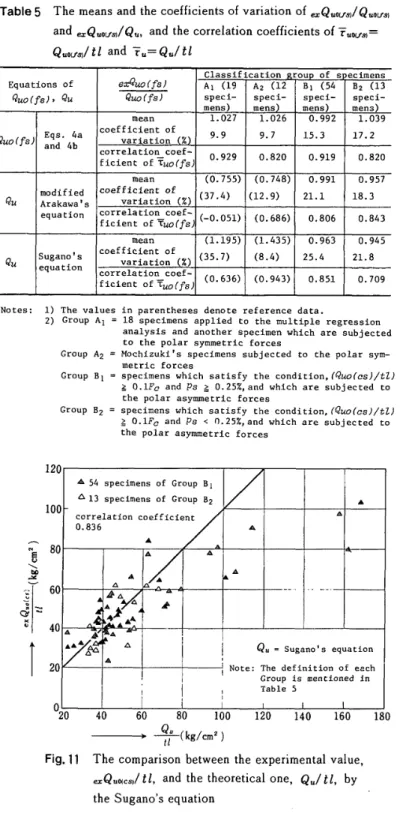
tlThe
comparisonbetween
the
experimental value, e=Q.qe.b!tl, and the theoretical one,Q.ltl,
by
the
Sugano's
equationNII-Electronic Library Service
Group
B
than
the
other empirical expressions.6.
Conclusion
By
usingthe
experimentaldata
ofthe
98
specimens,it
is
proved
that
the
semi-theoTetical expressionsderived
in
this
paper
can estimateniore
adequately
the
experimental
lateral
shear
capacities
of shear walls whoselateral
shearcapacity
is
dominated
by
the
shearfailure
ofthe
end of edge column$ or edgebeams
than
the
Sugano's
empirical,expression and
the
modifiedA:akawa's
one
regardless
of
leading
condition.
'
References
1)
S.
Sugano:
Sunimaries
ofTechnical
Papers
ofAnnual
Meeting
ofAfchitectural
Institute
ofJapan
(A.I.J,
),
ecL
1973,
pp.1305-1306
(in
Japanese).
2)
M.
Hirosawa,
T.
Akiyamaand
M.
Shiraishi
:
Summaries
ofTechnical
Papers
ofAnnual
Meeting
ofA.I.J..Ogt.
1975,
pp.
1173-1174
(in'
Japanese).
3)
M,
Yamada/
Gihod6
Publishing
Co.
LTD.,
Aug.1976;
pp.113-]l4
(in
Japanese).
4)
S.
Mochizuki
/On
Ultimate
Shear
Strength
ofReinforced
Cencrete
Shear
Walls-Bearing
Strength
Contrelled
by
Shear
Failure
ofSurrounding
Frame-,
Trans.
ofA.I.J.,
No.306,
Aug.
1981,
pp,40-50
{in
Japanese).
.
M,.
Tomii,
T.
Sueoka
andH.
Hiralshi
:Elastic
Analysis
ofFramedSltear
Warts
by
Assuming
theirInfilledPanel
Walls
tobe
5)
45-Degree
OrthetTopic
Plates
Part1
ancl2.
Trans.
ofA.I.J.,
No.
28e,
June
1979,
pp.
101-109,
No.
284,
OcL
1979,
pp.
51-60
"n
English).
6)
M,
Tomii
andF.
Esaki/
Surltmaries
ofTechnical
Papers
ofAnnual
Meeting
ofA.LJ.,
Sep.
i980,
pp.1575-1576
(in
Japanese).
.References
df
the
Shear
Walls
Subjected
toPolar
Symrnetric
Loads
:
(All
in
Japanese}
IA)
M.
Tomii
andY.
Osaki/Trans.
ofA.LJ.,
No.51.
Sep.
1955,
pp.96-105.
No,52,
March
19.56,
pp.68-78,
2A)
M.
Tornii:Trans.
ofA.I.J.,
No.60,
Oct.
1958,
pp.389-392.
,
3A)
M.
Tomii,Trans.
o,fA.LJ.,
No.89.
Sep.
1963,
pp.164.
M.
Tomii,
T.
Kei,
T.
Yarnaguchi
andH.
Yamamoto:
Reports
ofChugoku-Kyushu-Chapter
ofA.I.J.,
Feb.
I97.8,
4A)
'
pp.179-182.
5A)
M.
Yamada,
H.
Kawamura
andA.
Inada:
Reports
ofKinki-Chapter
efA.I.J.,
May
1978,
pp.125-128,
6A)
S.
Mochizuki
andS,
Matsuo
/Summa[ies
ofTechnica]
Papers
ofAnnual
Meeting
efA.
I.J,
,Sep.
1978,
pp.1637-l638.
7A)
S.
Mochizuki
andS.
Kawabe
,Summaries
ofTechnicat
Papers
ofAnnual
Meeting
ofA.
I.J.
,
Sep.
1979,
pp.1459-1460.
sA)
S.
Mochlzuki
andY.
Hosaka/
Summaries
ofTechnical
Papers
ofAnnual
Meeting
ofA.
I.J.
,
Sep.
1979,
pp.1473-1474.
gA)
S,
Mochizuki/Trans,
ofA,I.J..
No.291.
May
1980.
pp.1-10.'
10A)
F.
Esaki,
M.
Tomii
an'dT.
Nagai/
Reports
efChugeku-Kyushu-Chapter
ofA.'I.J,,
March
1981,
pp.209-212.
References
ofthe
Shear
Walls
Subjectecl
to
the
Polar
Asymmetric
leads
:
(Al]
in
Japanese
except3B,
4B
and5B)
IB)
H.
Tanabe,
C.
Katsuta
andT.
Azuma/T[ans.
ofA.I.J.,
Apr,
1934,
pp,3e6-319,
2B}
H.
Tanabe,
C.
Katsuta
andT.
Azuma/
Trans.
oiA,I.J.,
Apr.
I935,
pp.326-339.
3B
)
Gerard
D.
Galletly
aadRobert
J.
Hansen
/Behavior
ofReinforced
Concrete
Shear
Walts
UnderStatic
Loacl,
Massachusetts
Institute
ofTechnology,
Departrnent
ofCiyil
andSanltary
EnginEering,
Aug.
Igs2.
,
4B)
Jack
R.
Benjamin
andHarry
A,
Williams:
Investigation
of shearWaLls,
Department
ofCivil
Engineering,
Stanferd
University
Apr,
1952-Dec.
1956,
/The
Behavier
ofOne-Story
Reinforced
Concrete
Shear
Walls,
Journal
ofthe
Structural
Division
ef theAmerican
Society
ofCivil
Engineering,
V61.83,
No.ST3,
May]957,
pp.1254-1-1254-49.
5B)
Joseph
Antebi,
Senel
Utku
andR6beTt
J.
Han$en:
The
Response
ofShear
Walls
toDynarnic
Loads,
Massachusettes
Institute
ofTechnelogy,
Department
ofCivil
andSanitary
Engineering,
Aug.
1960.
6B)
T.
Naka
andK.
Ryo:
Trans.
ofA.I.'J.,
No.69,
Oct.
1961,
pp.477-480.
7B)
S.
Sugago:
Summa[ies
ofTechnical
Papers
ofAnnuaL
Meeting
ofA.I.J.,
Sep.
1970,
pp.749-750,
TL
Aoyagi,
S.
Furui
andF.
Esaki/
Sumrnaries
ofTechnical
Papers
ofAnnua]
Meeting
pf
A.I,J,,
Oct.
1974,
8B)
'
pp.1381-1384.
'
gB}
T.
Achiyoshi,
Y.
Ueda,
N.
Qgawa,
Y.
Takashima
andH.
Takeda
:Reports
ofHekkaido-Chapter
ofA.I.J.,
Match
1977,
'