Synchronization of Two Chaotic Circuits Coupled via Mutual Inductance
Ayana SHIMADA Hironori KUMENO Yoko UWATE Yoshifumi NISHIO (Tokushima University)
1. Introduction
Synchronization phenomenon is one of the fundamen- tal phenomena in nature. Especially, chaos synchroniza- tion phenomena in nonlinear circuits have been studied in many fields. Thus, it is thought that investigations of the synchronization phenomena will be important in the future.
In this study, we investigate synchronization phenom- ena in two coupled chaotic circuits via mutual inductance.
We observe some interesting synchronization phenomena.
2. Circuit model
C
L1
L2
−r
i
2L1
i
1−r
C L2
v
2v
1I1
I2
Figure 1:
Circuit model.The circuit model used in this study is shown in Fig. 1.
In this circuit, two identical chaotic circuits are coupled via mutual inductance.
First, we approximate the i−v characteristics of the nonlinear resistor consisting of diodes by the following function.
vd(ik) =√9
rdik. (1)
By changing the variables and parameters, Ik=a
p
C/L1xk, ik=
p
C/L1yk, vk=azk, α=
p
L1/L2, β=
p
C/L1, γ=M/L1, t=√
L1Cτ , “·” =d/dτ ,
³
wherea= 8
q
rd
p
C/L1´
(2)the circuit equations are normalized as
˙ x1= 1
1−γ2{β(x1+y1)−z1}
− γ
1−γ2{β(x2+y2)−z2}
˙
y1=α{β(x1+y1)−z1−f(y1)}
˙
z1=x1+y1
(3)
˙
x2=− γ
1−γ2{β(x1+y1)−z1}
+ 1
1−γ2{β(x2+y2)−z2}
˙
y2=α{β(x2+y2)−z2−f(y2)}
˙
z2=x2+y2
(4)
3. Simulation Results
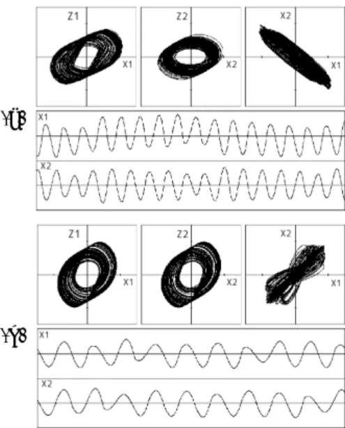
We carry out computer calculations for the two chaotic circuits coupled via mutual inductance. We observe var- ious synchronization phenomena. Figure 2 shows the ob- served attractors, phase differences and time waveform for the parameters (a):α= 24.0,β= 0.20 andγ= 0.60, (b):
α= 24.0, β= 0.30 and γ = 0.05. In Fig. 2(a), the two chaotic circuits are synchronized at the opposite-phase.
Whereas, the two chaotic circuits are synchronized at the in-phase as shown in Fig. 2(b). In the coupled circuits, the two circuits are synchronized at the opposite-phase whenβ, which determines chaotic characteristics of each circuit, is small. While, the two circuits are synchronized at the in-phase whenβis large.
(a)
(b)
Figure 2:
Opposite-phase synchronization and in-phase syn- chronization are observed for the values ofβ which are small values and large values, respectively. α= 24.0. (a)β = 0.20 andγ= 0.60. (b)β= 0.30 andγ= 0.05.4. Conclusions
In this study, we investigated the synchronization phe- nomena in chaotic circuits coupled via mutual inductance.
By carrying out computer calculations for the circuits, we confirmed various kinds of synchronization phenomena.
In-phase synchronization and opposite-phase synchroniza- tion can be observed for different parameters.
References
[1] Y. Nishio and A. Ushida, “Spatio-Temporal Chaos in Simple Coupled Chaotic Circuits,” IEEE Transactions on Circuits and Systems I, vol. 42, no. 10, pp. 678-686, Oct.
1995.
平成22年度電気関係学会四国支部連合大会