Analysis of Environmentally Assisted Cracking Based on . Stress· Dependent Intergranular Corrosion Concept
Katsuyuki Tokimasa
1and Mitsuo Miyahara
2Abstract
This paper describes some results of the authors' recent study on the analysis of SSRT (Slow Strain Rate Test) based on the stress dependent IGC Ontergranular Corrosion) concept.
This paper also discusses how quantitative information can be obtained from SSRT results, especially concerning the intergranular corrosion rate and the crack propagation rate, by which the SCC life in service can be predicted. Finally, the practical procedures are proposed to determine the stress dependency of I GC of materials by SSRT.
1. Introduction
Resistance against IGA Ontergranular Attack) or IGCIIGSCC Ontergranular
·CorrosionlIntergranular SCC) is one of the most important material properties relevant to Pressurized Water Reactor plants. Especially, for steam generator tubing materials, improvements in resistance against IGCIIGSCC under both primary and secondary water environments have been made for many years (1-4). The material MA600 (15%Cr-75%Ni-9%Fe, Mill Annealed) was initially adopted as the steam generator tubing material of the Japanese domestic plants, though there were some experiences ofIGCIIGSCC in foreign plants. In order to improve resistance against IGCIIGSCC, a new thermal treatment (Tr) was developed and followed by the recent development of TT690 (30%Cr-60%Ni-9%Fe) (5,6),
In the case of the development of Tr600 and TT690, the accelerated SCC testing was employed (7) and it was shown qualitatively that TT 690 is superior to MA600 and TT600.
However, there was little quantitative information on the corrosion rate and the crack propagation rate, by which the SCC life under the condition in service can be predicted.
The authors have been studying the effect of materials, stress and environment on damage initiation and its growth phenomenon in the simulated PWR water for the purpose of establishing a life prediction model and clarifying the parameters needed in that model (1-3,8-10).
The final goal of their work is to predict the life of plant components based on accelerated SCC test results. Until now they have proposed a simplified life prediction model based on the stress-dependent IGC concept (10).
The main differences in conditions between real plants and accelerated SCC tests are the stress level applied and the test environment. In the plants the stress level is generally low and the stress intensity factor K at the crack tip is almost always under Krsee. On the other hand, in accelerated SCC tests, the stress level is so high that K exceeds Krsee from early
1. Department of Mechanical Engineering, Kinki University, Wakayama 649-6493, Japan 2. Corporate R&D Laboratories, Sumitomo Metal Industries, Ltd., Amagasaki 66O-0891,Japan
80 Memoirs of The School of B.O.S.T. of Kinki University No. 8 (2001)
stage of the damage growth. This means that it is more important to know the IGC growth rate than Krscc for the plant life prediction, because IGC stage occupies the main part of the plant life. In the previous paper, in order to get quantitative information on IGC crack growth rate of materials, the results of such accelerated SCC tests as RUB <Reversed U -bend test) and constant load test were analyzed based on the life prediction model proposed by the authors. As the results, the stress dependency ofIGC growth rate was determined for MA600 and TI600 in primary and secondary caustic environments (10).
Recently SSRT (Slow Strain Rate Test) has been frequently used as one of the most convenient accelerated SCC testings. This is probably because SSRT has a major advantage of enabling application of much higher stress to a specimen during shorter testing period than RUB test and constant load test. However, it has not been clarified how the service life of the structural components can be estimated by using the SSRT results.
In the present paper, the analysis of SSRT is conducted based on the stress-dependent IGC concept in order to clarify how useful and quantitative information for service life evaluation can be obtained from SSRT. As the results, it is found that the stress dependency of IGC growth rate of materials tested can be determined by SSRT and the practical testing procedures for that are recommended.
2. The SSRT lifetime analysis based on the stress dependent IGC concept In the stress-dependent IGC concept, the stress corrosion cracking process is divided into IGC and IGSCC processes as shown in Fig.1 and the several assumptions are settled. The first, it is assumed that IGSCC growth rate is much higher than IGC growth rate so that IGSCC lifetime t IGSCC can be neglected compared with IGC lifetime t IGC •
Secondly, it is assumed that IGC process is thermally activated and the IGC growth rate is generally expressed by the following equation,
da
=
a exp(Qo - qoa) (1)dt 0 RT
where ao is a constant, Qo and qo are activation energy and activation volume respectively, R is gas constant and T is an absolute temperature.
Under a given environment and temperature, Vo = ao exp(-Qo / RT) and q = qo / RT are constant. Then, the equation (1) can be expressed as follows:
- = da Va exp(qa).
dt
Furthermore, it is assumed that IGSCC process is controlled by the stress intensity factor K at the crack tip.
These assumptions are schematically depicted as shown in Fig. 1 and Fig.2. The transition from IGC to IGSCC occurs when
1
(K )2
a ~ a
1h
= -
ISCC1( 17a ,
IGSCC
process\
Fig.l Simplified IGCIIGSCC process (Applied stress is constant) t r
=
t IGC + t IGSCC== tlGC (tIGC ~ tIGSCC)
(f : increase
IGSCC process
~---~---~ K
KISCC
Fig.2 Proposed model of IGCIIGSCC process (da / dt increases with the increase of applied stress at K below K ISCC
where 17 is a constant determined by crack geometry and (J" is the stress applied to a SSRT specimen.
In SSRT the specimen is loaded at the constant $train rate and the stress in the specimen grows and varies with time corresponding to the deformation characteristics of the material tested. It is assumed that no creep deformation and no dynamic strain-aging phenomenon occur, and that the stress response during SSRT is not affected by the IGC growth.
Considering these, the depth of IGC at time t after SSRT initiation is given by integrating the equation (2) from t=O to t=t as in the following:
I
a
=
fVa exp(qa)dt , o82 Memoirs of The School of B.O.S. T. of Kinki University No.8 (2001)
=
d
q {exp(qa,) -I}~ ';q ~xp(qO"
,)-1)
+
~o ~xp(qa,)
- exp(qa y)} (a, > a y)&fIq
(5)
where
8
is the constant strain rate in SSRT, (J t is the stress at time t, a is the depth of IGC, E is the elastic constant, (J y is the yield strength and n is the strain hardening coefficient, and the stress vs. strain curve of the material is given by the equation (6) in the bi-linear form as shown in Fig.3:a y a-ay
& = - + - - E ' n
a E
(6-1) (6-2) The SSRT lifetime is determined by the criterion given by the equation (7) when IGSCC growth precedes the ductile fracture of the specimen:
(7) whereas another criterion is needed in the case that the ductile fracture may precede the fracture by IGSCC. This criterion is expressed by the equation (8):
(8)
where fj/ is the reduction of area obtained by the tensile test and B f is the fracture strain.
The lifetime determined by the equation (7) is expressed as t lGC , whereas the lifetime by the equation (8) as tE and the depth ofIGC at tE as acr '
f f
The flow chart of calculation process of the SSRT lifetime is shown in Fig.4.
Stress Bi-linear approximation
2:
,a, + n (, - a,/E)/\
Stress-strain curve obtained by test
W--_ _ _ _ _ _ ~ _ _ _ _ _ ~ Strain
Fig.3 Bi-linear approximation of the stress versus strain relationship of the material tested
NO
INPUT Va. q. ~
Calculate:
d=
s
t). ti"a.
tlth' £.1(= -in(l-y,»
NO
SSRT life (tIGCor tu)
is determined. . . . - - - - '
Fig.4 Flow chart of calculation process
3. The Results of SSRT lifetime analysis
The SSRT lifetime ofMA600 in simulated PWR primary water environment was analyzed by the procedure described above. The units of the variables and constants used in the equation (1) to (8) are as follows:
a: fOIl t : hr Va : fOIl / hr q: MPa-1
0' ,E , n: MPa K1SCC :MPaFm .
The stress dependency of IGC growth rate of MA600 in the simulated primary water at 360°C given by the following equation(lO) was used in the analysis:
da dt = O.00291exp(O.00640'). (9)
In the present paper the effects of strain rate and material strength on the SSRT lifetime were studied.
3.1 Effect of strain rate
For simplicity of calculation, the following material strength parameters are used for evaluation of the effect of strain rate:
E = 200,000MPa n=500MPa O'y == 150MPa, If == 0.64
K1SCC == 13MPaJ;
(10)
84 Memoirs of The School of B.O.S. T. of Kinki University No. 8 (2001)
Fig.5 shows an example of the calculated IGC growth behavior during SSRT conducted at the strain rate of 10-7 lIsec. As found in the figure the IGC growth rate is not constant during SSRT. The average IGC growth rate (da / dt) ave increases with the increase of the testing period and reaches the maximum when t = t IGC ' that is, the specimen fractures.
It is usually conducted in treatment of SSRT data to calculate the average crack growth rate from the maximum intergranular crack length measured in the fracture surtace of the specimen as the results of SSRT. In the present analysis the average crack growth rate is also calculated by the following equation, which enables us to compare the present analysis with the previously reported SSRT data:
(da) a
dt ave ==
t
= ~
{exp( qat) -1 }etEq
= _
Vo {exp(qay)-1}
etEq
+ .Vo {exp(qat) - exp(qay)}
etnq
(11)
The results on the effect of strain rate on the SSRT life are summarized in Fig.6. From these, the followings are noted:
(1) The SSRT life increases with the decrease of strain rate.
(2) In SSRT conducted at higher strain rate, the ductile failure tends to precede IGSCC.
(3) The average IGC growth rate increases during SSRT and its increasing rate is larger at higher strain rate test.
fJy = 150 MPa n = 500 MPa
~ = 10-7/sec
. 200r---.----.---.----~--_rr--~
E
3- alh=1l6.5,umCI:S
..c::
fr
100'0 U 8
1000 2000 3000
Time t (hours)
Fig.5 An example of the calculated IGC growth behavior during SSRT conducted at the strain rate 10-7 1/sec
8
U ~/£
tEr =10-6/= 284 hours, asec er = 16 . 7 ,u m~ / £ =1O-7/sec
~ 10-8 tlGc = 2 542 hours
.§ a'h=116.5,um
~
e
~ ~ tlGC
=
14 028 hoursa1h = 265 . 4 ,u m 10-9 1 - - 1 - . . . . - . J ' - - . - J - 1 - - - L - - ' - - - ' - - - ' - - - ' - - ' - - - - ' - - ' - - - ' - - - ' - - - - '
o 5000 10000 15000
Time t (hours)
Fig.6 The calculated results on the effect of strain rate 8 on the SSRT life
3.2 Effect of yield strength and strain hardening coefficient
Fig.7 and Fig.S show the results on the effect of a y and n on the SSRT life. The analysis was conducted at 8 = 10-7 / sec and the material parameters except for a y or n are the same as shown in the equation (S). The effect of a y was analyzed for n =500 MPa and the effect of n was analyzed for a y =150 MPa. The results obtained are summarized below.
(1) The decrease of a y and n tends to increase the SSRT life, decrease the value of (da/ dt}ave and increase the strain at the specimen fracture (=tIGC x &).
(2) Each of the calculated SSRT lives in the present study is determined by IGSCC, but the lower a y and n tend to lead the specimen failure at the larger strain. This suggests that the factors, which may reduce a y and n, will make the ductile failure precede IGSCC in SSRT tested specimen.
(3) It should be noted that, when the materials with equal resistance against IGA and with different a y and n are tested by SSRT, the materials with higher a y and
n tend to have shorter SSRT life than those with lower a y and n.
(4) It should be aloo noted that the material with lower a y and n may exhibit longer SSRT life than the material with better resistance against IGA and higher a y and
n.
The last two items listed above suggest the limitation of the conventional treatment of the SSRT data. That is, it can be said conclusively that the SSRT method is not useful and not reliable as long as the conventional way of data treatment is conducted especially in case of testing the materials with different strength and deformation properties.
86 Memoirs of The School of B.O.S. T. of Kinki University No.8 (2001)
~ ...
! 8 10-8
n=500MPa
- - O'y == 150 MPa 250 350 10-9 OL---'--l....LOO-,-O - . . 1 - - -
2 0.J....
00- - - - L . . -
3--'000 Time t (hours)
Fig.7 The calculated results on the effect of yield strength G'y on the SSRT life (i = lo-71/sec)
] ...
! 8 10-8
O'y == 150 MPa tlCC = 1 059 ours
,. + ,+
,/ , / 1 469 hours
,l ~
"
,~," ,,"
, ,
,l/"
, "
,~/ - - n=500 MPa
,~~
1000 1500 10-' '"--'---'---'---'---'---'
o 1000 2000 3000
Time t (hours)
Fig.8 The calculated results on the effect of strain hardening coefficient n on the SSRT life (i
=
lO-71/sec)4. Evaluation of the literature data of SSRT on MA600
In order to examine whether or not the proposed life prediction model based on the stress-dependent IGC concept can evaluate the previously reported SSRT data, the analysis was conducted on the CERT (Constant Elongation Rate Test) data on MA600 in the simulated PWR primruy water environment reported by J.-M.Boursier et al.(ll) The CERT is considered the same test as the SSRT.
Table 1 shows the main properties of three different MA600 tubes tested and the results of RUB tests, constant load tests and CERT on them. Fig.9 shows an example of the crack depth distribution of tube @ measured after CERT. The values of Slow CGR (crack growth rate) and Rapid CGR were determined based on the measured crack distribution. Fig. 10 shows the effect of strain rate on Slow CGR and Rapid CGR obtained on the same material in Fig.9.
Table 1 Main characteristics of Alloy 600 tubings studied by J. -M.Boursier et al. and their susceptibility determined with the reversed V-bend (RUB) tests, the constant load tests and CERT (360°C primary water, 1000 ppmB3+ 2 ppmLi+ , 4 bar overpressure of hydrogen at 125°C) 11)
(a)
Tubes Carbon content MA temperature ASTM Yield stress at 350°C
studied (%) CC) grain size (Mpa)
CD
0.033 1070 8 (22,urn) 280®
0.026 980 10 (ll,um) 330@ 0.030 915 10 (ll,urn) 290
(b)
RUB tests Constant load tests CERT*
Tubes Time to cracking Nominal stress Time to cracking Crack depth
studied (hr) (Mpa) (hr) (,urn )
CD
>36000 10®
<1000 684 822 100@ <500 570 900 325
* Strain rate: 5 x 10⁻⁸ 1lsec, 50,urn electro polished tube Test duration is not clearly described.
1 0 0 0 0 . . - - - ,
.£l s:: 1 0 0 0 1 - - - ;
!! «I
~ Slow CGR: 0.12 .urn/h
.c:: 100 I---\~---_j
"'C ~
-s «I
.S;
~ en u ~
.... u o ..0 til 8 ;::I
Z
101---~---j
100 200 300 400 500
~ : Crack depth trace (,urn)
Fig.9 The number of cracks with a trace depth greater than £, , as a function of
.e
(tube @, CERTat 5 x 10⁻⁸ lisee, 360°C primary water, 4 bar overpressure of hydrogen at 125°C) 11)
88 'Memoirs of The School of B.O.S.T. of Kinki University No.8 (2001)
~ ro~---~
e
RapidC~ ~3 ~O.58
S 1
~
O.OJ10'-_·---lOL..-a-'---lO.L--7---:-'.1O-, Strain rate (l/sed
Fig.l0 Evolution of crack growth rate as a function of strain rate (tube @, CERT at
5xlO-81/sec,360°C primary water, 4 bar overpressure of hydrogen at 125°C) 11)
The constant-load -test life and (da / dt) ave at the SSRT specimen fracture were evaluated by the life prediction model based on the stress-dependent IGC concept. The material properties as shown in the equation (12) were used in the analysis for tube @:
E == 200000 MPa ) n
=
2777 MPa, (J" y=
290 MPa .K[SCC = 13 MParm
(12)
The value of (J' y is given in Table 1 and the value of n . is assumed the same as that of tube
@ shown in Fig. II.
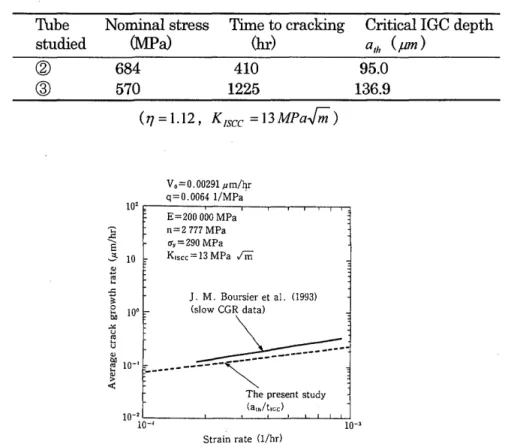
Table 2 shows the estimated values of the constant-load-test life and ath , and Fig.12 shows the estimated values of (da / dt) ave at the SSRT specimen fracture compared with the reported value of Slow CGR. The satisfact01:y agreements are obtained between the estimation and the experimental values in both cases.
850 - - - - , 740 - - - -. - - - - , ® '
~~~ -_ -=--=--=--=- - - I : :
~ I(D: I
I
6 " : I
: : : <D n == 2 777 MPa I : : @n==2037MPa
I ' I
, I ,
I I J
I I I
I I 1
I : 1
.1 /.
300.1
300i.
Time~h)
Fig.lI Change in stress during CERT at 5xIO-81/sec (tube @, 360°C primary water, 4 bar overpressure of hydrogen at 125°C) reported in the literature 11)
Table 2 Estimated values of the constant-load -test lives and a th of tubes (The test results of tubes @ and
®
are shown in Table 1 11»Thbe studied
@
®
Nominal stress Time to cracking
(lVlPa) (hr)
684 410
570 1225
(17=1.12, K1scc = 13 MPa.J;)
Vo=0.00291 tlm/hr q=0.0064 l/MPa·
102 "l: ---r---,--...--.--~--r-,...,
E=200 000 MPa ]
E
3 10
~ ~
n=2777MPa O"y=290 MPa K,scc = 13 MPa 1m
~ J. M. Boursier et al. (1993)
iIO'C (~.
'" 10-1 F.. ----~ -:
~
---
<t:
The present study (alhItIGC)
Strain rate (l/hrl
Critical IGC depth ath (pm)
95.0 136.9
Fig.12 Comparison of the estimated values of slow CGR based on the stress dependent IGC concept with the values reported by}.-M.Boursier et al. 11)
5. Evaluation of the stress dependency ofIGC by SSRT
The value of (da / dt)ave which is usually obtained by SSRT greatly depends on the material strength parameters, the strain rate adopted in SSRT and time t. This fact indicates that the daldt data obtained from SSRT are no more quantitative information about the material resistance against SCC. It is more important to evaluate the stress dependency ofIGC, that is, to determine the value of q and Vo.
In the recent paper (10) one of the authors and his colleague showed possibility that the stress dependency of IGC is obtained by conducting well controlled SSRT, where the stress
a and the length ofIGC during SSRT need to be monitored and recorded.
From the equation (5) the following relationship between fla and flO' during SSRTcan be derived as the equation (13):
90 Memoirs of The School of B.O.S. T. of Kinki University No. 8 (2001)
In(:;)
=qu
+In( ;~) whenu'; u,) '.
In(:; )=qu+ln(;~) whenu>u,
(13)
The constants q and Vo in this equation can be determined because f1a / ~O' vs. 0'
relationship can be obtained in the well controlled SSRT and the values of
s,
E and nare known. However, at present, it is very difficult to measure and monitor the IGC growth during SSRT, though some trials have been done (12).
In the present paper another more practical procedure is proposed. By using the equation (11), the following two equations are obtained if we can get the data on the average daJdt and the stress (> 0' y) at two different times t1 and t2 during SSRT conducted at the same strain rate:
(da)
=~
{exp( qO" y) -I}
+~
{exp( qO" I) - exp( qO" y)} ,dt ave! ctlEq ctl nq
(14-1)
(da) =~~Xp(qO"y)-1}+~~xp(q0"2)-exp(qO"y)}.
dt ave 2 ct2Eq ct2nq
(14-2)
Subscript 1 and 2 show the values obtained at tl and t2 respectively. In the above equations the unknown quantities are q and Vo ' and so these two can be determined.
Compared with the former method that needs monitoring IGC growth during SSRT, the latter method that needs at least two SSRT specimens is very easy to apply' to the analysis of SSRT data because it only requires the measurement of the average daJdt at two different times at the same strain rate.
It may be possible to obtain q and Vo based on the average daJdt and time t at two different strain rates
s
1 ands
2 by the same procedure by using the following two equations:(da)
= .Vo~xp(qO"y) -l}+~~xp(qO"I)
- exp(qO"y)}dt ave 3 cJtEq cltnq
(15-1)
(da) =~~Xp(qO"y) -1}+~~xp(q0"2)-exp(qO"y)}
.dt ave4 c2tEq c2tnq
(15-2)
In Fig. 13 the procedure to determine the value of q and Vo is shown schematically.
In the equations (14), (15) and Fig.13 it is assumed that 0' y 'and n are independent on the strain rate. Since the stress vs. strain relationship during SSRT can be monitored, the measured values of 0' y and n should be used. And it is also recommended to interrupt SSRT and observe I GC or crack depth distribution before the specimen fractures, which gives
-
~..c:
' -S 3-
> 0
10-2
10-3
Case 1 : i
=
10-7 l/seet1 = 1 004 hrs, 0'1 = 330.3 MPa, (da/ dt) avel =3.966 x 10⁻⁹ mm/see Case 2 : i
=
10-7 l/see~=2 004 hrs, 0'2=510.3 MPa, (da/dt)aVe2=8.265 x 10-9 mm/see Case 3: E = 10-6 l/see
t3 = 284 hrs, 0'3 = 660.8 MPa.
(da/ dt) ave3 = 1. 632 X 10-8 mm/see
(fy = 150 MPa n = 500 MPa
10-4 ' - - - - L - . - - ' - . l - J . . J ... .:....1 _'---'---L..-I....L...L.J....U...J ... '---J.---L..-I-J-I-L.U
10-4 10-3 10-2 10-1
q (MPa-l )
Fig.13 Calculation of q and Vo based on different sets of experimental data of t, (Y and (da / dt) ave at t, where it is assumed that ( j y and n take the same value in all the cases shown in the figure
us more accurate information on IGC growth rate than conducting SSRT until the specimen fractures.
6. Conclusion
To get more quantitative information on the material resistance against IGCIIGSCC from SRRT, the SRRT life analysis was done based on the stress dependent IGC concept. As the results, it is found that the average da/dt data usually obtained from SSRT are no more quantitative information about the material resistance against IGCIIGSCC. Then, the two practical procedures were proposed to evaluate the stress dependency of IGC by conducting SSRT. Among the two are recommended the procedure in which the average da/dt data obtained at two different testing conditions are used and analyzed based on the stress-dependent IGC concept.
92 Memoirs of The School of B.O.S. T. of Kinki University No. 8 (2001)
References
(1) H.Nagano, K.Thkimasa, K.Yamanaka and H.Miyuki, Effects of environmental and material factors on the intergranular at;tak of Alloy 600, EPRI Workshop on Remedical Actions to Secondary Side Intergranular Corrosion, 1985, Baltimore, USA
(2) K.Yamanaka, K.Thkimasa, H.Miyuki and H.Nagano, IGA behavior and mechanism of nickel based alloys, EPRI Meeting on Intergranular Corrosion and Primary Water Intergranular Stress Corrosion Cracking Mechanism, 1987, Pittsburgh, USA (3) H.Nagano, K.Yamanaka, K.Thkimasa and H.Miyuki, Intergranular attak behavior and
mechanisms for nickel base alloys at elevated temperature, Proceedings of the First International Conference on Environment-Induced Cracking of Metals, NACE, 1988, 407-413
(4) M.Kowaka, H.Nagano, T.Kudo and YOkada, Effect of heat treatment on the susceptibility to stress corrosin craking of Alloy 600, Nuclear Technology, 55 (1981) 394-404
(5) T.Yonezawa, K:Onimura, N.Sasaguri, T.Kusakabe, H.Nagano, K.Yamanaka, T.Minami and M.Inoue, Evaluation of corrosion resitance of Alloy 690, EPRI Workshop on Thermally Treated Alloy 690 for Tubes in Nuclear Steam Generators, 1985, Pittsburgh, USA
(6) H.Nagano, K.Yamanaka, K.Kobayashi and M.Inoue, Development and manufacturing system of Alloy 690 tubing for PWR steam generators, The Sumitomo Search, 40
(1989) 57-70
(7) K.Yamanaka, T.Minami, K.Thkimasa and H.Nagano, Intergranular corrosin test method for nickel-based Alloy 690, J. Japan Inst. Metals, 49 (1985) 125-133
(8) H.Nagano, K.Thkimasa, K.Tanaka and H.Tsuge, Evaluation of SCC resistance of Alloy 600 in high temperature pressurized water environment by the high stress ratio cyclic crack growth tests, Tetsu-to-Hagane, 74 (1988) 527-534
(9) N.Konda, K.Thyama, K.Yamanaka and K.Tokimasa, Environmental effects on the crack growth properties of Alloy 600, Int. J. Pres. Yes. & Piping, 52 (1992) 217-226
(10) N.Konda, K.Thkimasa, K.Yamanaka and M.Inoue, Dynamic SCC threshold evaluation and life prediction for SG tubing materials, Draft Proceedings of International Symposium on Plant Aging and Life Prediction of Corrodible Structures, Paper No. A II 16, 1995, Sapporo, Japan
(11) J.-M.Boursier, O.de Bouvier, J.-M.Gras, D.Noel R.Rios and F.Vaillant, SCC of Alloy 600 in high temperature water: a study of mechanisms, Corrosion-Deformation Interactions CDI'92, 1992, Fontainbleau, France.
(12) S.Suzuki and T.Shoji, SCC initiation and propagation study of SUS 304 in high temperature water by ACPD, Draft Proceedings of International Symposium oil Plant Aging and Life Prediction of Corrodible Structures, Paper No. AIII07, 1995, Sapporo, Japan ..
PWR~~~~~~~~~~~r~~seem~~~~·~~7ptA~m~~~a~) JmJf£~*lL~J;tjJ~~~IJnaGsee)~f£~ ~;::.)j-~t,
see
~7J~'I'l'I~ ~f£~5(i':1c~n, lJ""JIGe
~7J~{-'FmJ;ttJ~;::.-(t(1¥TQ ~1&~TQ
=-
~ ,;::.J: 1],see
~TiJllJ~~9';::'1T?=-
~ lJ~~~ Qo*ffi~~j:,
=- (})
J: ? f~see
~TiJllJ(})~ :zjj~SSRT
(Slow Strain Rate Test) ~~f§l#JT~;::.~m L-tc~*~¥a15TQ ~ ~ t~;::.,
SSRT
¥ta;::'J: 1]*,1m.Ji@;~~~J;ttJ-(t(fpl1:~i*~TQ~{~-¥¥t~;::."Jv \'"(