90
Facilities and Radiation Test Methods
Ari Virtanen
*11 University of Jyväskylä, Finland
*Email:
[email protected]Keyword(s): single-event effects (SEE), total ionizing dose (TID), LET, cyclotron, Co-60, RadHard Abstract
This talk gives an overview of methods to test component failures caused by space radiation. First, a short introduction to the reasons such tests are necessary, and recent developments in test methodologies are given.
Then, radiation environment and error effects, most specifically total dose and single-event-effects, are introduced. A more detailed description is given of the physics of different radiation interactions in semiconductors and the requirements they set for test methods. Facilities used worldwide to study radiation effects in electronics are listed, from which two commonly used test facilities are introduced in more detail.
1. Introduction
In the last decades, electronics has evolved very quickly. Since 1970, the number of components per chip has roughly doubled every two years (known as “Moore’s Law” [1]). The introduction of CMOS technology has raised radiation effects in components as an important issue in satellite projects and space missions. At the end of the cold war, the market for radiation hard (RadHard) components crashed and during the 90’s their fabrication practically stopped. The use of “commercial-off-the-shelf” (COTS) components has become more common but requires increased evaluation activities at radiation test sites. Hence, the radiation hardness assurance (RHA) questions and the test methods involved have been a growing issue among the radiation community.
The COTS components are small in physical size, their power consumption is low, the memory capacities are large and processors fast, and they typically represent the latest design. Moreover, their reliability is tested in everyday use and applications. All these properties are useful for satellite electronics, but one concern remains;
their radiation tolerance. In order to determine the radiation durability of components, the space project engineers have turned to nuclear and material physicists, who have broad experience in the interactions of gamma ray and particle radiation. Their experience in using research instruments such as radiation sources and particle accelerators is essential to perform radiation studies of electronics. They also have knowledge of basic research and information available concerning the behavior of energetic gamma rays and ions and their effects in materials. Programs were begun to simulate the space environment at research sites and components were tested to levels exceeding mission requirements. For example, many accelerator laboratories have developed special beam lines and constructed dedicated test areas for component evaluations. In general, particle environments of space projects were predicted with respect to particle mass and energy distributions and with the expected fluxes and fluences. In order to validate this information in tests, concepts such as the stopping power, linear energy transfer, ion penetration range etc. have to be understood. The details of the component structure also define the method of irradiation. For example, higher ion energies result in much deeper ion penetration ranges which enables reverse side irradiation of thinned Integrated Circuits (ICs). This has generated new challenges for the ion source physicists to develop more energetic beams. In order to validate the test also the spectroscopic properties of the beam, like the ion identification, beam purity and energy must be defined in each individual test run. The beam homogeneity, flux and fluence must be calibrated and monitored with high precision during the irradiation [2].
2. Space radiation environments
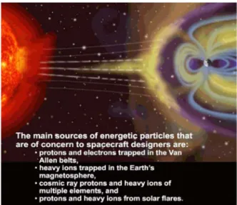
In figure 1, the origins of space radiation and the relevant particle radiation components are given. The most important source of particles, the Sun, emits (besides photons, neutrons and electrons) 70% protons, 28% helium, 1.5% carbon, nitrogen and oxygen ions, and 0.5% heavier elements. Because the Sun cannot create heavier nuclei than oxygen, their existence proves that it is not a first generation star but was formed in a region of more massive stars.
Galactic cosmic rays (GCR) coming from outside of the solar system can have energies up to 10
20eV and are the debris from the novae and supernovae in the Milky Way or other galaxies.
Trapped particles in the two Van Allen belts consist of electrons and protons. According to their particle
abundances the inner belt is known as the proton belt and the outer one the electron belt.
91
Stars with masses of more than eight times that of the Sun are able to create heavy particles such as iron. Iron is the heaviest element, whose abundance in space is significant enough to cause single event effects (SEU) in spacecraft components. In figure 2 the relative abundances of elements in GCR are given.
3. Radiation interactions vs. test methodology
Radiation interacts with the component material primarily by creating electron-hole (e-h) pairs (through ionization) or atomic dislocations. The e-h pairs are the source of total ionizing dose (TID) and single-event effects (SEE). SEEs can be either temporary (soft) or permanent (hard) errors. Atomic dislocations cause displacement damage dose (DDD) effects in the target material.
3.1. Total ionizing dose
The cumulative absorbed ionizing dose in a given material is referred to as the total ionizing dose (TID). It gives a measure of the energy deposited in a medium by ionizing radiation per unit mass; in SI units 1 J/kg = 1 Gy. A more commonly used unit in the radiation community is the rad; 1 Gy = 100 rad,
Electromagnetic radiation primarily induces total ionizing dose effects in electronics. Typically in radiation testing, x-rays and gamma rays have been considered, at energies from a few keV up to several MeV, respectively. There are three primary photon-matter interactions involved: the Photoelectric effect (PE), Compton scattering (CS) and Pair production (PP). Their energy dependence in different materials is illustrated in figure 3. The solid lines correspond to the equal cross sections of neighboring effects. The horizontal dashed line indicates their mutual probability change in silicon (Z=14).
In PE, the photon interacts with a bound electron in an atomic inner orbit. This photoelectron receives the whole photon energy and is ejected from the atom. In CS, the photon interacts with a weakly bound outer orbit electron by transferring part of its energy. This Compton electron then leaves the atom. In PP, the interaction between the photon and the atom yields an electron-positron pair. The threshold energy for PP is 1022 keV, which corresponds to 2m
ec
2.
These secondary electrons, from all of the above mentioned mechanisms, create e-h pairs in the semiconductor material and after recombination processes the leftover low mobility holes become trapped in the dielectric of the component. This accumulated extra charge can finally cause the total dose effect.
Clearly, TID can also arise if the component is exposed to energetic electrons directly.
Fig. 6. Space radiation components (
NASA MSFC)
.Fig. 8. Cross sections of the three photon interactions in different materials as a function of photon energy. After [6].
Fig. 7. Relative flux of particles in space as a function of atomic number [4,5].
92
A typical test method for TID is to use a radioactive cobalt-60 source. Cobalt-60 has two gamma energies of 1.17 and 1.33 MeV. From figure 3 one can see that for these gamma rays in silicon CS is the dominating interaction mechanism (see the dashed vertical line at the mean energy of 1.25 MeV). The use of cobalt-60 sources is a cost-effective test method and the dosimetry is relatively simple. In addition, the dose rate can be controlled by adjusting the distance between the source and the device under test, DUT. For lower energy photons x-ray tubes can also be used.
Another test method in TID testing is to use electron accelerators [7]. These accelerators are expensive and their use is quite costly, especially if high doses at low dose rates are needed. The dosimetry is also more complicated than with radioactive sources. Due to the low penetration of electrons this is not favored as a test method (except for studies of solar cells). On the other hand, the radiation from accelerator-based sources can be controlled, which makes the operation of the source flexible and more secure.
3.2. Single event effects
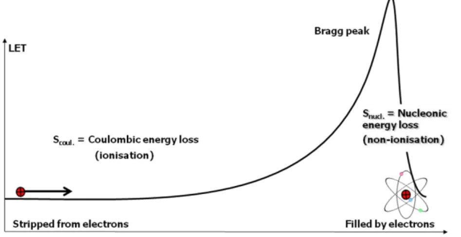
When an energetic heavy ion traverses a medium at a velocity greater than the Bohr velocity, it loses electrons and becomes positively charged. This is described in figure 4.
While traveling in silicon the ion loses energy via Coulomb interactions with the target electrons and an ionization column is formed. This electronic energy loss is typically considered to correspond to the Linear Energy Transfer, LET. It reaches a maximum at the Bragg peak, where the ion fills its orbitals with electrons captured from the surrounding target atoms. Once becoming a neutral atom it can approach closer to the target nuclei and rapidly slows down via nucleonic interactions. A term, which obeys Bragg curve behavior, is stopping power S (or stopping force). Stopping power is the sum of coulombic and nucleonic terms, i.e. S = S
coul+ S
nucl= LET + NIEL (see figure 4). NIEL is an acronym for non-ionising energy loss and is the cause for DDDs in crystalline materials, such as silicon. The terms LET and NIEL are commonly used terms within the space community. LET can be given in units of energy per unit length
[MeV/μm], but most often the unit[MeV/(mg/cm
2)] is used.
In the SEE test method the error cross section of the component is determined as a function of LET. The principle is shown in figure 5. By increasing the LET and monitoring the SEE cross section the threshold and saturation levels of error creation can be obtained.
In order to compare the radiation responses for different components, the cross section has to be normalized to the total fluence of particles per cm
2. The LET values are varied by changing ions with different masses (actually their atomic number, Z). The variety of LETs should cover the threshold and saturation regions as evenly as possible.
Fig. 4. Bragg curve behavior of the ionizing particle.
Fig. 5. Principle of SEE response characterization.
93
In the laboratory, artificial particle radiation sources, such as Ra-226 (100% α-emitter) and Cf-252 (3%
spontaneous fission with heavy fragments having an average LET of 43 MeV/(mg/cm
2) and T
1/2=2.65 years) are convenient for radiation hardness assurance purposes because of their low price and ease of use. Their disadvantages are the restricted ion energies and species along with limited intensities. Due to these limitations, the use of radioisotope sources for SEE tests is prohibited in the official radiation hardness assurance (RHA) tests by the specifications [8, 9]. These sources are typically used only for trial runs of the setup for the RHA testing. Also, lasers are used for the same purpose, but the specifications for RHA testing against SEEs require particle accelerators or nuclear reactors.
4. Facilities
A compilation of worldwide test facilities, used for RHA testing, is listed in the table of Appendix A. The data are taken from [10]. In the following sections one TID and one SEE test facility are shortly introduced. The TID facility, the ESTEC Co-60 facility, is located in The Netherlands and is operated by European Space Research and Technology Centre (ESTEC) of ESA. The SEE facility, RADEF (Radiation Effects Facility), is operated by the University of Jyväskylä and is located in Jyväskylä, Finland. They are both ESA-accredited facilities and belong to the group of four European Component Irradiation Facilities (ECIF) of ESA.
4.1. ESTEC Co-60 facility
In figure 6 the ESA/ESTEC Co-60 irradiation station is illustrated as an example of a TID facility. The station is loaded with a 2000 Ci (June 2007) Co-60 gamma-ray source. It consists of a large control room and a radiation cell with 14 cable feed-throughs enabling monitoring and control of the experiments under test.
Automated total dose and dose rate setting, monitoring and logging are available via software running on a PC.
This system may also be used for automated monitoring of experiments under test. While irradiating dose rates between 0.5-136.8 rads/min. are easily changed by the use of a rail system installed in the radiation cell. The chamber housing the Co-60 source is shown in figure 7. Part of the rail system can also be seen in the figure.
4.2. RADEF facility
RADEF consists of two separated beam lines, one for heavy ions and another for protons. An overview of the facility is illustrated in figure 8, where both of the beam lines are marked. The proton beam is taken in air through a 200 µm thick tungsten window. The proton dosimetry consists of an ionization chamber at the beam exit, and particle detectors behind the target stage. The ionization chamber enables accurate and real-time monitoring of the beam intensity and the particle detectors are used for the initial beam calibration.
Fig. 6. A sketch illustrating ESTEC Co-60 facility. The distance from the source can be adjusted with a trolley, which includes a fixture for the DUT and the dosimetery system [11].
Fig. 8. An overview of RADEF facility [5].
Fig. 7. ESTEC Co-60 gamma source inside the shielding chamber (photo courtesy by Bob Nickson).
94
In the heavy-ion line the beam homogeneity is obtained by using: (1) a 1 µm thick scattering foil made of tungsten, upstream in the beam line, and (2) x–y wobblers. With this equipment beam homogeneity of better than the required ±10% can be achieved over an area of 4 x 4 cm
2, or even larger if needed. Typically an area of 2 x 2 cm
2is used. The heavy-ion dosimetry is made using four photomultiplier tubes (PMT) equipped with scintillator crystals. The PMT detector assemblies are used in the online monitoring of the beam by adjusting the scintillators on the edge of the beam during the experiment. The detectors provide also energy spectra, thus the beam purity can be assured [2, 5].
4.3. Development of ion cocktails for SEE tests
A high-energy, heavy-ion particle accelerator is a very expensive research tool. In addition, high running costs make its use costly, especially because the price of the test is charged according to the duration of the beam time. In order to keep the project costs low the tests should be performed in as short time as possible. A typical SEE-test campaign includes several different ions and all the calibration procedures have to be repeated for each individual beam. Therefore, fast changing of ion species is crucial in SEE tests. To solve this problem, a mixture of ions known as an ion cocktail, is used.
The operation of an electron-cyclotron-resonance (ECR) type ion source is based on microwave power, which ionises atoms by stripping electrons from their orbits. Several different ion species can be simultaneously fed into the ECR and they can be extracted together. Ions belonging to the same cocktail have almost identical mass-to-charge (m/q) ratios. These cocktail ions accelerate along the same path and in order to separate them the cyclotron is utilised as a mass analyser (note, that m/q ≠ A/q). This is done by shifting the cyclotron RF frequency and/or the trim coils in the extraction. These procedures make the fast beam change possible, but require a combination of both ECR type ion source and cyclotron type accelerator.
Two examples of a set of ion cocktails are depicted in figure 9, where the LET curves for different ions as a function of their penetration depths are given. In the low energy 3.6 MeV/amu cocktail the Bragg peak is located between 10 and 50 µm, except for xenon ions. Xenon impinges on the component at the energy corresponding to the maximum LET and its Bragg curve turns downward immediately after the penetration starts.
It is obvious, that in order to reach the sensitive volume with heavy ions from the RADEF ion cocktail, the component package has to be removed. If the sensitive area is close to the die surface, the low energy cocktail of figure 9 can be used. Unfortunately, today many components and practically all modern memories are assembled with the bond pads in the centre and the lead frame on top of the die. Therefore, the direct, front side irradiation is not possible, but irradiation from the back side is needed. In this case the component must be prepared before the test by thinning it from the back side. Typically thinning is done so that there is about 50µm of silicon left on top of the sensitive volume. The method is reliable, but testing requires a high penetration cocktail. An example of this is the cocktail as shown in right-hand side of figure 9. There the Bragg peaks of all ions are located at or after distances of 50 µm.
As has been shown, active development work is needed to improve the capabilities to perform SEE tests in a more reliable and cost effective way. This becomes more and more important along with the technological evolution, with its approach towards the nano-scale and the increased use of electronics “everywhere”. This will inevitably lead to higher demand for radiation hardness assurance, both by testing with radiation and by design and manufacturing.
Fig. 9. LET curves of low and high energy cocktail ion species. Data calculated with SRIM-2003.26 code.
95
Appendix A
A list of facilities, where radioactive photon sources, particle accelerators or reactors are used. Facilities are in alphabetical order and grouped according to their location and the type of radiation(s).
Europe Country Radiation North America Country Radiation
![Fig. 8. An overview of RADEF facility [5].](https://thumb-ap.123doks.com/thumbv2/123deta/6799883.2227862/4.892.107.563.552.839/fig-overview-radef-facility.webp)

