Doctoral Dissertation
Fabrication of Polystyrene Colloidal Crystal Films by Electrophoretic Deposition
and Structural Color Control
Tran Thi Hoai Giang
September, 2020
Materials Chemistry and Engineering Course
Graduate School of Chemical Sciences and Engineering Hokkaido University
Abstract
Chapter 1
A colloidal crystal is an ordered array of colloid particles. The colloidal crystal film is promising for the different types of photonic materials, such as optical waveguides and sensors, due to its wide range of coloring derived from Bragg diffraction in the visible wavelength region. Colloidal crystal films have been synthesized by the various techniques.
However, the low formation rate of the colloidal crystal films has still been one of the key issues in future industrialization for mass production.
Recently, electrophoretic deposition (EPD) is becoming one of the promising candidates to realize the rapid colloidal crystal film fabrication. The EPD process is a widely used coating process for many industrial applications. This process is characterized by the migration of colloidal particles in a liquid under an electric field, i.e., electrophoresis, and the subsequent deposition onto an electrode. In 2000, the colloidal crystal films made of polystyrene (PS) particles with 200 - 300 nm diameters were fabricated for 30 minutes by the EPD technique. Since then, the research of colloidal crystal films was directed to faster fabrication and size enlargement. Nevertheless, they have still remained in the range between 30 minutes and 2 hours, and several cm2 size, respectively. In this thesis, optimal conditions to fabricate the colloidal crystal films by the EPD technique were explored for the sake of fast and large size fabrication. For this purpose, growth mechanism of the colloidal crystal film was investigated in detail. The sensing applications of the colloidal crystal films were also examined.
Chapter 2
The optimal condition for the EPD colloidal crystal film formation was investigated in detail. The aqueous PS colloidal suspension was not appropriate due to the generation of gas bubbles during the electrolysis and formed only amorphous films. Dialysis and the application of a pulse voltage could avoid the gas bubble generation, however, particle self-assembly was still amorphous. As a suspension for the EPD process, the effectiveness of mixing ethanol (EtOH) and water was confirmed by testing several alcohols as solvents, and explained from the different viewpoints including hydrogen bond, van der Waals dispersion force, and mobility/freedom of PS particles. The higher the EtOH concentration, the better the colloidal crystal film formation. In the investigated range,
the most preferable condition for the EPD colloidal crystal film formation was from the 92.5 vol% EtOH suspension. The substrate withdrawing rate from the suspension also significantly affected the EPD colloidal crystal film fabrication. Too slow and too fast withdrawing rates were not good. The most preferable rate was 3.0 mm/sec. The large area colloidal crystal film formation by the EPD technique was also demonstrated.
Comparable quality of EPD colloidal crystal films fabricated on small area indium tin oxide (ITO)-coated glass (ITO/glass) and large area (over 50 cm2) ITO-coated polyethylene terephthalate (PET) sheet (ITO/PET) substrates was confirmed by the SEM observations and the reflectance spectra. These results demonstrate the advantage of the EPD technique for large scale production of colloidal crystal, considering the fast fabrication rate compared to the other conventional techniques. The growth rate of the colloidal crystal is extremely rapid (within one minute for 900 mm2 area) compared with those of previous papers, such as oil covering and capillary deposition methods (several to hundreds of hours). This process has the potential for high-speed deposition of the colloidal crystalline thin films.
Chapter 3
A growth mechanism of the colloidal crystal films from the concentrated EtOH aqueous suspension was investigated. Closely packed colloidal crystal film was formed within 55 seconds. By the analysis of the reflection spectra and the optical microscope images, the growth mechanism from the colloidal suspension to the colloidal crystal film was found to consist of 4 stages. The 1st stage is a liquid film of the concentrated colloidal suspension on a substrate. By the progress of evaporation, the phase transition from disorder to order to form the non-closely packed colloidal crystal by self-assembly takes place. At the moment of the phase transition, the Bragg’s diffraction peak is detected and the structural color appears. In the 2nd stage, the diffraction peak shifts toward the shorter wavelength direction (blue shift), due to the reduction of the interparticle distance of the non-close packed colloidal crystal. In the end, the closely packed colloidal crystal film is formed.
In the 3rd stage, the liquid film covering on the colloidal crystal film evaporated and iridescence color due to thin-film interference is tentatively observed. In the 4th stage, the colloidal crystal film changes from wet to dry, by the evaporation of the interparticle EtOH aqueous solvent. The structural color changes from green to blue and the diffraction peak wavelength goes down with one more stage. This color change is dominated by the
change of the refractive index of the interparticle medium from the liquid to the air.
Chapter 4
The interparticle space of the colloidal crystal film was filled by the PDMS (poly- dimethylsiloxane) elastomer to realize the soft photonic crystals. After filling the interparticle space with PDMS elastomer, the color changed from light blue to green due to the increase of the interparticle distance and the refractive index increase of the interparticle space. By the 4 times PDMS elastomer filling, the color changed to red with the further increase of the interparticle distance. By the tensile test of this film, the deformed area has shown green color with the shrinking of the interplanar distance although non-deformed area has not shown any color change. This result has shown the potential use of the colloidal crystal films with PDMS filling for the strain detection sensors.
Chapter 5
Swelling phenomena was investigated in detail by the different kinds of silicone oil and other organic compounds as solvents. By dripping these solvents onto the colloidal crystal film with PDMS filling, the structural color change was observed as a red shift (the diffraction peak shifts toward the longer wavelength). These red-shifted peaks again blue-shifted to the original green color by drying up the volatile solvent. Since this phenomenon was reversible and repeatable, the possibility of the obtained colloidal crystal film with PDMS elastomer filling as volatile liquid sensor was shown. The swelling ratio for all solvents investigated was determined using the estimated interplanar distance.
Generally, the swelling ratio of the solvents was inversely dependent on the solubility parameter. The highest swelling ratio, 1.6114, was obtained by the heptane, of which solubility parameter, 7.4 cal1/2cm−3/2, was very close to that of PDMS, 7.3 cal1/2cm−3/2.
Chapter 6
The general conclusions of my research and future prospects are given.
Contents
1 Introduction 9
1.1 Structural color and colloidal crystals . . . . 10
1.2 Techniques to fabricate the colloidal crystals . . . . 15
1.3 The electrophoretic deposition method . . . . 18
1.4 Interaction energy between two particles . . . . 20
1.5 Purpose of this study and thesis overview . . . . 25
References . . . . 26
2 Fast fabrication of PS colloidal crystal films by the electrophoretic deposition 32 2.1 Introduction . . . . 33
2.2 Experimental procedure . . . . 33
2.3 Fabrication from the aqueous PS colloidal suspension . . . . 34
2.3.1 Effect of the constant voltage application and the dialysis of the suspension . . . . 34
2.3.2 Effect of the pulse voltage application . . . . 38
2.4 Fabrication from the aqueous alcohol solvents . . . . 41
2.4.1 Effect of different alcohols . . . . 41
2.4.2 Effect of substrate withdrawing rate . . . . 47
2.5 Fabrication of the large area colloidal crystal film . . . . 50
2.6 Summary . . . . 51
References . . . . 52
3 Growth mechanism of the colloidal crystal films from the concentrated aqueous ethanol suspension 54 3.1 Introduction . . . . 55
3.2 Experimental procedure . . . . 55
3.3 Color change of the colloidal crystal film depending on the elapsed time . . 57
3.4 Reflection peak wavelength shift depending on the elapsed time . . . . 60
3.5 Model of colloidal crystal film formation . . . . 65
3.6 Summary . . . . 68
References . . . . 69
4 PDMS elastomer filling at the interparticle space of the colloidal crystal films 71 4.1 Introduction . . . . 72
4.2 Experimental procedure . . . . 72
4.3 Colloidal crystal films with and without PDMS elastomer filling . . . . 73
4.4 Transmission peak wavelength shift by the PDMS elastomer filling . . . . . 75
4.5 Strain detection sensor . . . . 78
4.6 Summary . . . . 81
References . . . . 81
5 Effect of volatile solvents on the swelling ratio of the colloidal crystal films 83 5.1 Introduction . . . . 84
5.2 Experimental procedure . . . . 84
5.3 Liquid sensor . . . . 85
5.4 Effect of silicone oil addition . . . . 87
5.5 Effect of another organic compounds addition . . . . 88
5.6 Summary . . . . 94
References . . . . 94
6 General Conclusions 96
List of research achievements 100
Acknowledgements 101
I would like to dedicate this dissertation to my son,
Taiki.
Chapter
1
Introduction
1.1 Structural color and colloidal crystals
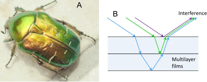
When a light shines on a material which has a fine structure with the same and/or the smaller size than the wavelength of a light, a part of the light is diffracted. This coloring phenomenon based on the spectroscopy is called as a structural color [1]. This phenomenon can be seen nearby [2]. Compact disk, soap bubble and beetles themselves don’t have a color, while they show a color by the interference of a light through their fine structures. The color of soap bubbles and oil films is originated from the thin film interference (Fig.1.1). At the thin film with thickness similar to the optical light, the light with the wavelength corresponding to the thickness of the film is seen as a colored light, since the reflected lights at the upper surface and the lower surface of the film interfere. Multi-layered thin films realize variety of colors by the combination of different thickness and the number of thin films. The color rich in metallic luster seen on jewel beetles is coming from the multi-layered thin film structure (Fig.1.2). The unevenness on the aluminum of the CD/DVD optical storage media also interfere optical lights like a diffraction grating. This leads to the iridescent color of the recoding side of CD/DVD.
Morpho butterfly wings are called living jewels and show brilliant blue color (Fig.1.3).
This blue color is a structural color due to the lattice-like structure engraved on the scale surface. Jewelry opals show a variety of colors by the optical interference through the silicate fine particles regularly arranged (Fig.1.4).
Film of a soap bubble
A B
Figure 1.1 Colors appear on a soap bubble (A) and a schematic of a light interference at a soap bubble film (B).
Interference
Multilayer films
A
B
Figure 1.2 The color rich in metallic luster on a jewel beetle (A) and a schematic of a multilayer interference (B).
Interference
A
B
Figure 1.3 Brilliant blue color of morpho butterfly wings (A) [3] and a schematic of a light interference at morpho butterfly wing scales (B).
Interference
A B
Figure 1.4 A variety of colors on Opal (A) [4] and a schematic of a light interference at an opal structure (B).
This structural color is characterized by the color variation depending the angle to see.
Different from color materials, since the structural color does not decolorize by ultraviolet rays and free from poisonous heavy metals, the industrial application of it for the texture and automobile coloring has been investigated.
A fine particle with a diameter about 1 to 500 nm is called as a colloidal particle.
When colloidal particles with uniform particle size arrange periodically, it is called as a colloidal crystal by the similarity of the standard crystals. In most of the cases, colloidal crystals have about the same structural periodicity as the optical wavelength of a visible light. Therefore, they diffract such wavelength selectively (Bragg’s reflection), and shine beautifully.
Materials which have periodically distributed refractive index are in general called photonic crystals [5]. Normally, that periodicity is nearly the same as the wavelength of the visible light. They diffract the optical light with nearly the same wavelength as their periodicity by the Bragg’s reflection, and exhibit the characteristic optical properties which are different from the uniform optical materials. That is why, these materials are specially called as photonic crystals to distinguish their unique optical functions and properties. A typical schematic example of photonic crystals is shown in Fig.1.5. One-dimensional (1D) photonic crystal shown in Fig.1.5-A is represented by the multi-layered thin film. This 1D periodical structure was intensively investigated and applied as the reflection structure of DFB (distributed feedback) laser. Two-dimensional (2D) photonic crystal represented by Fig.1.5-B is composed of the regularly arrangement of infinitely long structures in a grid pattern. Three-dimensional (3D) photonic crystal has the regularly arranged structure similar to a crystal structure as shown in Fig.1.5-C.
In nature, similar structures have been reported for all from 1 to 3 dimensional types.
In addition, the photonic crystal has a photonic band gap (PBG) that blocks a specific wavelength of light.
The concept of PBG is introduced by E. Yablonovitch [6] and S. John [7]. PBG can be explained in the same way as the origin of the band gap for electrons in solid crystals. In a standard solid crystal, the electron which has certain energy cannot either propagate in the crystal or even exist by the Bragg reflection at any direction because of the existence of the periodical potential created by the atomic nucleus. This is so-called band-gap.
Similar to this, the optical light which has certain wavelength cannot either propagate in the crystal or even exist by the Bragg reflection at any direction because of the existence
of the periodical refractive index distribution created in the photonic crystal. When the 3D refractive index distribution is formed as shown in Fig.1.6, the frequency range which cannot propagate in any direction appears as shown in the band diagram of Fig.1.7 (the horizontal axis is corresponding to the different optical propagation direction, the vertical axis is the frequency). This is the photonic band gap, PBG [8]. Usage of the PBG may realize the light confinement. Therefore, the application for the future quantum computer is also expected.
A B C
Figure 1.5 Schematic of photonic crystals, 1 dimensional (A), 2 dimensional (B) and 3 dimensional (C).
Figure 1.6 Example of the 3D photonic crystal [8]. Photonic band gap appears by forming the 3D refractive index distribution.
Colloidal crystals are one type of photonic crystals. Both colloidal crystals and photonic crystals have the name of ’crystal’, however, colloidal crystals are named from the view points of structural unit while photonic crystals are named focusing on the functions. Photonic crystals in general have a variety of types without the limitation to the particle arrangement. In this sense, sometimes, colloidal crystals are called colloidal photonic crystals.
Representative of natural photonic crystal is Opal. Opal’s characteristic iridescent color is called in general play-of-color. Opal is a soft rock composed of hydrous silica.
Normalized frequency (c/a)
Photonic band-gap
Figure 1.7 Band structure of the 3D photonic crystal in Fig.1.6 [8]. Horizontal axis is the propagation direction of the optical light, vertical axis is the frequency (wavelength) of the optical light.
Sanders reported that fine particles formed closed-packed crystal structure (face centered cubic structure) in Opal (Fig.1.8) [9]. Therefore, a colloidal crystal of which fine particles have close-packing are called an Opal crystal.
Figure 1.8 Micrographs of heavily etched fracture surface of a colored Opal [9].
A B
A B
Figure 1.9 Schematic of a colloidal crystal, A: close-packed crystal structure, B:
non-close-packed colloidal crystal.
Colloidal crystals are mostly categorized into a closely-packed colloidal crystal
(Fig.1.9-A) and a non-closely-packed colloidal crystal (Fig.1.9-B) [10]. In the case of Fig.1.9-A, each particle contacts each other and forms periodical arrangement (system of hard spheres). In the case of Fig.1.9-B, all particles have the same electrostatic charge, and each particle keeps the certain constant distance by the electrostatic repulsion (system of charged particles). A colloidal crystal of polystyrene (PS) particles is one of the representative in this system. When PS particles are dispersed in water, the surface of particles is negatively charged due to the dissociation of the surface dissociative groups such as sulfate groups.
The colloidal crystal film, i.e. an ordered array of colloid particles, is promising for the different types of 2D/3D-photonic materials and structural color substances, such as optical waveguides and sensors, due to its wide range of coloring derived from Bragg’s diffraction in the visible wavelength region. In the past decades, several potential applications have been reported such as photonic ink systems, photonic rubber sheet and photonic crystal lasers, bio/chemical sensors and bio-inspired materials including pH and ion concentration detection [11–23].
1.2 Techniques to fabricate the colloidal crystals
Colloidal crystal films have been synthesized by the various techniques, such as the solvent evaporation method [24, 25], the template-directed crystallization method [26], the natural sedimentation method [27], the spin coating method [28, 29], the Langmuir-Blodgett method [30], and the sealed cell method [31], floating packing [32], electric-field assisted convective assembly [33] and air-pulse-drive assembly [34]. Technical improvement toward a better film fabrication process represented by vertical deposition methods [35, 36] and the cell packing method [37] has also been continued. Fudouzi et al. reported the oil covering method to form a high quality, self-assembled closest packing flat colloidal crystal film over a large area [38].
Among thees techniques, here, there kinds of representative techniques are overviewed.
A typical method is the vertical deposition method. This method was proposed by Colvin et al. [35] and is also called the Colvin method. As shown in the schematic diagram of Fig.1.10, when a substrate such as a glass slide is vertically immersed in a suspension in which colloidal spherical particles are dispersed and allowed to stand, a meniscus is formed at the contact portion with the substrate. When the solvent evaporates from
the tip of the meniscus, convection is generated to compensate for the evaporation, and the particles are carried to the tip of the meniscus, and are regularly arranged by the capillary force acting between the particles [39]. In addition, the evaporation rate of the solvent can be controlled by the temperature of the solvent and the kind of the solvent.
Colvin et al. have succeeded in depositing single crystals of colloidal spherical particles on a wide variety of substrates, and could easily fabricate films in thicknesses from single to 100 layers by controlling the volume fraction and size of the particles [35]. Zhao et al. [40] succeeded in producing crack-free colloidal crystals by adding a silica precursor to the suspension. When no silica precursor was added, cracks were formed between the particles originated from volume shrinkage due to solvent evaporation. However, it was reported that when a silica precursor was added, the silica precursor penetrated into the gaps between the spherical silica particles, and the effect of volumetric shrinkage during solvent evaporation could be counteracted.
Self-assembly
substrate
Evaporation
Microspheres
Figure 1.10 Schematic of the vertical deposition method.
Another method is the dip coating method. This method was proposed by Sato et al.
[36]. In this method, a colloidal crystal is formed using the capillary phenomenon as in the vertical deposition method. In the vertical deposition method, the film thickness was controlled by the solvent evaporation rate. However, if the number of particles changes during the solvent evaporation, the film thickness may be affected. To solve this problem, the film thickness was controlled by lifting the substrate from the suspension at a constant speed, rather than relying on solvent evaporation, as shown in the schematic diagram of Fig.1.11. Sato et al. [36] reported that high-quality and uniform colloidal crystals could be prepared by controlling the particle concentration or the withdrawing rate.
The other method is the oil coating method. The oil coating method was proposed by Fudouzi et al. [38]. As shown in the schematic diagram of Fig.1.12, this method
Withdrawing
substrate
Figure 1.11 Schematic of the dip coating method.
utilizes the phenomenon that the suspension concentrates and crystallizes on a horizontal substrate under a silicone oil coating. The oil coating method has the advantages that the solvent evaporation rate of the suspension can be controlled, and the formation of cracks due to volume shrinkage can be prevented by infiltration of silicone oil into the voids of the particles during the solvent evaporation. Fudouzi et al. succeeded in producing colloidal crystals with a particle size of 200µm or more on a substrate of 75 cm2 without special equipment [38]. They also reported its application as a sensor that changes color in response to environmental changes using the unique optical property of the colloidal crystal of which structural color changes due to microscopic deformation [41, 42]. For example, research has been reported on smart materials [43] that can easily detect liquids, and strain visualization sheets [44] that allow visual inspection of deformation of structural materials, using the property that the structural color changes due to the swelling phenomenon.
substrate
Silicone oil
Figure 1.12 Schematic of the oil coating method.
The above method has the merit that colloidal crystals can be easily prepared without the need for special equipment, since colloidal crystals are formed by self-assembly of the colloidal particles. However, these methods need a very long time for the film fabrication.
Therefore, to realize the industrial low cost and mass production, a faster film fabrication
technique has been desired.
1.3 The electrophoretic deposition method
Recently, electrophoretic deposition (EPD) is becoming one of the promising candidates to realize the rapid colloidal crystal film fabrication.
The EPD process itself is a widely used coating process for many industrial applications. This process is characterized by the migration of colloidal particles in a liquid under an electric field, i.e., electrophoresis, and the subsequent deposition onto an electrode. The rubber coating by means of electrodeposition has been known since 1925 based on the fact that the colloid particles in latex are generally negatively charged [45]. This negatively charged nature leads to the subsequent research of the EPD of polystyrene (PS) spheres to form colloidal crystals, together with the inquiry of forming photonic crystals.
As an alternative method to fabricate the colloidal crystal films, the electrophoretic deposition (EPD) method [46] was focused in this work. The EPD method is positioned as one of the colloid processes. Solidification molding is performed by applying an electric field to the suspension of the raw material powder and causing the particles to electrophoresis in the direction of the positive or negative electrode whose surface charge differs from that of the electrode. Although the mechanism of particle deposition in the EPD process is not completely elucidated, in general, particles migrate under the application of an electric field, and when they reach the substrate surface, the repulsive potential between the particles decreases, resulting the agglomeration of the particles by van der Waals attraction. Figure 1.13 shows the migration and deposition of particles and ions in the suspension to which an electric field is applied. Particles following the electric double layer migrate in the solvent, and when they reach the substrate, they gradually lose their electric double layer and aggregate and deposit.
Whereas other colloidal crystal deposition methods are uniaxial growth, the EPD method is expected to significantly reduce the deposition time because particles are deposited in the perpendicular direction to the substrate. In addition, it is expected that the cost can be reduced because the base material can be easily scaled up and uniform coating can be performed on a large area in a short time [45, 47–53].
In 1999, Lopez et al. [49] produced colloidal crystals made of SiO2 particles with
Figure 1.13 Schematic of electrophoresis and deposition of the particles and ions in the suspension [46].
a particle size in the range of 300 to 550 nm by the EPD method using a horizontal substrate, demonstrating the importance of applying the concept of EPD to colloidal sedimentation. In 2000, under the conditions of a deposition time of 30 min and an applied electric field strength of 4 V/cm, Rogach et al. produced a colloidal crystal made of PS nanoparticles with 200 - 300 nm diameters on a 3 × 0.5 cm2 indium tin oxide (ITO) coated glass (ITO/glass) electrode with higher crystallinity than other methods, and dramatically improved the production time [47]. Since then, the research of colloidal crystal films was directed to faster fabrication, size enlargement, and quality control.
In 2006, Gonzalez et al. [50] mentioned the importance to consider the detailed arrangement of apparatus in EPD methods. They have succeeded in fabricating colloidal crystals with larger domain size and fewer defects by EPD method, considering the liquid flow from the view points of fluid dynamics, e.g. proposed by Von Karman et al. [54].
In 2008, Pu-Wei Wu [48] et al. arranged a substrate vertically, and under the conditions of deposition time 120 min, applied electric field strength of 20 V/cm, and pH 10, a colloidal crystal with an average domain size of 400µm2 was successfully obtained. The results show that the colloidal crystals were much larger than the particle area (<90 µm2 [47, 55–64]) of the colloidal crystals obtained by other methods, so that highly crystalline colloidal crystals could be produced.
One of the investigations for size enlargement can be seen using SiO2 (which has a narrower processing window than PS) colloidal crystals in 2008 by Huang et al. [48]. They demonstrated SiO2 colloidal crystal film formation on a 1 × 1 cm2 n-type Si wafer for
120 minutes. Recently, Katagiri et al. reported a SiO2 colloidal crystal film on 1×4 cm2 ITO/glass for 25 minutes [65]. These reports demonstrated a faster film fabrication rate than the conventional techniques that takes days [35, 36], however, the fabrication rate of the EPD technique has still remained in the range between 30 minutes and 2 hours.
Either ethanol (EtOH) or a mixture of water and EtOH was chosen as the solvent for the EPD suspension [47, 48, 65]. This was effective to reduce the bubble formation caused by the electrolysis of water, and to realize a closest packing structure. However, the detailed effect of EtOH as well as that of other alcohols is still not yet clear regarding the EPD colloidal crystal film formation process.
In addition, the preparation of colloidal crystal films by the EPD process has been advanced, and the most recent topic is the production of amorphous colloid array by the EPD process [65, 66]. It has been pointed out that the feature of this aggregate is that it can replace ink and pigment with colloidal particles because it shows angle-independent structural color.
1.4 Interaction energy between two particles
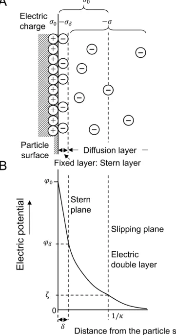
At the surface of the particle in a liquid medium, the electric double layer is formed by the electric charge of the particle surface and opposite electric charge of the counter ions which exist around the particle surface in the suspension. The electric charge of the colloidal particle surface can be formed by the following two cases. One is the adsorption of either positive ions or negative ions at the particle surface. The other is the ionization of the constituent substances of the colloid particle itself. The electric double layer is considered to be composed of the fixed layer and the diffusion layer as shown in Fig.1.14.
When the surface electric charge density of the particle, i.e. the electric charge per unit area, is σ0, the opposite electric charge density of the counter ions is −σ0. The part of
−σ0, i.e. −σδ, exists in the fixed layer called Stern layer, and the rest of −σ exists in the diffusion layer which forms ionic atmosphere at outside. This is called Gouy-Chapman diffusion double layer. Counter ions distribute in a wide area and do not exist at the constant distance from the particle surface. The average distance where counter ions exist from the particle surface is expressed by 1/κ, and this is called the thickness of the electric double layer. This κ is a parameter of the Debye-Huckel equation [67], and can be expressed in Eq.1.1. Conventionally, slipping plane which separates mobile fluid from
fluid that remains attached to the surface, is introduced. This is corresponding to the thickness of the electric double layer. ζ potential is considered to be the electric potential at the slipping plane.
κ=
√ 8πF2
1000ϵRT ×√
J (1.1)
whereF,ϵ,R and T are faraday constant, dielectric constant of the solvent, gas constant and absolute temperature, respectively. J is an ionic strength and is expressed as follows with the electrolyte concentration in the solvent, C, and the valence of the ions,Z;
J =∑
Z2C (1.2)
Therefore, by the enlargement of the ionic strength adding the electrolytes in the colloidal solution, the thickness of the electric double layer 1/κdecreases. Further, by the increase of the counter ion valence, the shrinking effect of the electric double layer becomes remarkable.
The concentration of the electrolytes in the suspension becomes important if the aggregation of particles on the electrode substrates accords the DLVO (Derjaguin-Landau-Verwey-Overbeek) theory [68]. DLVO theory is formulated by the former Soviet Union group of Derjaguin-Landau et al. and the Netherlands group of Verwey-Overbeek et al. When the stability of the colloid dispersion system is discussed, DLVO theory is frequently used. Major acting forces which affect the particle dispersion and aggregation phenomena in a liquid medium are electrostatic repulsion (VR), van der Waals attractive force (VA), gravity (VG), and buoyancy (VB). VG and VB are not considered by DLVO theory though they are also major forces acting on the particles.
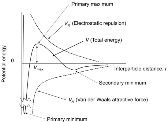
Especially in the case of particles dispersed in the suspension, the dominant forces to control the particle dispersion and aggregation areVR andVA, and the interaction energy between particles are expressed as follows;
V =VR+VA (1.3)
Figure 1.15 shows the relation between interaction energy and particle distance, r. The repulsive energyVRdecrease withrexponentially in the relation (e−κr), while the absolute value of the attractive energy VA decreases in inverse proportion to the square of the
+
+
+
+
+
+
+
+
+
+
−
−
−
−
−
−
−
−
−
−
−
−
𝜎 𝜎 𝜎
𝜎
𝜑
𝜑
0 𝛿
1/𝜅
A
B
Electric charge
Diffusion layer Particle
surface
Fixed layer: Stern layer
Electric potential
Distance from the particle surface ζ
Slipping plane Stern
plane
Electric double layer
Figure 1.14 Structure of the electric double layer (A) and the electric potential curve (B).
distancer(r12) (whenr becomes long, it decreases inversely proportional tor6). The total energy combined by these two energies, shows the general behavior of two particles when they come close each other. When the distance is relatively long, weak attractive energy is dominant. When the distance gets shorter, the repulsive force becomes dominant. When particles get closer further over the maximum point (Vmax), the attractive energy becomes dominant. Therefore, particles need to get over the maximum point of the interaction energy so that particles get closer and aggregate. If this maximum point of the interaction energy is bigger than the thermal kinetic energy of particles, particles cannot get closer over the maximum point. Even if particles get closer, they rebound from the shortest distance, and cannot aggregate. In this condition, a colloidal suspension is stable without particle aggregation.
0
Potential energy
V(Total energy)
(Van der Waals attractive force) (Electrostatic repulsion)
Primary minimum
Secondary minimum Primary maximum
Interparticle distance, r VR
VA Vmax
Figure 1.15 Interaction energy potential curve between particles in the suspension.
For the case of the certain colloidal particles, the height of the maximum point of the interaction energy is mostly defined by the potential curve of the electrostatic repulsion.
The electrostatic repulsion becomes large when the ζ potential of the particle and/or the thickness of the electric double layer 1/κ becomes large, and therefore are affected strongly by the concentration of the electrolytes and the valence of the ions. This means that the change of the electrolyte concentration bring the change of the total potential energy curve shape. Figure 1.16 shows the effect of the electrolyte concentration on
the interparticle interaction energy. The curve (a) of Fig.1.16 is the case of the low electrolyte concentration. In this case, the height of the maximum point is enough high, and the colloidal suspension is stable without aggregation. However, by increasing the electrolyte concentration, the curve (a) moves to the curve (b) and (c). By the increase of the electrolyte concentration, a part of the particle surface charge is neutralized, and the thickness of the electric double layer becomes thinner. Consequently, the electric repulsion force decreases, and particles begin to aggregate. As shown in Fig.1.16-(b), the height of the maximum point becomes quit low, and particles get close easier because particles can get over the maximum point easier. Under the very high electrolyte concentration of Fig.1.16-(c), the maximum point disappears, resulting the inevitable aggregation of the particles.
Interparticle distance, r (a) Low electrolyte concentration
(c) High electrolyte concentration (b) Medium electrolyte concentration
Potential energy
0
Figure 1.16 Effect of the electrolyte concentration on the interparticle interaction energy.
These explanation indicate that the low electrolyte concentration in the colloidal suspension makes the electric double layer thicker, and increase the dispersibility of particles in the suspension, which correspond to the stability of the suspension. This condition could be advantageous for the EPD growth of the colloidal crystal films.
1.5 Purpose of this study and thesis overview
To date, there have been many examples of colloidal crystals produced by the EPD method, but the film area is relatively small (<4.0 cm2 [27-33, 46, 47]) and no roll-shaped substrate has been used. In order to commercialize colloidal crystal films, it is necessary to break away from batch processing and mass-produce, so it is promising to combine roll-to-roll film formation technology with large-area substrates. Therefore, in this study, ITO-coated polyethylene terephthalate (PET) sheets (5×7.5, 10×15 cm2) as a large-area roll-shaped substrate was used, and only polystyrene particles with aqueous or the mixture of H2O and alcohol suspensions were used. The conditions for producing a colloidal crystal film at high speed from aqueous suspension mixed with ethanol (EtOH) by the EPD method were investigated. In addition, the subsequent crystallization process during solvent evaporation was discussed because the film immediately after EPD showed interesting behavior during drying in the experiment. Furthermore, silicone elastomer was filled in the gaps between the three-dimensionally accumulated colloidal particles, and a film in which polystyrene particles were fixed was fabricated. The possibility of applying the colloidal crystal film produced by the EPD method to a sensor for detecting volatile liquid and a sheet for visualizing strain was also examined.
This thesis is organized in six chapters as follows:
Chapter 2 Detailed investigation of the optimal condition for the EPD colloidal crystal film formation. The effect of the aqueous PS colloidal suspension and the mixture with alcohol on the colloidal crystal film growth is discussed.
Chapter 3 Investigation and discussion on the growth mechanism of the colloidal crystal films from the concentrated aqueous ethanol suspension.
Chapter 4 The effect of the poly-dimethylsiloxane (PDMS) elastomer filling to the interparticle space of the colloidal crystal film to realize the soft photonic crystals. The potential use of the colloidal crystal films with PDMS filling for the strain detection sensors is demonstrated.
Chapter 5 Characterization of swelling phenomena by immersing different kinds of silicone oil and other organic compounds as solvents. The possibility of the obtained
colloidal crystal film with PDMS elastomer filling as volatile liquid sensor is demonstrated.
Chapter 6 The general conclusions of my research and future prospects are given.
References
[1] J. Sun, B. Bhushan, and J. Tong. Structural coloration in nature. RSC Adv., 3:14862–14889, 2013.
[2] S. Kinoshita. Structural colors in the realm of nature. World Scientific, 2008.
[3] E. Armstrong and C. O’Dwyer. Artificial opal photonic crystals and inverse opal structures - fundamentals and applications from optics to energy storage. J. Mater.
Chem. C, 3:6109–6143, 2015.
[4] B. Rondeau, E. Fritsch, F. Mazzero, J. P. Gauthier, B. Cenki-Tok, E. Bekele, and E. Gaillou. Play-of-color opal from wegel tena, wollo province, ethiopia. GEMS and GEMOLOGY, 46:90–105, 2010.
[5] ´A. Blanco and C. L´opez. Photonic crystals: fundamentals and applications. Annual Review of Nano Research, 1:81–152, 2006.
[6] E. Yablonovitch. Inhibited spontaneous emission in solid-state physics and electronics. Phys. Rev. Lett., 58:2059–2062, 1987.
[7] S. John. Strong localization of photons in certain disordered dielectric superlattices.
Phys. Rev. Lett., 58:2486–2489, 1987.
[8] S. Noda. Photonic crystals. Jpn. J. Optics, 30:56–64, 2001.
[9] J. V. Sanders. Colour of precious opal. Nature, 204:1151–1153, 1964.
[10] F. Meseguer and R. Fenollosa. Non-close packed colloidal crystals. J. Mat. Chem., 15:4577–4580, 2005.
[11] A. C. Arsenault, H. Miguez, V. Kitaev, G. A. Ozin, and I. Manners. A polychromic, fast response metallopolymer gel photonic crystal with solvent and redox tunability:
A step towards photonic ink (P-Ink). Adv. Mater., 15:503–507, 2003.
[12] H. Fudouzi and Y. N. Xia. Photonic papers and inks: Color writing with colorless materials. Adv. Mater., 15:892–896, 2003.
[13] J. Zhang, Y. Li, X. Zhang, and B. Yang. Colloidal self-assembly meets nanofabrication: from two-dimensional colloidal crystals to nanostructure arrays.
Adv. Mater., 22:4249–4269, 2010.
[14] T. Zhang, Y. Ma, and L. Qi. Bioinspired colloidal materials with special optical, mechanical, and cell-mimetic functions. J. Mater. Chem. B, 1:251–264, 2013.
[15] H. Cong, B. Yu, J. Tang, Z. Li, and X. Liu. Current status and future developments in preparation and application of colloidal crystals. Chem. Soc. Rev., 42:7774–7800, 2013.
[16] A. Stein, B. E. Wilson, and S. G. Rudisill. Design and functionality of colloidal-crystal-templated materials-chemical applications of inverse opals. Chem.
Soc. Rev., 42:2763–2803, 2013.
[17] N. Vogel, M. Retsch, C. A. Fustin, A. D. Campo, and U. Jonas. Advances in colloidal assembly: the design of structure and hierarchy in two and three dimensions. Chem.
Rev., 115:6265–6311, 2015.
[18] C. F. Lai and Y. C. Wang. Colloidal photonic crystals containing silver nanoparticles with tunable structural colors. Crystals, 6:61–1–10, 2016.
[19] K. Lee and S. A. Asher. Photonic crystal chemical sensors: pH and ionic strength.
J. Am. Chem. Soc, 122:9534–9537, 2000.
[20] Y. J. Lee and P. V. Braun. Tunable inverse opal hydrogel pH sensors. Adv. Mat., 15:563–566, 2003.
[21] O. L. J. Pursiainen, J. J. Baumberg, K. Ryan, J. Bauer, H. Winkler, B. Viel, and T. Ruhl. Compact strain-sensitive flexible photonic crystals for sensors. Appl. Phys.
Lett., 87:101902, 2005.
[22] Y. Iwayama, J. Yamanaka, Y. Takiguchi, M. Takasaka, K. Ito, T. Shinohara, T. Sawada, and M. Yonese. Optically tunable gelled photonic crystal covering almost the entire visible light wavelength region. Langmuir, 19:977–980, 2003.
[23] H. Fudouzi and T. Sawada. Photonic rubber sheets with tunable color by elastic deformation. Langmuir, 22:1365–1368, 2006.
[24] A. S. Dimitrov and K. Nagayama. Continuous convective assembling of fine particles into two-dimensional arrays on solid surfaces. Langmuir, 12:1303–1311, 1996.
[25] S. Rakers, L. Chi, and H. Fuchs. Influence of the evaporation rate on the packing order of polydisperse latex monofilms. Langmuir, 13:7121–7124, 1997.
[26] A. van Blaaderen, R. Ruel, and P. Wiltzius. Template-directed colloidal crystallization. Nature, 385:321–324, 1997.
[27] R. Mayoral, J. Requena, J. S. Moya, C. L´opez, A. Cintas, H. Miguez, F. Meseguer, L. V´azquez, M. Holgado, and A. Blanco. 3D long-range ordering in ein SiO2
submicrometer-sphere sintered superstructure. Adv. Mater., 9:257–260, 1997.
[28] P. Jiang and M. J. McFarland. Large-scale fabrication of wafer-size colloidal crystals, macroporous polymers and nanocomposites by spin-coating. J. Am. Chem. Soc., 126:13778–13786, 2004.
[29] A. Mihi, M. Ocana, and H. Miguez. Oriented colloidal-crystal thin films by spin-coating microspheres dispersed in volatile media. Adv. Mater., 18:2244–2249, 2006.
[30] S. Reculusa and S. Ravaine. Synthesis of colloidal crystals of controllable thickness through the Langmuir-Blodgett technique. Chem. Mater., 15:598–605, 2003.
[31] S. H. Park, B. Gates, and Y. Xia. A three-dimensional photonic crystal operating in the visible region. Adv. Mater., 11:462–466, 1999.
[32] Y. Fu, Z. Jin, G. Liu, and Y. Yin. Self-assembly of polystyrene sphere colloidal crystals by in situ solvent evaporation method. Synth. Met., 159:1744–1750, 2009.
[33] J. Kleinert, S. Kim, and O. D. Velev. Electric-field-assisted convective assembly of colloidal crystal coatings. Langmuir, 26:10380–10385, 2010.
[34] T. Kanai, T. Sawada, A. Toyotama, and K. Kitamura. Air-pulse-drive fabrication of photonic crystal films of colloids with high spectral quality. Adv. Funct. Mater., 15:25–29, 2005.
[35] P. Jiang, J. F. Bertone, K. S. Hwang, and V. L. Colvin. Single-crystal colloidal multilayers of controlled thickness. Chem. Mater., 11:2132–2140, 1999.
[36]Z. -Z.Gu,A.Fujishima,andO.Sato.Fabricationofhigh-qualityopalfilmswith controllable thickness. Chem. Mater., 14:760–765, 2002.
[37] B. Gates and Y. Xia. Fabrication and characterization of chirped 3D photonic crystals. Adv. Mater., 12:1329–1332, 2000.
[38] H. Fudouzi. Fabricating high-quality opal films with uniform structure over a large area. J. Coll. Interf. Sci., 275:277–283, 2004.
[39] K. Shimizu, S. Watanabe, and M. T. Miyahara. Controlling self-assembled periodic structures of colloidal particles by convective self-assembly. J. Soc. Powder Technol., Japan, 54:23–26, 2017.
[40] L. Wang and X. S. Zhao. Fabrication of crack-free colloidal crystals using a modified vertical deposition method. J. Phys. Chem. C, 111:8538–8542, 2007.
[41] H. Fudouzi. Optical properties caused by periodical array structure with colloidal particles and their applications. J. Soc. Powder Technol., Japan, 43:287–294, 2006.
[42] H. Fudouzi. Colloidal photonic crystal films: Fabrication and tunable structural color and applications. Nanomaterials and Nanoarchitectures, Springer, Chapter 1:1–19, 2015.
[43] H. Fudouzi and T. Sawada. Photonic crystal sensing of components of a liquid mixture using an optical fiber spectrometer. Prod. of SPIE, 6767:676704, 2007.
[44] H. Fudouzi, T. Sawada, Y. Tanaka, I. Ario, T. Hyakutake, and I. Nishizaki. Smart photonic coating as a new visualization technique of strain deformation of metal plates. Proc. SPIE, 8345:83451S, 2012.
[45] S. E. Sheppard and L. W. Eberlin. The electrodeposition of rubber. Ind. Eng. Chem., 17:711–714, 1925.
[46] T. Uchikoshi. Microstructure design of ceramics by controlling the dispersion of fine particles in a liquid, and the application of the design technique to fabricate novel materials. The Micromeritics, 57:36–42, 2014.
[47] A. L. Rogach, N. A. Kotov, D. S. Koktysh, J. W. Ostrander, and G. A. Rgaisha.
Electrophoretic deposition of latex-based 3D colloidal photonic crystals: A technique for rapid production of high-quality opals. Chem. Mater., 12:2721–2726, 2000.
[48] Y. J. Huang, C. H. Lai, and P. W. Wu. Fabrication of large-area colloidal crystals by electrophoretic deposition in vertical arrangement. Electrochem. Solid State Lett., 11:P20–P22, 2008.
[49] M. Holgado, F. Garc´ıa-Santamar´ıa, A. Blanco, M. Ibisate, A. Cintas, H. M´ıguez, C. J. Serna, C. Molpeceres, J. Requena, A. Mifsud, F. Meseguer, and C. L´opez.
Electrophoretic deposition to control artificial opal growth. Langmuir, 15:4701–4704, 1999.
[50] M. Yoldi, W. Gonz´alez-Vi nAs, M. C. Arcos, and R. Sirera. Electrophoretic deposition of colloidal crystals assisted by hydrodynamic flows. J. Mater. Sci., 41:2965–2969, 2006.
[51] J. Hamagami. Fabrication of particle assembly by using electropboretic deposition process. J. Soc. Powder Technol., Japan, 45:229–235, 2008.
[52] C. H. Lai, Y. J. Huang, P. W. Wu, and L. Y. Chen. Rapid fabrication of cylindrical colloidal crystals and their inverse opals. J. Electrochem. Soc., 157:P23–P27, 2010.
[53] D. Mokude, A. Takasu, and M. Higuchi. Electrophoretic non-ionic nano-spheres (latexes) for structural coloring. Polymer, 117:243–248, 2017.
[54] P. J. Zandbergen and D. Dijkstra. Von karman swirling flows. Annu. Rev. Fluid
Mech., 19:465–491, 1987.
[55] L. Liu, P. Dong, R. Liu, Q. Zhou, X. Wang, G. Yi, and B. Cheng. Preparation and self-assembly of uniform TiO2/SiO2 composite submicrospheres. J. Colloid Interface Sci., 288:1–5, 2005.
[56] Y. Masuda, T. Itoh, M. Itoh, and K. Koumoto. Self-assembly patterning of colloidal crystals constructed from opal structure or NaCl structure. Langmuir, 20:5588–5592, 2004.
[57] Y. H. Ye, F. LeBlanc, A. Hach´e, and V. V. Truong. Self-assembling three-dimensional colloidal photonic crystal structurewith high crystalline quality. Appl. Phys. Lett., 78:52–54, 2001.
[58] C. A. Fustin, G. Glasser, N. W. Spiess, and U. Jonas. Parameters influencing the templated growth of colloidal crystals on chemically patterned surfaces. Langmuir, 20:9114–9123, 2004.
[59] P. Ferrand, M. J. Minty, E. Egen, J. Ahopelto, R. Zentel, S. G. Romanov, and C. M. S. Torres. Micromoulding of three-dimensional photonic crystals on silicon substrates. Nanotechnology, 14:323–326, 2003.
[60] C. H. Chan, C. C. Chen, C. K. Huang, W. H. Weng, H. S. Wei, H. Chen, H. T. Lin, H. S. Chang, W. Y. Chen, and W. H. Chang. Self-assembled free-standing colloidal crystals. Nanotechnology, 16:1440–1444, 2005.
[61] R. C. Hayward, D. A. Saville, and I. A. Aksay. Electrophoretic assembly of colloidal crystals with optically tunable micropatterns. Nature, 404:56–59, 2000.
[62] E. Kumacheva, R. K. Golding, M. Allard, and E. H. Sargent. Colloid crystal growth on mesoscopically patterned surfaces: Effect of confinement. Adv. Mater., 14:221–224, 2002.
[63] M. H. Kim, H. K. Choi, S. H. Im, and O. O. Park. Fabrication of robust, high-quality two-dimensional colloidal crystals from aqueous suspensions containing water-soluble polymer. Appl. Phys. Lett., 88:143127, 2006.
[64] S. Badilescu, A. R. Hajiaboli, N. Seirafianpour, R. B. Sadeghian, M. Kahrizi, and V. V. Truong. Study of the structural evolution within polystyrene and polystyrene-gold composite colloidal crystals by atomic force microscopy and scanning electron microscopy. Appl. Phys. Lett., 90:023113, 2007.
[65] K. Katagiri, Y. Tanaka, K. Uemura, K. Inumaru, T. Seki, and Y. Takeoka. Structural color coating films composed of an amorphous array of colloidal particles via
electrophoretic deposition. NPG Asia Mater., 9:e355, 2017.
[66] K. Katagiri, K. Uemura, R. Uesugi, K. Inumaru, T. Seki, and Y. Takeoka.
Structurally colored coating films with tunable iridescence fabricated via cathodic electrophoretic deposition of silica particles. RSC Adv., 8:10776–10784, 2018.
[67] P. Debye and E. Huckel. The theory of electrolytes. I. Lowering of freezing point and related phenomena. Physikalische Zeitschrift, 24:185–206, 1923.
[68] M. Elimelech, J. Gregory, and X. Jia. Particle deposition and aggregation, 1st edition, measurement, modelling and simulation. Elsevier, 1995.
Chapter
2
Fast fabrication of PS colloidal crystal films
by the electrophoretic deposition
2.1 Introduction
In this work, the EPD technique was chosen to fabricate the colloidal crystal films faster than the other techniques. Nevertheless, the fabrication rate of the previously reported EPD technique has still remained in the range between 30 minutes and 2 hours. Either ethanol (EtOH) or a mixture of water and EtOH was chosen as the solvent for the EPD suspension [1–3]. This was effective to reduce the bubble formation caused by the electrolysis of water, and to realize a closest packing structure. However, the detailed effect of EtOH as well as that of other alcohols is still not yet clear regarding the EPD colloidal crystal film formation process.
In this study, removal of ionic contaminants, applications of a pulsed current and the effect of the water+alcohol mixture solvent on the formation of colloidal crystal film by the EPD process were investigated. Subsequently, the detail effect of the EtOH solvent was investigated taking into account the withdrawing rate of the substrate. Proper EPD conditions satisfying both the film quality and fast processing rate less than 10 minutes order were discussed. Based on these conditions, the large area EPD colloidal film formation was also demonstrated.
2.2 Experimental procedure
Figure 2.1A shows the photograph of the EPD apparatus. Either an ITO/glass or an ITO coated PET (polyethylene terephthalate) sheet (ITO/PET) was used as the substrate/anode. In contrast, a stainless-steel plate was used as the counter electrode/cathode. The distance from the ITO/glass or ITO/PET to the stainless-steel plate was 1.0 and 2.5 cm, respectively. After immersing the electrodes in the colloidal suspension, a DC voltage ranging from 3 to 20 V/cm was applied for 5 minutes (Fig.2.1B).
Figure 2.1D shows the concept image of the electrophoresis, where PS colloid particles migrate to the anode electrode since the PS colloid is negatively charged in the suspension.
After the EPD process, the substrate was removed from the suspension at different withdrawing rates from 0.1 to 10 mm/sec. The substrate was then dried horizontally at room temperature. The thickness of the films was several to several tens of microns depending on the preparation conditions. The effect of the pulse voltage application during the EPD process was also investigated for comparison with the constant voltage
![Figure 1.7 Band structure of the 3D photonic crystal in Fig.1.6 [8]. Horizontal axis is the propagation direction of the optical light, vertical axis is the frequency (wavelength) of the optical light.](https://thumb-ap.123doks.com/thumbv2/123deta/5963129.2062938/14.892.208.708.79.331/structure-photonic-horizontal-propagation-direction-vertical-frequency-wavelength.webp)
![Figure 1.13 Schematic of electrophoresis and deposition of the particles and ions in the suspension [46].](https://thumb-ap.123doks.com/thumbv2/123deta/5963129.2062938/19.892.332.583.76.340/figure-schematic-electrophoresis-deposition-particles-ions-suspension.webp)