Switching Scheme in IMT-2000
Guidance
Professor Masao FUKUSHIMA
Associate Professor Tetsuya TAKINE
Shiro TSUCHIYAMA
2000 Graduate Course
in
Department of Applied Mathematics and Physics
Graduate Scho ol of Informatics, Kyoto University
KYOTO UNIVERS ITY
FO
UKYOTON DED 1JAPAN897
February 2002
Thenumb erofusers ofmobilecommunicationssystemshas increaseddramatically. Inparticu-
lar, mobile phones havethoroughly p enetrated people's dailylives. And then, various services
including video, voice, fax and data transmission are demanded. To meet these demands,
the implementation of an advanced mobile communications system is required. International
Telecommunication Union (ITU) is now formulating standards for International Mobile T-
elecommunication2000 (IMT-2000)that isthe nextgenerationmobilecommunication system.
Itmakesthefollowingservicespossible: hightransmissionsp eed,hightransmissionqualityand
the realization of global services accessible anywhere inthe world.
The dynamic channelswitching scheme inRadio Network Controller(RNC) is prop osed for
IMT 2000. It has two typ es of channels, i.e., dedicated channels and a common channel, for
datatransmission. Thededicatedchannelis allo catedtoone UserEquipment(UE)exclusively
and provides high-quality data transmission without either delay or data loss. On the other
hand, the common channel isshared by many UEs. These channelsare dynamically allo cated
toUEsbasedonthecontrolparameterssetinRadioResourcesController(RRC).Thedynamic
channelallocationrealizes economical and ecient use of these channels.
In this thesis, we propose an approximate model of the dynamic channelswitching system.
We describe the model by a continuous-time nite-state Markov chain, and then we apply
the ecient procedurecalled Replacement Process Approach tosolve the stationaryequations
of the Markov chain. Through numerical experiments, we examine quantitative p erformance
of the system, i.e., the frame dropping probability, the load of a dedicated channel and the
frequency of channel reallocation. Using those results, we can choose the control parameters
to realizethe demanded performance of the system.
1 Intro duction 1
2 Wideband CDMA 2
2.1 UMTSarchitecture : : : : : : : : : : : : : : : : : : : : : : : : : : : : : : : : : : 2
2.2 Radio interfaceprotocol architecture : : : : : : : : : : : : : : : : : : : : : : : : 2
2.2.1 Overallprotocol structure : : : : : : : : : : : : : : : : : : : : : : : : : : 2
2.2.2 RLC/MAClayer : : : : : : : : : : : : : : : : : : : : : : : : : : : : : : : 3
3 Dynamic channel switching scheme 5
4 Model description 6
4.1 Dynamicchannelswitching model : : : : : : : : : : : : : : : : : : : : : : : : : : 6
4.1.1 Model intro duction : : : : : : : : : : : : : : : : : : : : : : : : : : : : : : 6
4.1.2 Assumptions onarrivals and services : : : : : : : : : : : : : : : : : : : : 7
4.2 Approximate mo del : : : : : : : : : : : : : : : : : : : : : : : : : : : : : : : : : : 8
4.2.1 Model description : : : : : : : : : : : : : : : : : : : : : : : : : : : : : : : 8
4.2.2 Mathematical description : : : : : : : : : : : : : : : : : : : : : : : : : : 9
5 Analysis 10
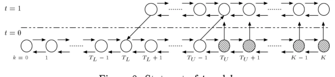
5.1 State set : : : : : : : : : : : : : : : : : : : : : : : : : : : : : : : : : : : : : : : : 10
5.2 State transitions: : : : : : : : : : : : : : : : : : : : : : : : : : : : : : : : : : : : 10
5.3 Stationary equations : : : : : : : : : : : : : : : : : : : : : : : : : : : : : : : : : 16
6 Numerical algorithm 19
7 Numerical results 24
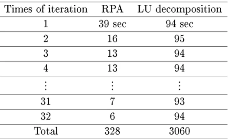
7.1 Eciencyof the proposed numerical procedure : : : : : : : : : : : : : : : : : : : 24
7.2 Accuracy of approximate mo del : : : : : : : : : : : : : : : : : : : : : : : : : : : 25
7.3 Impact of upp er threshold : : : : : : : : : : : : : : : : : : : : : : : : : : : : : : 27
8 Conclusion 29
Thenumb erofusers ofmobilecommunicationssystemshas increaseddramatically. Inparticu-
lar, mobile phones havethoroughly p enetrated people's dailylives. And then, various services
including video, voice, fax and data transmission are demanded. Tomeet these demands, the
implementationof an advancedmobile communicationssystem is required.
InternationalTelecommunicationUnion(ITU)isnowformulatingstandardsforInternational
MobileTelecommunication2000(IMT-2000)thatisthenextgenerationmobilecommunication
system. It makes the following services p ossible: high transmission speed, high transmission
quality and the realization of global services accessible anywherein the world.
The dynamic channelswitching scheme inRadio Network Controller(RNC) is prop osed for
IMT 2000. It has two typesof channelsfor data transmission: some dedicated channels and a
common channel. The dedicated channelis allo catedtoone UserEquipment(UE) exclusively
and provides high quality data transmission without either delay or data loss. On the other
hand, the common channel is shared by some UEs. Furthermore, dynamic allocation of these
channels is performed based on the queue length, and it helps use radio resources eciently.
Thus,properallocation of channelsshouldbedone as inthe followingway.
The common channel shouldbe shared by as many UEs as p ossible. It helps accommo date
many UEs in the limited radio resources and keep many dedicated channels available. To
keep dedicated channels unused enables us to allocate them on demand. Furthermore, it has
an economical advantage, reducing the extra costs of using them. Thus, dedicated channels
should be allocated in the limited case in which UEs require high-sp eed data transmission
beyond the capacity of the common channel shared by many UEs. Of course, trac volume
being changed, they shouldbereallocateddynamically atan appropriatetime.
These controls (allocation and reallocation) are performed based on a decision of Radio
Resources Controller (RRC) in RNC.Note that the p erformance of these controls depends on
the control parameters set by RRC. Therefore, weshould determine these parameters in such
a way that the most ecientand economical use of radio resources and higherquality of data
transmission are provided. Thus, wepresent the performance analysis of the dynamic channel
switching scheme toobtain the appropriate control parametersin this thesis.
The rest of this thesis is organized as follows. Section 2 summarizes the radio interface
protocolarchitecturespeciedinIMT-2000. Section3describesthe dynamicchannelswitching
schemementionedabove,andinSection4,the mathematicalmodel oftheschemeispresented.
Section5providesanumericalsolutionmethodtowhichiterativealgorithmcalledReplacement
ProcessApproach(RPA)isapplied. Section6describesalgorithmstepstoexecutetheprop osed
method, and numerical results are presented in section 7. Finally, the thesis is concluded in
Section 8.
2.1 UMTS architecture
To provideend users with the necessary service quality for multimedia communications, ex-
ible and high-bit-rate capabilities are required. Universal Mobile telecommunications System
(UMTS) is anew radio accessnetworkbased on5 MHzW-CDMA, and optimized for ecient
support of the next generation multimediaservices.
Figure 1 shows the general system architecture of UMTS outlined in [2]. It includes UEs,
UniversalTelecommunicationRadioAccess Network(UTRAN)and acorenetwork. Thefunc-
tional layering of the UMTS system into access and non-access stratum implies a functional
division b etween UTRAN and the core network;UTRAN handles allradio-specic pro cedure,
whereas the core network handlesthe service-sp ecic procedures.
Furthermore, the general architecture includes two general interfaces: The Iu interface b e-
tween UTRAN and the core network, and the radio interface (Uu) b etween UTRAN and the
UE. In Section2.2, wewill focus onthe radio interface in UMTS.
UE UTRAN Core Network
Iu Stratum Uu
Stratum
Relay
Access Stratum (AS) Non-Access Stratum (NAS) end AS
entity
end AS entity
RRC L2/L1 RRC
L2/L1
Figure 1: UMTS architecture.
2.2 Radio interface protocol architecture
2.2.1 Overall protocol structure
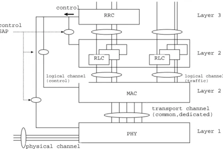
We rst present the simple structure of the radio interface protocol specied in [3], which is
layered into three protocol layers; the physical layer (Layer 1), the data link layer (Layer 2)
and the networklayer (Layer3). Figure 2shows itsarchitecture.
The physical layer oers information transfer services to Medium Access Control (MAC).
Theseservicesare providedattransp ortchannelswhichareeithercommon (i.e.,sharedamong
several users) or dedicated (i.e., allocated to a sp ecic user). These two typ es of channels
support multipleservices fairly,for example,real-time services suchasspeechand packetdata
services. Wewill focus on the dynamic allo cation of these channelsinSection 3.
described in the gure. MAC oers information transfer services to RLC. These services are
providedatlogicalchannelswhichareeithercontrol channel(i.e.,transfer controlinformation)
or trac channel(i.e., transfer user data). Furthermore, MAC p erforms the dynamic channel
allocations mentioned above. These functions of MACand RLC resp onsible for ecient data
transmission are detailed in Section2.2.2.
ThenetworklayercontainsRRCwhichalsoplaysasignicantroleinprovidingecientdata
transmission. It oerscontrolservices toRLC, MACandthephysicallayer. Theseservices are
provided at controlService AssessPoints(SAPs) between RRCwith the lowerlayers.
PHY MAC
RLC RLC
RRC control
logical channel (traffic) logical channel
(control)
physical channel
Layer 3
Layer 2
Layer 2
Layer 1 control
SAP
transport channel (common,dedicated)
Figure 2: Radio interfaceprotocol architecture.
2.2.2 RLC/MAC layer
Wewill focus on the RLC/MAC layers, whichare resp onsible for ecientdata transfer.
The RLC layer is responsible for establishment and release of layer 2 connections. The
functions performed by the RLC include segmentation and assembly, error correction by re-
transmission,owcontrol,duplicatedetection andin-sequencedeliveryofhigherlayerProtocol
Data Units(PDUs)[5].
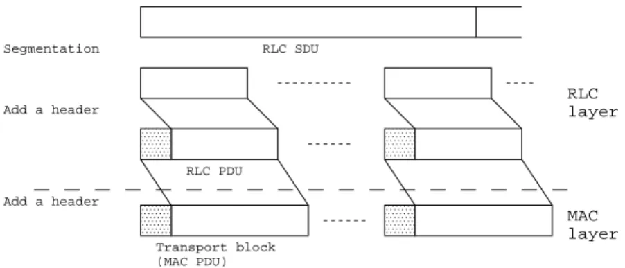
Figure3showsthesegmentationandtransformationofnetworklayerpacketdataunits. RLC
Service DataUnits (SDUs)are rst segmented intoRLC PDUs typicallycorrespondingtothe
physicallayertransp ortblo cks. EachRLCPDUcontainsasequencenumb erused forlow-level
fastAutomaticRepeat reQuest(ARQ).Therefore,RLCreceivercheckssequencenumber when
the PDUs are reassembled. If corrupted SDU is detected, retransmissions could be requested
in acknowledged data transfer mode, or it will be simply discarded in unacknowledged data
transfer mode. MACmostly provides the following service: mapping between logical channels
and transport channels, measurements of the system state, reporting the measurement results
RLC SDU
RLC PDU
Transport block (MAC PDU)
RLC layer
MAC layer
Segmentation
Add a header
Add a header
Figure3: Segmentation and transformation of network layerpacketdata units.
toRRC,Reallocationofradio resources andowcontrol. Wepresentthese functionschieyin
view ofthe dynamicchannelswitching mechanism.
Logical channels are mapp ed into transport channels at MAC. Data delivered from RLC
through logical channels is deliveredto the physical layer through the transp ortchannel. The
transport channeliscomposedofthecommon transportchanneland dedicatedtransportchan-
nels. The common transp ort channel is shared bysome UEs, so that in-bandidentication of
the UEisneededwhenparticular UEis addressed. On the otherhand,eachdedicated channel
is provided toone UE exclusively.
MAC-c/sh
MAC-d
Logical channel
dedicated chanel common channel
Channel switching
Transport channel
RLC
MAC RRC
report control
RLC
Figure 4: UTRAN side MACarchitecture.
Figure4showsUTRANsideMACarchitecturerelatedwithhigherlayers. MACisconstruct-
ed from one MAC-c/sh (Common MAC) entity and some MAC-d (Dedicated MAC) entities
provided for each UE. MAC-c/sh controls access to the common transp ort channel. MAC-d
controlsaccesstodedicatedtransportchannels. MAC-dcanalsoswitchtransp ortchanneltyp e
based on the decision taken by RRC.While the common channelis used, MAC-d passes data
received by MAC-dis delivered to the lower layer through either typ e of transport channels.
Wecan also see that MAC-c/shrelieves data (whichmostly consists of controlinformation as
paging one) from the higher layer directly and delivers them through the common transp ort
channels.
Moreover,MACmeasures the system stateof RLC and MACentities, and reports the mea-
surement result to RRC. If the value representing the system state is out of the range set by
RRC, RRC provides some control services for RLC or MAC. In this way, channel switching
mentionedaboveand ow controlcan b e p erformed. Detailsare found in[4].
3 Dynamic channel switching scheme
In this section, weintroduce the dynamic channelswitchingschemeproposed for the architec-
ture specied inthe preceding sectionand [1]. This schemeprovides control services (Channel
switching and Flow control)based on the Buer Occupancies(BOs) of transmissionbuers in
RLC and MACentities.
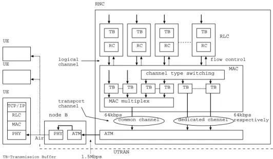
Figure5showsthesystem architecturewith dataowstodownlinks. UTRANisconstructed
from Node B (Base station) and RNC. As mentioned in the preceding section, RLC delivers
RLC PDUs to MAC through a logical channel and MAC delivers these PDUs to Layer 1
through eithertypeoftransport channels. PDUs thatbelongtoaparticular datatyp e(mainly
control information) are always delivered through the common transport channel. And others
are deliveredin the followingway.
TB
RC
channel type switching
TB TB
MAC multiplex
TB TB TB
flow control
ATM ATM
PHY node B
PHY MAC RLC TCP/IP UE
Air
RNC
common channel dedicated chennel UE
UE
TB:Transmission Buffer RC:Retransmission contorol
UTRAN
RLC
MAC logical
channel
transport channel
TB
1.5Mbps
64kbps 64kbps
respectively TB
RC
TB
RC
TB
RC
Figure5: System architecture.
MAC receives these PDUs from RLC together with information which tells BOs of RLC
transmission buer. The value of BOs is rep orted to RRC, and RRC decides which typ e of
channelb eing used, the value higher than THu(Upperthreshold setby RRC) causes channel
switching to a dedicated transport channel only when it is available. On the other hand, a
dedicated transp ort channel b eing used, the value lower than THl (Lower threshold set by
RRC)causeschannelswitching tothe common transport channel. Asarule, allofthesePDUs
are to be deliveredthrough the common transp ortchannelat rst.
MACalsosupp ortsservice multiplexingof higherlayerPDUsintotransportblo cksdelivered
through common transp ort channel. They are served in a round-robin fashion, so that the
PDUs waiting for transmission are accumulated in MAC transmission buers. And then, the
value of BOs of these buers exceeding TH (Threshold set by RRC) causes the ow control.
Under the control, the data owfromthe connected RLCis limited.
Weshouldnotice thatthe valueof BOsof RLCtransmissionbuers increaseswhilethe ow
from RLC to MAC is being limited or retransmission service is b eing p erformed in RLC. In
this thesis, we will disregard the retransmission service.
Now,we presentthe purp ose of the dynamicchannelswitching scheme mentionedab ove. It
enables us to use radio resources eciently and economically and provides higher quality of
data transmission asin the followingway.
Thecommonchannelshouldb eallocatedtoasmanyUEsaspossible,sinceusingadedicated
channeltakesextra cost. A dedicated channel shouldbe allo catedtoa UEthat requests burst
transmissionbeyond the capacity ofthe common channel. Thesechannelallo cations enableus
touseradioresourcesecientlyandeconomically. Furthermore,thedynamicchannelswitching
at an appropriate time prevents us from troubles caused by packet loss and provides higher
quality of data transmission.
We should notice that the p erformance of these control services dep ends on the control
parameters (THu, THl and TH). And appropriate values of the parameters that provide the
most ecient use of radio resources and higher quality of data transmission have not been
standardizedyet. Thus,wepresenttheperformance analysis ofthe dynamicchannelswitching
scheme inview of these parameters inthis thesis.
4 Model description
In this section, weconsider the mathematical model of the dynamic channelswitching scheme
described inthe preceding section.
We rst presenta model that representsthe dynamic channelswitchingsystem under some
assumptions. Next weprovide an approximate model that is to b e analyzed in the sequel. In
this thesis, a frame denotes the data unit treatedin the system.
4.1 Dynamic channel switching model
4.1.1 Model intro duction
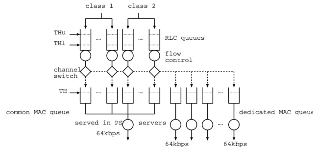
Figure 6 represents the model structure of the dynamic channelswitching system. Two stage
queues, comp osed of RLC and MAC queues, are provided in the gure. We note that MAC
MACqueues is limited,since the numb er of dedicated channelsis xed.
Eachof RLC queues has a buer with capacity C
r
frames. Each of dedicated MAC queues
has a buer with capacity C
m
frames. The common MAC queue has as many buers with
capacity C
m
frames asRLC queues.
Frames in each stream arrive at their own RLC queue. If a dedicated channel is allo cated
to astream, frames inthe stream are deliveredto theirown buer of a dedicated MACqueue
from RLC queue. If the common channel is allocated to a stream, frames in the stream are
delivered toits own buer of the common MAC queue fromRLC queue.
Furthermore,dynamicchannelallocationsarep erformedasfollows. Allstreamsareallocated
to the common channel at rst. The channel typ e allocated to a stream is switched from the
commonchanneltoadedicatedchannelifthe RLCqueuelengthismorethanTHu,giventhat
an available dedicated channel exists. A channel switching from a dedicated channel to the
common channeloccurs ifthe RLCqueue lengthis lessthan THl.
Flow controlsare performedin the following way. If the queue length of the common MAC
queue exceeds TH, the ames owfrom the connected RLCqueue islimited.
THu THl
TH channel switch
servers
RLC queues
served in PS
flow control class 1 class 2
64kbps
64kbps 64kbps
dedicated MAC queue common MAC queue
Figure 6: Dynamic channelswitching model.
4.1.2 Assumptions on arrivals and services
Werst providesome assumptions onthe pro cesses ofarrivaland service times ineach queue.
A typical scenario for a fully utilized W-CDMA system includes a mixture of high-sp eed
packetdata users and low-rate voiceconnections. Thus, we considertwokinds of trac to b e
arrived(see Figure6). Theyare classiedintotwoclasses. Wethen assumethat the streamof
arrivalsto class j (j =1;2) followsa Poissonprocess withrate
j .
Letthe service time of aframe inadedicated MACbuer b eexp onentiallydistributed with
rate. WeassumethatframesincommonMACbuersareservedundertheprocessor-sharing
tob eexponentiallydistributedwith rate=N,whereN denotesthenumb erofactivecommon
MACbuers. Furthermore,when theowcontrolisnot performed,a frameinthe RLCqueue
departs from the queue before the next frame arrives, since the service time is less than the
interval of arrivals. Thus,the number of frames in a RLC queue increases onlywhen the ow
controlisp erformed. WethenassumethattheowfromaRLCqueuetotheconnectedcommon
MAC queue is stopped while the ow control being performed, and that a frame arrived at a
RLC queue are delivered to the connected common MACqueue onitsarrival.
It isanticipatedthat this model isto o complicatedtoanalyze. Thus,we provideanapprox-
imate mo del inthe following subsection.
4.2 Approximate model
4.2.1 Model description
Wepreviously stated that the numb er offrames ina RLCqueue increasesonly when the ow
controlisperformed. Thus,wesimplyregardthetwo-stagequeuesassingle-stagequeueswhose
capacity should be K =Cr+TH.
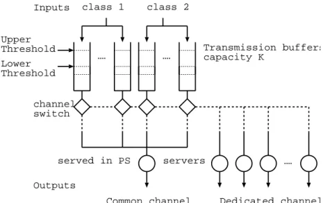
Now, we replace the model presented previously with the model shown in Figure 7. We
note that queues connected b etween RLC and MACare united in the approximate model. It
diersfromtheoriginalmodelastothelocationwherechannelswitchingisperformed,sincethe
channelsshowninFigure7aretob eswitchedinthefaceofservers. Butthe wholep erformance
of the model isexpected to be close to the original one. Thus, we will provide the analysis of
this mo del.
Inputs
Outputs Upper
Threshold
channel switch
servers
Transmission buffers capacity K
served in PS
class 1 class 2
Common channel Dedicated channel Lower
Threshold
Figure7: Approximate model.
Wenowconsidertwoclassesof arrivalpro cessesasshown inSection4.1, and xthe numb er
of class j streams to N
j
(j = 1;2). The number of buers is N
1 +N
2
. The capacity of each
![Figure 1 shows the general system architecture of UMTS outlined in [2]. It includes UEs,](https://thumb-ap.123doks.com/thumbv2/123deta/7309469.2421547/5.892.257.684.536.754/figure-shows-general-architecture-umts-outlined-includes-ues.webp)