九州大学学術情報リポジトリ
Kyushu University Institutional Repository
Petrogenesis of the Metacarbonatite Rocks from Amesmessa Area (In Ouzzal Terrane), Hoggar
Shield, Algeria
シェールバル, ムラド
http://hdl.handle.net/2324/2236219
出版情報:九州大学, 2018, 博士(工学), 課程博士 バージョン:
権利関係:
Algeria
Submitted by
CHERBAL MOURAD
A dissertation submitted in partial fulfillment of the requirements for the degree of
Doctor of Engineering in Economic Geology Supervised by Prof. Koichiro Watanabe
Department of Earth Resources Engineering Graduate School of Engineering
Kyushu University Fukuoka, Japan
January 2018 Fukuoka, Japan
i
Abstract
REE are generally considered to be the most critical of elements, indispensable for many high-tech applications such as smart-phones and electric vehicles. Currently, carbonatites are the main source of REE due to their high REE grade, especially that of LREE. However it is challenging to identify carbonatite rocks in metamorphic context. Indeed, the difficulty of distinguishing between metamorphosed carbonatites and metamorphosed limestones (or dolomites) in the field can lead to the misidentification of carbonatites in metamorphic belts.
In this respect, geochemical features of rocks, Sr and REE contents are distinctive to distinguish probable carbonate protolith, whether these rocks were carbonatite, or in fact limestone converted to marble. This thesis presents new findings on REE mineralization at the Amesmessa carbonatite, located in the In Ouzzal Terrane, western Hoggar, Algeria. This area is recognized as hosting Archean rocks, composed of two units dated to 3.5–2.7 Ga. The lower crustal unit is made up essentially of acid and basic granulitic gneisses of magmatic origin (charnockitic gneisses, anorthosites and norites. The supracrustal unit comprises quartzites, marbles, banded iron formations (BIF), Al–Mg and Al–Fe granulites commonly associated with mafic and ultramafic lenses. This study focuses on sampled metacarbonates from the Amesmessa area, employing field relations and a geochemical approach on whole rock, complemented with petrological and mineralogical methods in order to constrain petrogenesis. The petrogenesis of the Amesmessa metacarbonate rocks, which have previously been interpreted as marbles of Archean age, are reconsidered in the present study.
The results of this study are presented in this dissertation and consist of six chapters:
Chapter I states the significance of this study, aims and objectives, giving an outline of the chapters content and explains the methodology.
Chapter II reviews the classification, composition, occurrence and genesis of carbonatites;
the properties and uses of REE; different types of REE deposition; and the current state of knowledge in the transport and enrichment of the REE from the mantle to formation of ore deposits.
i
terrane in greater detail. Finally, the main features of the Amesmessa area are summarized.
Chapter IV describes field evidence assembled during field work and presents interpretations for the Amesmessa metacarbonate to illustrate relationships between Amesmessa metacarbonates, faults and country rocks. The Amesmessa occurrence, comprising carbonatite, syenite, pyroxenite, anorthosite and rhyolite, intrudes clearly charnockites and the granulite basement. Syenites and pyroxenites represent the major portions of the complex, with pyroxenites occurring at the core and syenites forming a near sigmoid structure around the carbonatite body. Anorthosite exposures are seen at several places in the pyroxenite body. Small boulders of carbonatite, probably representing stocks or plugs, are spread throughout pyroxenitic and syenitic bodies. The carbonatites also occur as small dykes varying in width between 40 cm and 1m; veins (fracture fillings that are 5–20 cm in width), and lenses up to 3 m long. Outcrop evidences obtained from the spatial and cross- cutting relations are decisive criteria for establishing the origin of the Amesmessa metacarbonate. This study suggests that the Amesmessa metacarbonates are an intrusive phase, based on (i) the spatial association of ultramafic, syenite and carbonate rocks, an ellipsoidal shape surrounded by granulitic rocks, (ii) simple cross-cutting relationships and structural relations from field observations, (iii) Lensoid and dike-shaped bodies of metacarbonate rock, (iv) contacts between metacarbonate and inclusions exhibit signs of reaction, suggesting fenitization. In two outcrops of the ultramafic rocks, the one enclosing carbonate rocks displayed severe hydrothermal alteration, which was possibly caused by the intrusion of carbonate melt, (v) Abundant mafic to ultramafic xenoliths of different sizes, which can be rounded or angular in shape within the metacarbonate, enveloped during the development and solidification of metacarbonate rock. The enclaves are always of meta- plutonics (country rocks: granulite, charnockites and mafic–ultramafic rocks), and not of metasedimentary origin. Samples were collected from all the rock units described above.
The chapter also describes petrographic examination and mineral identification in thin sections. The metacarbonate rocks consist of calcite, biotite, clinopyroxene, hornblende, olivine and apatite. The Amesmessa carbonatite shows abundant evidence of deformation. It
i
has been deformed and metamorphosed which is most obvious in carbonate microstructures and in phlogopite. Calcite is present in all thin sections of the metacarbonate samples. It forms granoblastic aggregates with coarse-grained texture exhibiting twinning and polygonal mosaic textures, most certainly recrystallized. Initial response to stress in metacarbonate rocks includes bent and segmented thin mechanical twinning lamellae in calcite overprinted by thick straight lamellae produced probably during compression. With increasing strain, twin lamellae grow thicker, develop bent or lenticular shapes. Phlogopite also exhibit bending, indicating their transport in a crystal mush.
Chapter V discusses the whole-rock composition of Amesmessa metacarbonate and surrounding rocks. The results are compared to other worldwide deposits. The data presented illustrates that the Amesmessa metacarbonates have many of the petrologic and geochemical characteristics of typical carbonatites, such as elevated LREE, Sr, Ba and Y content. Their chondrite-normalized REE compositions show similar patterns with typical carbonatites. The average total REE concentration in the metacarbonate is up to 5,700 ppm. However the associated rocks; syenite and pyroxenite contain only 60 and 12 ppm, respectively. Sr concentration is also high (>1,390 ppm) which is normally high in carbonatitic rocks and low in marbles. In this work, the highest levels of light lanthanides (up to 7775 ppm) were detected in samples with abundant calcite and apatite. A comparative study has been done to compare the obtained data with that of well-known metamorphosed carbonatites, together with marbles from different localities. The results reveal an overlap of compositions and provide distinctive features for either a sedimentary or igneous origin. On the basis of available chemical analyses and outcrop evidence, it becomes clear that the Amesmessa metacarbonate rocks consist of metamorphosed carbonatite.
Finally, Chapter VI is a discussion based on the previous 5 Chapters. It discusses the effects of metamorphism and summarizes the results and relates them to the aims and hypotheses of the thesis. The implication from this study are various and of relevance for the igneous and metamorphic petrology of carbonatites, and for wider settings in the entire Hoggar region.
The thesis concludes with suggestions for further work that would extend knowledge and understanding of metamorphosed metacarbonatites. This is a major finding because carbonatites have been described so far only in the northern part of the In Ouzzal
i
v
Acknowledgements
Completing a PhD is truly a marathon event, and I would not have been able to complete this journey without the aid and support of countless people over the past three years. I must first express my gratitude towards my advisor Professor Koichiro Watanabe. His leadership, support, attention to detail, hard work, has been of great help and motivation for my present and future work. Prof. Watanabe gave me the opportunity to study in the laboratory of Economic Geology at Kyushu University. The friendly and supportive atmosphere inherent to the whole Laboratory of Economic Geology contributed essentially to the final results of my studies. In this context I would like to thank particularly professor Akira Imai for his help and discussions, Associate professor Kotaro Yonezu and assistant professor Thomas Tindell for their fruitful comments and help.
I would like to express my sincere gratitude to the Japanese Ministry of Education, Culture, Sports, Science and Technology (Monbusho) who has supported my study in Kyushu University.
I am grateful to my Japanese colleagues and friends for their help and assistance in my daily life in Japan. I thank also my foreign friends, especially in Economic Geology Laboratory, for their help and support during my study in Japan.
I’d like to present my sincere thankfulness to my dear mother and my deceased father, who passed away during my stay in Japan, for their great role in my life and their numerous sacrifices for me and for my brothers. Many thanks for my brothers for their support and for being truly brothers when needed.
Last but not least, I’d like to express my deepest gratitude to my wife, Khadidja Ait ramdane, for her patience and tolerance over the last three years. Khadidja I could not be able to finish this work without your support. Thank you for being with me and for your appreciated sacrifices. Thank you my cute little son, Abdessalam, and my newborn baby, Aya, for being good kids with your mother when I was studying in Kyushu University.
vi
Acknowledgements v
Contents vi
List of Tables vii
List of Figures ix
List of Abbreviations xiii
List of Acronyms xxix
Chapter 1 Background, aims and methodology
1.1 Introduction 1
1.2 Significance of the study 1
1.3 Aims and Objectives 2
1.4 Thesis structure 3
Chapter 2: Carbonatites and Rare Earth Elements Deposits
2. 1 Carbonatites 4
2.1.1 Classification 4
2.1.2 Composition 5
2.1.3 Occurrence 6
2.1.4 Petrogenesis 6
2.2 Rare earth elements 8
2.2.1 Definition 8
2.2.2 Chemical characteristics 9
2.2.3 Abundance 10
2.2.4 Mineralogy 11
vi
2.2.5 Importance of the REE 12
2.2.6 Importance of the HREE 13
2.3 REE deposits 14
2.3.1 Carbonatites 16
2.3.2 Alkaline Rocks 17
2.3.3 Placer deposits 17
2.3.4 Ion-adsorption deposits 18
2.3.5 Other deposit types 18
2.4 REE in the mantle 19
2.5 Magmatic enrichment of REE 20
2.6 REE transport 21
2.6.1 Stability of different aqueous REE complexes 21
2.6.2 Solubility of REE minerals 26
2.6.3 Y/Ho fractionation and the tetrad effect 31
2.6.4 The chemistry of REE-bearing fluids 33
2.6.5 Current REE deposit models 44
2.7 Supergene REE enrichment 48
2.8 Summary 48
Chapter 3: Geological background
3.1 Introduction 51
3.2. Geology of the Hoggar 52
3.2.1 Introduction 52
3.2.2 Classical subdivision of the Hoggar 54
3.2.3 Terranes structuring of the Hoggar 55
3.3 Geology of the In Ouzzal terrane 57
3.3.1 Introduction 57
3.3.2 The In Ouzzal terrane 57
3.3.3 The dome and basin pattern of the In Ouzzal terrane and the eburnean tectonic 59
vi Chapter 4:Field Relations and Petrography
4.1 Introduction 63
4.2 Field Relations 63
4.3 Petrography 66
4.3.1 Amesmessa metacarbonatite 66
4.3.2 Country rocks 67
Chapter 5: Whole-rock geochemistry
5.1 Introduction 75
5.2 Methodology 75
5.3 Results 76
5.4 Interpretation 81
Chapter 6: Discussion and Conclusions
6.1 Effects of metamorphism 85
6.2 General conclusions 89
6.3 General implications 91
6.4 Further work 92
References 94
List of Tables
vii
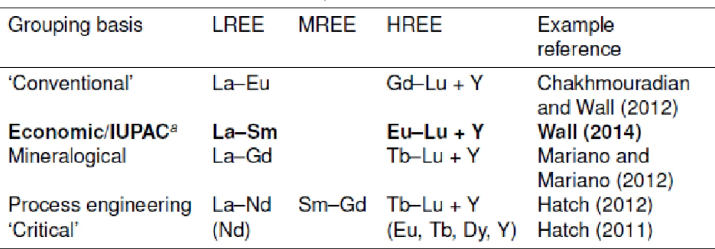
2.1 Atomic number, radii, symbol and abundance of the REE
2.2 Definitions of the LREE, MREE and HREE used in the literature on this thesis 2.3 Some common REE minerals
2.4 Uses of the REE
2.5 Advantages and disadvantages of different REE-deposits
2.6 Anion concentrations of carbonatite- and granite-derived REE-bearing fluids
2.7 Summary of the mineralogy and fluid-inclusion data from hydrothermal REE deposits.
4.1 Representative mineral assemblages of studied rocks with approximate abundance.
4.2 Representative chemical composition of country rocks of the Amesmessa metacarbonate.
5.1 Representative chemical composition of the Amesmessa metacarbonate.
5.2 Rare earth elements (ppm) composition of Amesmessa metacarbonate and marbles.
ix 2.1 Le Bas carbonatite model
2.2 Concentration of the REE in the continental crust 2.3 Prices of the REE
2.4 Spatial distribution and REE tonnages of the different types of REE deposit 2.5 Schematic of different types of carbonatite-related ore deposit
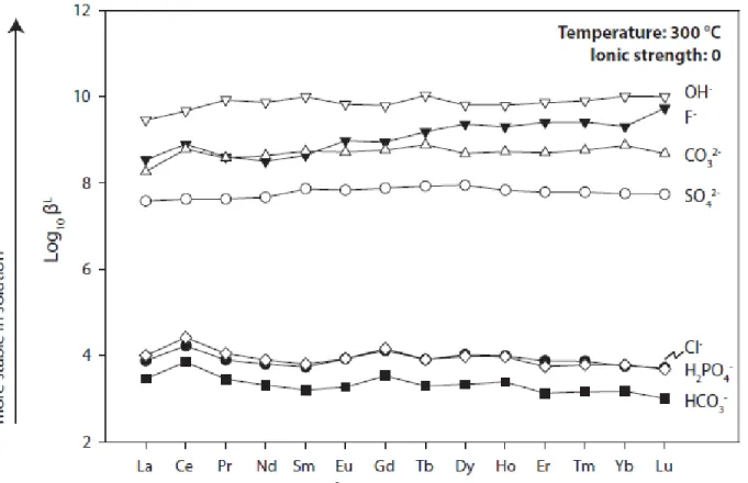
2.6 First formation constants of different REE ligands at ambient temperature 2.7 First formation constants of different REE ligands extrapolated to 300 ˚C
2.8 Experimentally-derived first formation constants for REE complexes between 100 and 300 ˚C
2.9 Experimentally-derived equilibrium constants for dissolution of NdPO4 and REEF3
2.10 REE concentrations in natural fluids normalized to chondrite
2.11 REE concentrations from fumarolic encrustations at Oldionyo Lengai
2.12 Temperature and pressure ranges of common REE-bearing minerals found in carbonatites
2.13 Schematic of REE speciation in a hypothertical hydrothermal fluid 3.1 Tectonic versus intraplate topographic highs of North Africa.
3.2 Schematic structural map of the Hoggar massif and adjacent areas.
3.3 Geodynamic and structural context of the Hoggar (Liégeois et al. 2012).
3.4 Geological map of the Tuareg Shield, showing the major structural domains and the repartition of the gold occurrences (Saadia Ysbaa et al. 2015)
3.5 The 23 terranes of the Tuareg shield from east to west.
3.6 Geological map of the Amesmessa area (modified from Djemai, 2008) showing the location of the Amesmessa metacarbonate.
4.1 Schematic interpretation of the Amesmessa metacarbonate geology showing the sample location (original data).
List of figures
ix
4.2 Exposure of Amesmessa metacarbonate. a) Carbonate infilling pyroxenite. b) Metacarbonate dike. c) Interaction of the metacarbonate with the enclaves fragments showing contact zone (fenitization?) which is a characteristic contact process that accompanies intrusions. d) Carbonate dike currying xenoliths of mafic rocks (pyroxenite) up to 30 cm in size. e) Filling fracture of metacarbonate with brecciated texture cutting pyroxenite. f) Brecciated texture showing diopside and phlogopite.
4.3 (A, B) representative rock samples of Amesmessa metacarbonatite; (C, D) Photomicrographs of the Amesmessa metacarbonatite (AM-033& AM-034 respectively). Ap, apatite; Cal, calcite; Ol, olivine; Phl, phlogopite.crossed nicols.
4.4 (A, B) Representative rock samples of glimmerite and syenite with coarse grained texture (upper photos). (C, D) Photomicrographs of the mica-rich rock (AM-046).
Qtz, quartz; Ser, sericite; Mag, magnetite. Crossed nicols.
4.5 (A, B) Representative rock samples of pyroxenite associated with the metacarbonatite. (C, D) Photomicrographs of pyroxenite (AM-044) showing thin Exsolution lamellae in pyroxene. Mag, magnetite; Px, pyroxene, Ol, Olivine, Opx,orthopyroxene; Cpx, clinopyroxene. Crossed nicols.
4.6 (A) Representative rock sample of Rhyolite. (B,C,D) Photomicrographs of rhyolite (AM-045). Qtz, quartz; Pl, plagioclase; Fsp, feldspar; Ms, muscovite. Crossed nicols.
4.7 Photomicrograph of carbonate rock from Amesmessa, (A) showing large spinel (Spl) having a reacted rim of magnetite (Mag) in contact with calcite, (B) showing Olivine (Ol) in the process of serpentinization in a carbonate matrix. Cal, calcite; Mag, magnetite; Spl, spinel; Ol, olivine; Srp, serpentine.crossed nicols
4.8 Photographs of representative polished hand specimens of carbonatite from the Amesmessa area. (A to E) The modal contents of silicates decrease and those of carbonates increase continuously from wall rock to carbonatite.
5.1 composition of carbonatite from Amesmessa plotted on the Woolly and Kempe’s (1989) CaO-MgO-FeO*(FeO*=FeO+MnO) diagram (wt. %).
5.2 (A) SiO2 vs. CaO diagram for Amesmessa metacarbonate (modified from Woolley and Church, 2005). (B) Diagram of (Sr + Ba) vs. (REE + Y) for Amesmessa
carbonate-rich rocks. Fields reproduced from Samoilov (1991). Abbreviations: CC=
Calcio-cabonatite; MC= Magnesio-carbonatite.
5.3 Y-Sr plot of Amesmessa metacarbonate and other carbonatites and marbles.
ix
compared with the average calico-carbonatite (Wooly & Kempe, 1989), world-wide Precambrian carbonatites and Precambrian sedimentary carbonates
6.1. Photomicrographs of metamorphosed carbonatite from Amesmessa area. Calcite is present in all sections. (a) Mosaic polygonal texture in calcite carbonatite and the development of diopside (di). Also present is olivine (Ol); (b) Bent and segmented thick twinning lamellae in calcite (cal) overprinted by thin straight lamellae produced during decompression (Pieri et al.2001); (c) Scattered phlogopite blasts in calcite matrix; (d) Primary (or weakly recrystallized) polygonal texture composed of calcite and phlogopite (Phl), note bending of the phlogopite crystals indicating their transport in a crystal mush. All photographs are taken with crossed-nicols.
6.2. Schematic illustration of the effects of deformation on the homogeneity and distribution of primary mineralization in carbonatites. a. Carbonatite intrusion containing traceable ore horizons prior to deformation. b. Deformed carbonatite body with multiple ex situ carbonatite dikes, large- and small-scale heterogeneities in carbonatite composition and texture, and greatly modified ore distribution. (A.R.
Chakhmouradian et al, 2015).
List of abbreviations
xiii
Abbreviations for mineral names used in this dissertation follow the recommendations of SCMR (Systematics of Metamorphic Rocks).
Symbol Mineral name Symbol Mineral name
Chl Di Ol Phl Srp
chlorite diopside olivine phlogopite serpentine
Cal Spl Pcl Ap Cpx
Calcite Spinel Pyrochlore Apatite
Clinopyroxene
xxix Acronym Explanation
PPL XPL SEM BSE EDX HFSE LILE REE
OIB MORB HIMU EM GIS SMC LATEA I.O.T I.G.U IOGU EIOSZ PALSAR ScanSAR FBS
plane polarized light (in transmitted light microscopy) crossed polars (in transmitted light microscopy) scanning electron microscope
backscattered electron energy-dispersive X-ray
high field strength elements (Nb, Ta, Zr, Hf, Ti) large ion lithophile elements (K, Rb, Cs, Sr, Ba, Pb)
rare earths elements (La, Ce, Pr, Nd, Pm, Sm, Eu, Gd, Tb, Dy, Ho, Er, Tm, Yb, Lu)
oceanic-island basalts mid-oceanic ridge basalt
high mantle (with high isotopic ratio of 238U/204Pb) enriched mantle
geographical information system Saharan Meta Craton
fourth terranes of Archaean age and Paleoproterozoic: Laouni, Azrou-n-Fad, Tefedest and Eger-Aleksod
In Ouzzal Terrane Iforas Granulitic Unit In Ouzzal Granulitic Unit East In Ouzzal Shear Zone
Phased Array type L-band Synthetic Aperture Radar
Synthetic Aperture Radar (depending on the number of Scans) Fine Beam Single polarization
Chapter 1: Background, aims and methodology
1
1. 1 Introduction
This chapter states the aims of the thesis and gives an outline of the chapter content and the methodology used. Later chapters contain more detail on the analytical techniques.
1. 2 Significance of the study
Carbonatites are igneous rocks comprising greater than 50 % carbonate minerals. They are very high grade and high tonnage REE sources, but most are typically LREE -rich and relatively HREE -poor (chapter 2; Wall, 2014).
The REE are a geochemically-similar group of elements composed of the lanthanoids (excluding scandium) and yttrium. They are considered by many to be among the most
‘critical metals’. These are metals which are of growing economic importance but for which there is a risk of supply disruption (e.g. Fig. 1.1). The production of critical metals is generally restricted to a few countries and they are not readily substituted in many of their applications. Furthermore, global recycling rates are low.
More than 90 % of the global REE production is from China (Humphries, 2013). In recent years there have been several changes in China’s REE export policies such that the long- term future of supplies to the West is uncertain. As a result there has been a surge in exploration for new deposits and a move to re-open old REE mines.
Most REE mines and many exploration projects exploit carbonatites or carbonatite related deposits.
Despite of all of this, the identification of carbonatite rocks in metamorphic context remains a matter of substantial debate and controversy. Indeed, the difficulty of distinguishing between metamorphosed carbonatites and metamorphosed limestones (or dolomites) in the field can lead to the misidentification of carbonatites in metamorphic belts.
In the present study, we propose to examine the petrogenesis of carbonate rocks (referred to locally as the Amesmessa metacarbonates.
2 Figure 1.1: The criticality matrix evaluated by the European Commission (2014), modified to show only the elements in the arbitrarily defined ‘critical’ part of the graph, with relatively high risk of supply disruption and economic importance. NB, scales are relative, criticality increases toward the top-right. PGM: platinum group metals. The REE are highlighted.
1. 3 Aims and objectives
The main objectives of the proposed research are to contribute new local data on the mineralogy and geochemistry of metamorphosed carbonatites, examine the effects of metamorphism on the mineralogy, and decipher the petrogenesis of the Amesmessa carbonate.
The field evidences were assembled during field work and presents its interpretations for the Amesmessa complex to illustrate relationships between Amesmessa metacarbonates, faults and wall rocks.
The geochemical data used to evaluate the whole rock composition was available from geochemical analyses which were conducted at Economic Geology Laboratory, Kyushu University.
This work focuses chiefly on the carbonatites, but various mafic and ultramafic rocks as well as regional marble in the Amesmessa area are also included and mineralogically examined
Chapter 1: Background, aims and methodology
3 (Chapter 4), since they may represent lithologies that are genetically related to the carbonatites.
1. 4 Thesis structure
In this Chapter 1, the themes and aims of the thesis have been presented and the identification of the hypothesis to be tested.
In Chapter 2, key definitions of carbonatites have been presented
In Chapter 3, the geological background of the study areas together with previous work are introduced.
Chapter 4 summarizes the field evidences assembled during field work and presents its interpretations for the Amesmessa Complex to illustrate relationships between Amesmessa Metacarbonates, faults and country rocks. The chapter continues by petrographic examination and mineral identification in thin sections.
In Chapter 5, the whole-rock composition of Amesmessa Metacarbonate and surrounding rocks are analyzed. The results are graphed, and compared to other occurrences of the globe.
Chapter 6 summarizes the conclusions, and relates them to the aims and hypotheses of the thesis. The thesis concludes with suggestions for further work that would extend knowledge and understanding of metamorphosed metacarbonatites.
4
This chapter reviews the classification, composition, occurrence and genesis of carbonatites; the properties and uses of the REE; the different types of REE deposit; and the current state of knowledge of the transport and enrichment of the REE from the mantle through to hydrothermal ore deposits.
2. 1 Carbonatites
More than 500 occurrences of the igneous carbonate rocks, carbonatites, are known. They are distributed globally, but often concentrated in stable, Precambrian, intra-plate cratons, along lineaments related to rifting (Woolley, 1989; Woolley and Kjarsgaard, 2008a). They are emplaced both intrusively and extrusively and can be temporally and spatially associated with a diverse range of (typically alkaline) silicate rocks (e.g. Woolley, 2001). The source region of carbonatites is debated, with some researchers favouring a lithospheric-mantle source on the basis of continued carbonatite and alkaline volcanism at the same site over geological time (e.g.
Woolley and Bailey, 2012), while others favour an asthenospheric mantle source based on isotopic data (e.g. Bell and Simonetti, 2010). Petrogenetic models for carbonatites are also diverse, with three different proposed mechanisms for carbonatite formation: (1) direct mantle melts, (2) liquid immiscibility from CO2 saturated silicate melts, and (3) residual melts of fractionated carbonated nephelinite or melilitite; combinations of these theories are also common (Jones et al., 2013). Once formed, carbonatites commonly evolve to higher Fe, REE and Sr contents (Le Bas, 1989). From an economic perspective, carbonatites can host several critical materials, such as the REE, niobium and fluorite as well as iron, copper, apatite and vermiculite and by-products such as barite, baddelyite, tantalum and uranium. The Phalaborwa carbonatite in South Africa also hosts significant PGEs, gold and silver (Mariano, 1989).
2.1.1 Classification
The IUGS2 defines carbonatite as an igneous rock containing at least 50 % modal carbonatite and less than 20 % silica (Le Maitre, 2002). This has been questioned on the grounds that it groups all rocks with more than 50 % carbonate together, despite an apparent diversity of origin. An alternative has been proposed where the system is split between igneous and “carbothermal”
carbonatite (Mitchell, 2005). In this system igneous carbonatite is defined as > 30 % carbonate, with no silica limit, with principal minerals prefixed in ascending order, while carbothermal residua should include a description of not only the rock, but also the antecedent. In this thesis the IUGS definition is used because of the igneous origin of the carbonatites studied.
Following the IUGS system, carbonatites are named first on the dominant carbonate mineral in the rock (Woolley and Kempe, 1989). These are as follows:
Calcite-carbonatite where the main carbonate is calcite, subdivided into:
• alvikite: medium–fine-grained calcite carbonatite
Chapter2. Carbonatites and Rare Earth Elements Deposits
5
• sӧvite: coarse-grained calcite carbonatite
Dolomite-carbonatite (Beforsite) where the main carbonate is dolomite Ankerite-carbonatite where the main carbonate is iron rich
Natrocarbonatite composed of sodium, potassium and calcium carbonate, and only found at Oldoinyo Lengai, Tanzania.
Failing mineralogical identification, similar nomenclature bands can be assigned based on whole rock modal CaO, MgO and (FeO + MnO) concentrations (Woolley and Kempe, 1989) or on calculated cation concentrations (Gittins and Harmer, 1997). These groups are calciocarbonatite, magnesiocarbonatite, ferruginous calciocarbonatite and ferrocarbonatite, respectively.
2.1.2 Composition
The major minerals in carbonatites are dominantly carbonates: calcite, dolomite and ankerite. The alkali carbonates, gregoryite and nyerereite, are limited to natrocarbonatites from Oldoinyo Lengai. Other minerals commonly present are apatite, magnetite, olivine, phlogopite, diopside and accessory pyrochlore, periclase, spinel, baddeleyite, fluorite, monazite and REE- fluorcarbonates.
The major elements in carbonatites are CaO, MgO, FeO, P2O5 and CO2, with variable concentrations of, SiO2, SrO, BaO, MnO and low concentrations of TiO2, Al2O3, K2O and Na2O.
The trace elements REE, U, Pb, Th, Nb, Sr and Ba are typically enriched, relative to primitive mantle. REE profiles of carbonatites, relative to chondrite, show strong enrichment in all the REE, especially the LREE, and display no Eu anomaly.
There is a general trend, in carbonatite composition, from early calcite-carbonatites through dolomite carbonatite to later ankerite carbonatite (Le Bas, 1989).
With this evolution the REE concentration increases, though it is not observed in all REE-rich carbonatite (e.g. Mountain Pass; Castor, 2008). During the later stage of carbonatite emplacement, as carbonatites transition from a magmatic to a hydrothermal regime, fluids are expelled from carbonatite (Rankin, 2005).
These fluids lead to REE, barite, strontianite and fluorite mineralization and carbonate veins.
6
2.1.3 Occurrence
Carbonatites can be emplaced both intrusively and extrusively. Intrusive carbonatites are the most common occurrence, found as dykes, ring dykes, cone sheets diatremes and subvolcanic pipes and plugs (Barker, 1989).
Extrusive carbonatites, first discovered in the 1960s (Dawson, 1962), are less well known. Only 10 % of carbonatites contain an extrusive component (Woolley and Church, 2005), although research into new extrusive carbonatite occurrences is expanding (Bailey and Kearns, 2012).
Most of these are pyroclastic, with lava flows known at only a few sites. The most famous carbonatite volcano is Oldoinyo Lengai in Tanzania. This is the only active carbonatite volcano and the only known locality where natrocarbonatite is found.
Most carbonatites occur surrounded by an alkali metasomatic aureole composed of fenite. Fenite is split into sodic and potassic varieties, both formed from fluids sourced from the intrusion.
Potassic fenite comprises K-feldspar, while sodic fenite comprises Na-rich amphibole with albite and K-feldspar. Younger carbonatite intrusions, with a shallow depth of erosion, are usually accompanied by potassic fenite, with a high degree of brecciation, while older intrusions, with a deeper erosion depth, generally are accompanied by sodic fenite, with much less brecciation (Le Bas, 2008).
Many carbonatites are intruded after various accompanying silicate rocks. These are commonly alkali-silicate rocks such as nephelinite-ijolite, nepheline syenite and syenite but carbonatites are also common accompanying kimberlite, lamprophyre and phoscorite (Krasnova et al., 2004;
Woolley and Kjarsgaard, 2008b). Carbonatites with no accompanying silicate rocks are also known, and the carbonatite–silicate connection is not well understood (Harmer and Gittins, 1997).
2.1.4 Petrogenesis Source
Radiogenic isotope ratios for 87Sr/86Sr and 143Nd/144Nd from carbonatites plot in a similar field to OIB, being more enriched (higher 87Sr/86Sr, lower 143Nd/144Nd) than MORB, spanning a range between HIMU (mantle with a high mu value) and EM1 (enriched mantle). The close similarity between carbonatites and OIB suggests the parental magmas are derived from a long-lived depleted mantle source, either from the lithosphere or sub-lithosphere (Bell et al., 1998; Bell and Tilton, 2001). Near-linear 143Nd/144Nd ratios with time suggest that enrichment in the LREE must have occurred at the time of magma genesis, either by immiscibility, vapour phase transfer or low degrees of partial melting in a garnet-rich source (Bell and Blenkinsop, 1989). Stable O, C and S isotopes are also indicative of a mantle source region (Deines, 1989).
Chapter2. Carbonatites and Rare Earth Elements Deposits
7
The processes of carbonatite emplacement between the mantle and the surface are the subject of debate with two main causes of partial melting commonly invoked. Isotopic signatures of carbonatite suggest a mantle plume component (Bell and Simonetti, 2010), while repeated intrusions at the same, cratonic, locations over large spans of geological time suggest a control within the lithosphere (Woolley and Bailey, 2012).
Genesis
Once a carbonate, or siliciocarbonate, melt has begun to form, there are three main theories regarding the genesis of carbonatite magma:
1. Residual melts of the fractional crystallisation products of carbonatite melilite or nephelinite magma (Gittins, 1989).
2. Liquid immiscibility between carbonate and silicate melts (Lee and Wyllie, 1997, 1998).
3. Direct formation of carbonatite in the mantle through partial melting of a CO2-bearing peridotite, and rapid ascent (Harmer and Gittins, 1997, 1998). In the first two models, a carbonated-silicate melt forms in the mantle, or at depth in the lithosphere, and ascends to the surface with little chemical reaction.
This liquid may then separate into silicate and carbonate portions, either by fractional crystallization or by liquid immiscibility. Alternatively, carbonate fluids can be produced by partially melting carbonated mantle peridotite at depth, forming magnesian carbonate. Upon ascent this would react with orthopyroxene present in lherzolite and harzburgite and undergo
‘chemical death’. However, it may be possible for a melt to avoid this by rapid ascent before equilibrium can be established or by forming and travelling through a metasomatic wherlite conduit (Harmer and Gittins, 1997, 1998). Various combinations of these models have also been proposed.
Evolution
Le Bas (1977, 1981, and 1987) devised a general petrogenetic model relating the nephelinite group of rocks to associated carbonatites, based predominantly on carbonatites from the East African Province (Fig. 2.1). This model has become the generally accepted carbonatite model. It suggests that carbonatites and associated nepheline-bearing rocks are the eroded cores of extinct nephelinite volcanoes.
The model favours the intrusion of carbonated nephelinite magma into the lower crust which undergoes immiscible separation into a volatile-rich liquid and a silicate liquid. Importantly, the volatile-rich fluid evolves, fractionates apatite and mafic silicates, and exolves Na- and K-bearing fluids to fenitise the country rock. This fluid rapidly ascends to the surface and produces carbonatite lavas and pyroclastics. If the carbonatite continues to evolve, it becomes more Fe-,
8
REE-, Sr- and Ba-rich, evolving from sӧvite, through alvikite, towards ferrocarbonatite.
Mineralizing fluids can cause successive deposits of the REE, fluorite, quartz veining and, lastly, U-Th deposition.
2.2 Rare earth elements 2.2.1 Definition
The REE comprise the 15 elements of the lanthanoid series of the Periodic Table, plus yttrium and scandium. In geochemical and mineralogical studies, promethium and scandium are excluded from this group as, respectively; they have no stable isotopes or behave markedly differently;
leaving a total of 15 elements (Table 2.1). The REE are grouped together because they exhibit similar geochemical characteristics and are difficult to separate from each other chemically. Such was the difficulty in separating them that it took approximately 150 years from the first isolation of ‘Yttria’ (itself a mix of Y, Tb and Er) to the isolation of all the individual REE, including Pm (Wall, 2014).
Figure 2.1: Petrogenetic model relating carbonatites to nephelinites, redrawn after Le Bas, 1987.
Chapter2. Carbonatites and Rare Earth Elements Deposits
9
Table 2.1: Names and symbols of the REE (after Henderson, 1996).
AN Symbol Name Radii
(nm)
Abundance (ppm) 39
57 58 59 60 61 62 63 64 65 66 67 68 69 70 71
Y La Ce Pr Nd (Pm)
Sm Eu Gd Tb Dy Ho Er Tm
Yb Lu
Yttrium Lanthanum
Cerium Praseodymium
Neodymium Samarium Europium Gadolinium
Terbium Dysprosium
Holmium Erbium Thulium Ytterbium
Lutetium
9.00 10.32 10.10 9.90 9.83 9.58 9.47 9.38 9.23 9.12 9.01 8.90 8.80 8.68 8.61
21.00 31.00 63.00 7.10 27.00
4.70 1.00 4.00 0.70 3.90 0.83 2.30 0.30 2.00 0.31
Radii are for REE with an VI coordination number; abundance is the concentration in the upper continental crust (after Rudnick and Gao, 2003). Promethium has no natural long-lived nuclei and, therefore, no natural abundance.
2.2.2 Chemical characteristics
The REE share similar geochemical characteristics because additional electrons are accommodated into the inner 4f shell, with the exception of Gd, La and Lu which are able to accommodate 1 electron into the 5d shell. As a result the REE, with two exceptions, maintain the same 3+ oxidation state. The two exceptions are Eu2+ and Ce4+ which can form under reducing and oxidizing conditions, respectively.
Different oxidation states of the some of the other REE are known, but seldom occur in nature.
The major difference between the properties of the REE is the systematic decrease in atomic radii across the group, known as the lanthanide contraction.
This is caused by the positive charge of the nucleus increasing with atomic number (and weight) while electrons added in the f orbital do not screen the other electrons from the positive pull. This contraction varies the size of the 3+ ion from 10.32 nm for La to 8.61 nm in Lu (Henderson, 1996). Yttrium has a similar 3+ charge and a cation radius of 9 nm and, thus, fits in the sequence between Dy and Ho (Table 2.1). This variation in ionic radius leads to the differentiation of the REE, by weight, into the LREE and HREE, with some also favouring an extra group, the MREE.
There is some variation in the definitions of each group (Table 2.2). Conventionally, the LREE
10
include La–Eu, and the HREE include Gd–Lu+ Y, although Eu is often included as a HREE by, for example, the IUPAC. Often economic geologists also favour the IUPAC definition because it is the approximate division between the REE of low and high value. Mineralogists prefer a boundary between Gd and Tb, where REE phosphates switch from a monoclinic (monazite) to a tetragonal (xenotime) structure. This is also the point where the REE switch from partially filled 4f orbitals to full 4f orbitals. Process engineers separate the REE into three groups based on the behavior of the REE during chemical separation. The term ‘critical’ REE is occasionally used to denote REE with the highest risk of supply disruption.
Table 2.2: Different definitions of the LREE, MREE and HREE used in the literature.
Also included are the ‘critical’ REE, which are so-called because these elements are predicted to be at the highest risk of supply disruption.
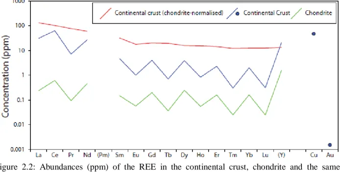
2.2.3 Abundance
The abundance of the REE in the continental crust decreases with increasing atomic number but the notion that the ‘rare’ earths are rare is false. The most abundant REE, Ce, is more abundant than copper and the least abundant REE, Lu, is more abundant than gold (Fig. 2.2). What makes the REE ‘rare’ is that chemical and geological separation of individual REE is difficult. This causes two problems: first, they are not easily concentrated into rich deposits, and the abundance is spread out across all of the continental crust; and, second, some of the REE are rarer than others meaning demand for a less-abundant REE will cause a more-abundant REE to be over- supplied.
Variation in the abundance of the REE is due to nucleosynthetic processes and the incompatibility of the LREE in the mantle during partial melting. The results of nucleosynthesis are best observed in the REE concentration of a C1 chondrite (Fig 2.2). Looking at the even- atomic-numbered REE (e.g. Ce, Gd, Yb) it is clear that the concentration of these elements decreases with increasing atomic number.
Chapter2. Carbonatites and Rare Earth Elements Deposits
11
Figure 2.2: Abundances (ppm) of the REE in the continental crust, chondrite and the same continental-crust concentrations normalized to chondrite. Values from Rudnick and Gao (2003);
McDonough and Sun (1995).
However, it is also clear that the concentration of these is much greater than the odd-atomic- numbered REE. This is due to the Oddo-Harkins effect, where odd-numbered nucleides are less stable than even-numbered ones, leading to a ‘zig-zag’ variation in abundance. Because of these effects it is common to normalise REE plots to chondritic meteorites (Fig. 2.2).
Chondrite-normalised REE distributions for the continental crust are LREE enriched. This is due to partial melting of the mantle and the varying cation size of the REE. During low-degree partial melting the larger LREE are much more incompatible in mantle minerals than the smaller HREE.
Therefore the HREE are retained in the source residue, while the LREEs enter the melt and ascend, becoming enriched in the crust.
2.2.4 Mineralogy
The REE are not found as native metals. They occur either as trace or minor constituents of other minerals or as REE minerals. Over 200 REE-bearing minerals are known. These occur as a wide range of types including borates, carbonates, oxides, halides, silicates, phosphates, arsenates, sulphates, vanadates, uranylcarbonates and uranyl-silicates. The most common and important of these are listed in Table 2.3. The most abundant REE in each mineral is indicated in parentheses e.g. xenotime-(Y), although the REE site will accommodate all of the REE to a low concentration. REE can also reach high concentrations in minerals where they easily substitute into other cation sites (e.g. Ca2+ in apatite and calcite) and these minerals can accommodate the bulk of the REE in rocks where REE minerals are not found.
12
Table 2.3: Some common REE minerals after Wall (2014)
2.2.5 Importance of the REE
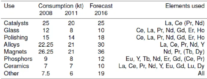
The REE are important both academically and economically. In geochemistry, the lanthanide contraction causes the REE to have smooth, systematic distribution coefficients with atomic number. This can be useful for modelling mineral or rock genesis. The presence and magnitude of Ce and Eu anomalies in the REE distribution can also be used to infer redox conditions during rock formation and, in the case of Eu, processes in the presence of plagioclase. The REE are also used in isotope geoscience for dating of rocks, modelling magma mixing and as an indicator of provenance.
Economically, the REE are used in a wide variety of high-tech applications, although often in small amounts; the total consumption of REE, worldwide, was 115,000 tonnes in 2012 (Wall, 2014). Demand for the REE has generally increased since the 1950s, but levelled-off between 2008–2011 due to the volatility in REE price (Table 2.4).
Chapter2. Carbonatites and Rare Earth Elements Deposits
13
Table 2.4: Uses and consumption of the REO (kt) in 2008, 2011 and forecast for 2016.
2008 data from Lusty and Walters (2011), 2011 and forecast data from Hatch (2012).
Projected REE requirements in the future, however, are set to increase, especially due to demand from REE permanent magnets for clean energy technology (Hatch, 2012; Alonso et al., 2012). In 2012 production of these magnets uses 20 % of the REE supply (Wall, 2014). Other uses for the REE include metal alloys, catalysts, polishing powders, phosphors, glass additives and ceramics (Table 2.4).
The REE are considered by many organizations to be a ‘critical metal’ e.g. the UK (Lusty and Walters, 2011), the EU (European Commission, 2014; Buchert et al., 2009), the USA (Long et al., 2010), and Australia (Hoatson et al., 2011).
In the case of the REE the main factor affecting its ‘criticality’ is the concentration of production in China. In 2010, about 97 % of global production was in China, although this fell to less than 90 % in 2014 as new mines came on stream (Henderson et al., 2011; Long et al., 2010). This is compounded by the difficulties of substituting the REE with other elements and the low REE recycling rates.
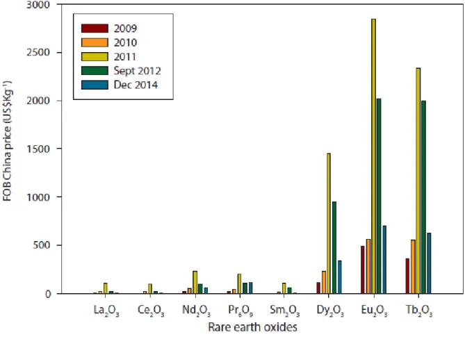
2.2.6 Importance of the HREE
The HREE can be considered as more ‘critical’ than most of the LREE because of their lower abundance (Fig. 2.2) and greater economic value. Specifically, all of the critical REE (Table 2.2), except Nd, are HREE. The high criticality of these elements is chiefly driven by demand in REE permanent magnets and phosphors.
The economic value of the REE is strongly influenced by their supply. There is an oversupply of the LREE (except Nd) and shortage of the HREE because of the LREE-rich nature of the upper crust and the rarity of geological separation of the REE. It is, therefore, predicted that the LREE will be oversupplied in the near future but the HREE will be under-supplied. These, unlike the
14
LREE, will maintain a high demand for at least 4 years (Hatch, 2011, 2012). The price difference between the REE reflects this factor: Ce oxide, for example, has a price of <$20 kg-1 while Eu oxide has a price of >$ 500 kg-1 (Metal-pages, 2014) (Fig. 2.3). The low consumption of the HREE, however, can cause these prices to fluctuate rapidly over a wide range.
Figure 2.3: Variations in the REE prices between the HREE and LREE since 2009. Data from Metal-pages (2014). FOB, Free On Board price, indicating the price of the oxide, plus transport and loading onto a ship for export.
2.3 REE deposits
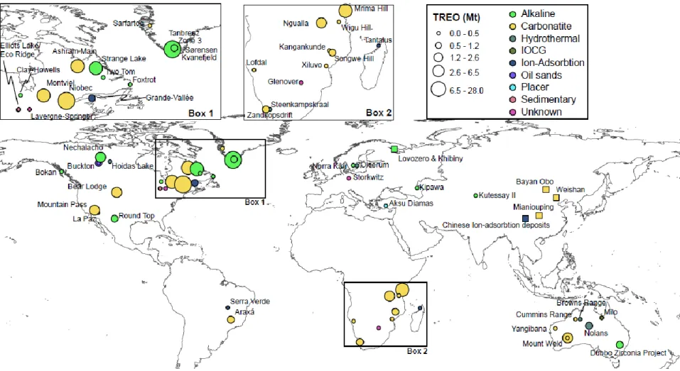
Demand for the REE, driven by the use of Nd-magnets and REE-phosphors, combined with a restriction in exports from China, has caused resurgence in exploration for REE deposits. As previously mentioned, the REE are not particularly rare, and this is reflected in the abundance of potential REE-deposits. Figure 2.4 demonstrates the worldwide distribution of REE exploration projects at the ‘advanced stage’ (those with a formally defined mineral resource or reserve), and
Chapter2. Carbonatites and Rare Earth Elements Deposits
15
Figure 2.4: Spatial distribution and REE tonnages (both resources and reserves) of the different types of REE-deposit at an advanced stage. Also included are the locations of important REE-deposits without tonnage data (square). Data sourced from Technology Metals Research (2015).
16
the total tonnage of REO available to be mined at these deposits. Also included are the locations of some of the major active and historic REE producing regions and, where possible, an indication of the amount of REO extractable from these deposits. It is clear from this figure that REE deposits are globally distributed and, considering that annual demand for the REE is approximately 150–170 kty-1 (Hatch, 2012), potential supply could far outweigh demand.
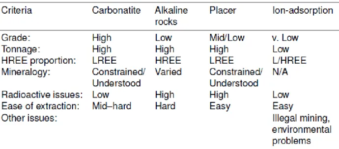
There are several different types of REE deposits, each with different characteristics. The main types are: carbonatite, alkaline rock, placer deposits and ion-adsorption deposits. Minor and un- utilized sources include hydrothermal deposits, IOCG deposits, mine waste and, looking into the future, sea floor and extra-terrestrial deposits (Kato et al., 2011; Taylor and Martel, 2003). There
are many deposits worldwide, the main characteristics which vary between them are grade, tonnage, REE distribution, environmental impacts, mineralogy, metallurgy, location, proportion of radioactive minerals, other environmental implications and economic factors, such as vertical
supply chain integration, available workforce, etc. (Table 2.5).
Table 2.5: Advantages and disadvantages of the major REE-deposit classes. N/A: no answer
2.3.1 Carbonatites
REE deposits in carbonatites are typically high grade and high tonnage deposits and the largest working (and worked) REE-deposits are all carbonatite related (Bayan Obo, China; Mountain Pass, USA; Mt Weld, Australia). The REE mineralogy varies between relatively simple, well- understood, minerals such as monazite and bastnӓsite, to much more complex and difficult to process minerals such as those of the crandallite group. Carbonatite-derived monazite is ubiquitously low in Th which is advantageous for transport and processing (Weng et al., 2013).
Carbonatites can also be major Nb and F sources, and, because of the ease of chemical weathering of carbonates, deep weathering profiles can form above carbonatites, causing residual
Chapter2. Carbonatites: An overview
17
enrichment in Nb and REE-minerals. The major disadvantage of carbonatite-hosted REE-deposits is their low HREE concentration and lack of an extractable HREE-bearing phase.
2.3.2 Alkaline Rocks
In this thesis the term ‘alkaline rock’ is applied sensu lato and covers all forms of Na- and K-rich and Si- and Al-poor intrusions. In these rock types the REE are enriched through a combination of low-degree partial melting and an extremely high degree of crystal fractionation. Furthermore, the most REE-rich alkaline intrusions usually feature autometasomatism, where intrusion-derived fluids react with the rock and further upgrade the REE concentration.
Alkaline igneous intrusion-related REE deposits are notable for having a high concentration of HREE, large tonnages and commonly an abundance of Zr, Nb, and U. Grades of the TREE are typically low, although they may still be economically favorable owing to the high–very high HREE contents. Mineralogically, alkaline intrusions can be very complex, often deceptively so, such that minerals which are, in theory, easy to process, such as eudialyte, are often pseudomorphed by much more complicated mineral assemblages (e.g. Coulson, 1997; Mitchell and Liferovich, 2006; Sheard et al., 2012). Furthermore, Th and U levels may be high in this deposit type, although this is not a universal feature. Other factors influencing the viability of an alkaline intrusion REE-deposit include the ‘hard-rock’ nature of the host intrusions, which would require extensive blasting and crushing, and the location. Some of the largest alkaline intrusions are in northern Canada, Alaska and Greenland. Access would require extensive road building or the construction of a deep-water port.
2.3.3 Placer deposits
Placer deposits include modern and palaeo heavy mineral sands. Historically, Indian beach sands were the main source of global REE supply prior to the development of Mountain Pass, in the USA, in the 1960s. The REE are found in the heavy minerals monazite and xenotime, which are commonly associated with ilmenite, rutile and zircon.
These deposits are low grade, generally large in volume, and the REE minerals can be extracted as a by-product of Ti and Zr. They are easy to work, requiring little to no crushing. Currently, however, at active mineral sand extraction operations, REE-bearing minerals are not extracted or stockpiled, and are re-buried in-situ. This is because of the high Th concentration in monazite which means any stockpiled monazite concentrate would be too radioactive to transport or process.
18
2.3.4 Ion-adsorption deposits
Ion-adsorption type deposits, mostly found in southern China, supply a large proportion of the global HREE demand. This deposit type, however, is one of the most favorable REE sources and well understood. Two factors are known to be required:
1. A deep, tropical weathering profile with low erosion rates
2. A readily-leachable REE mineral phase in the weathered host rock
Breakdown of REE-minerals in the parent rock releases REE, which adsorb via cation-exchange or chemisorption onto clay minerals such as kaolinite, halloysite and smectites in the deeply weathered zone. This process can enrich the weathered horizon in REE up to five times relative to the parent rock (Kynicky et al., 2012).
The grades and tonnages of ion-adsorption deposits are very low (0.05–0.2 wt. % REO; Kynicky et al., 2012). However, the deposits are easy to mine and in some cases can be mined in-situ with little need for heavy machinery. Their U and Th contents are also low. However, their exploitation in numerous smallscale pits over extensive areas and associated groundwater pollution has caused serious environmental damage. Ion-adsorption deposits are typically HREE rich but the REE distribution varies from LREE-enriched deposits to HREE-enriched deposits.
This is likely to be controlled by the REE distribution of the protolith (Sanematsu et al., 2013).
2.3.5 Other deposit types
Other potential REE sources include hydrothermal veins of unknown provenance (i.e. not related to a known intrusion; e.g. Steenkampskraal, South Africa, Andreoli et al., 1994), IOCG deposits (e.g. Olympic Dam, Australia), and by-products, co-products and waste sources.
The potential to extract REE as a co-product, a by-product, or from waste are particularly attractive. A co-product is defined as being of equal importance to the main product and intentionally produced as part of the same mineral-processing flowsheet. A by-product is a secondary or incidental product which can be refined after processing if it is technically feasible to do so and under favorable economic conditions. Waste is what remains when the commodities of interest have been removed. It can be, therefore, enriched in other metals which were not targets of the primary extraction.
Phosphate extraction is a favorable source for REE co- or by-product extraction (Emsbo et al., 2015). It is extracted from both sedimentary and igneous sources for use in fertiliser, and extraction of the REE could take place during processing of these rock types. For example, Simandl (2014) calculated that 70 kt of REE could be extracted annually from worked sedimentary phosphorite deposits. Apatite could also be a potential by-product from Kiruna-type
Chapter2. Carbonatites: An overview
19
iron-ore deposits, the Khibiny apatite mine, and from apatite waste from Mineville, USA (Ihlen et al., 2014; Mariano and Mariano, 2012).
Other potential by-product REE sources include extraction during Nb production from loparite at Lovozero, Russia (Wall, 2014); and as a by-product of uranium mining (Simandl, 2014). Other potential waste sources include red muds from aluminium production, xenotime from tin production at Pitinga, Brazil, U-ore tailings in Kazakhstan (Wall, 2014), and possibly from coal ash (Seredin and Dai, 2012).
2.4 REE from the mantle to a carbonatite-hosted ore deposit— sources of REE in the mantle
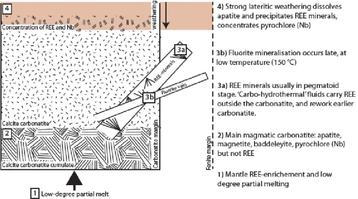
In the following sections the processes that lead to the formation of REE ore deposits in carbonatites are discussed. Schematically, the subdivisions of each stage are shown in Figure 2.5.
The sources of REE in the mantle, and the effects of magmatic processes on the REE are covered.
Most REE-deposits are either hydrothermally derived, or have a strong hydrothermal overprint, and, therefore, this section is most thoroughly reviewed. Finally, the formation of supergene deposits is briefly covered.
Mantle metasomatism, where materials are added to the mantle by either diffusion or through the infiltration of another phase, is widely acknowledged as a requirement in enriching the mantle in the REE and other incompatible elements (Chakhmouradian and Zaitsev, 2012). This can occur through transport in CO2-bearing fluids, supercritical aqueous fluids or in hydrated silicate melts (Meen et al., 1989).
As previously discussed, LREE-enrichment in melts is largely due to the incompatibility of the LREE in mantle minerals, and thus these metals will preferentially be incorporated into the melt during partial melting. Candidate minerals for providing the majority of the REE into the melt include silicates, such as clinopyroxene, amphibole and phlogopite, or less common minerals, such as apatite or titanate minerals of the chrichtonite series (Jones and Ekambaram, 1985; Jones, 1989; Wyllie et al., 1996; Hammouda et al., 2010).
20
Figure 2.5: Schematic diagram of different types of carbonatite-related ore deposit, caused by partial melting (1), magmatic (2), hydrothermal (3) and supergene (4) processes.
2.5 REE from the mantle to a carbonatite-hosted ore deposit— magmatic processes
Melts formed by melting from a metasomatised mantle are commonly emplaced in intracontinental, anorogenic, extensional settings. Fractionation of REE-poor minerals is required to enrich REE in the melt, as direct mantle melts do not have sufficiently high REE concentrations to produce an ore deposit. In carbonatites, the common association of these rocks with clinopyroxene-magnetite and olivine-magnetite rocks supports the hypothesis that enrichment of the REE in a carbonatite melt can occur through simple fractionation of silicate phases. However, the presence of apatite as early ovoid grains and the occurrence of phoscorites (magnetite-olivine-apatite rocks; Krasnova et al., 2004) with some carbonatites demonstrates that apatite can also fractionate from a carbonatite melt. The REE readily substitute into apatite, and fractionation of apatite from a carbonatite melt is likely to lead to a REE-poor carbonatite.
An alternative means of REE enrichment, if the carbonatite formed through liquid-immiscibility from a carbonated silicate melt, is through preferential partitioning of the REE into a carbonatite melt. However, experimental work shows that this does not occur and, upon silicate and carbonatite melt separation, the REE preferentially partition into the silicate phase (Veksler et al.,
Chapter2. Carbonatites: An overview
21
2012). Carbonatite enriched in the REE can produce primary magmatic REE minerals. Primary magmatic mineralization is rare, but a notable example is crystallization of bastnӓsite-(Ce) at Mountain Pass, California (Mariano and Mariano, 2012). An experimental work on the system CaCO3–Ca (OH) 2–La (OH) 3 and CaO–La2O3–CO2–H2O shows that bastnӓsite can crystallize at shallow crustal depths to temperatures as low as 550 C° (Wyllie et al., 1996). Another example of a magmatic REE mineral, supported by isotopic data, is burbankite-(Ce) (Zaitsev et al., 2002).
This can form crystals up to several cm in size in pegmatites or small drop-like inclusions in carbonates. Burbankite is thought to commonly form in carbonatites, but is commonly pseudomorphed to strontianite, barite and REE fluorcarbonates by hydrothermal fluids.
2.6 REE from the mantle to a carbonatite-hosted ore deposit— REE transport in hydrothermal fluids
Most REE mineralization in carbonatites occurs as a result of transport and deposition of the REE in a hydrothermal fluid at a late stage in the evolution of a carbonatite. Understanding of the behavior of the REE in hydrothermal solution (i.e. conditions which make hydrothermal ore deposits) has improved considerably in the past 25 years. Far from being elements which are immobile in solution, it is now understood that, under some conditions, these elements are highly mobile and can lead to the formation of large REE ore deposits (e.g. Bayan Obo, China; Smith et al., 2014).
Mobility of the REE is a function of the stability of the possible aqueous complexes, the availability of ligands to form complexes, the solubility of REE minerals, and the temperature, pH and redox conditions of the fluid (e.g. Lottermoser, 1992; Gieré, 1996). Understanding the theoretical constraints of REE mobility and the composition of geological fluids where REE mobility has taken place is important to the understanding of how REE ore deposits form. Herein, the thermodynamic data and current knowledge of REE-bearing fluids are reviewed with respect to current REE ore deposit models.
2.6.1 Stability of different aqueous REE complexes
REE in solution invariably form complexes with anions; even when no anion is present the REE are surrounded by water molecules. The number of surrounding molecules (coordination number) of the HREE is 8, while for the LREE the number may be slightly higher (8–9) (Wood, 2003).
The strength of the interaction between the REE in solution and available anions can be compared for different anions by measuring the formation constant (syn: stability constant, binding constant).
22
This is the equilibrium constant for the formation of a complex in solution, denoted as β and is a function of the ratio of the concentrations of the ligands and metals in isolation and the concentration of combined ligands:
β= [ML] / [M][L] (2.1)
Where [M] and [L] denote the concentrations of the metal and ligands, respectively, and [ML]
denotes the combined concentration. Thus, the higher the value of β, the more stable the aqueous complex. In reality, more than one ligand can often bind to a metal, and, as such, the denotation βLn is more valid where:
Where, Mx, Ly and M Lx-(ny) represent the metallic cation, ligand and complex respectively, where x and y are the respective charges of each and n represents the number of ligands of superscript L in the complex. Thus, the formation constant of a first-order complex of the REE and Cl (REECl2+) would be denoted as βCl1, while a second-order complex (REECl+2) would be denoted as βCl2. These values are typically measured experimentally in a certain concentration of an acid, but to make the formation constants comparable between different solutions, they are, where possible, referenced to conditions of infinite molar dilution. Formation constants for the REE have been sourced by three techniques:
1. Ambient temperature stability experiments
2. Extrapolation of ambient temperature thermodynamic data to high (> 100 °C) temperature 3. Experimental measurements of thermodynamic properties at high temperature
Stability of aqueous REE complexes at ambient temperature
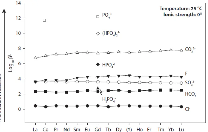
Thermodynamic data from ambient temperature analyses of the REE prior to 1990 were summarized by Brookins (1989); Wood (1990) and Millero (1992). These papers included stability constants for the REE with SO42-, F-, Cl-, OH-, NO3-, CO32- and HCO3-. Subsequent papers have refined the values for sulphate (Schijf and Byrne, 2004), fluoride (Schijf and Byrne, 1999; Luo and Byrne, 2000), chloride (Luo and Byrne, 2001), hydroxide (Klungness and Byrne, 2000), carbonate (Liu and Byrne, 1998; Luo and Byrne, 2004), and bicarbonate (Luo and Byrne, 2004) and new data for complexation by phosphate has been acquired (Byrne et al., 1991). The updated ambient temperature data are shown in Figure 2.6.
The analyses of complexation at ambient temperature show that the ‘hard’ (not polarizable), trivalent, REE cations preferentially bond with ‘hard’ (ionic) anions, in accordance with