JAIST Repository
https://dspace.jaist.ac.jp/
Title コンポーネントソフトウェア開発用軽量フォーマルメ
ソッドの研究
Author(s) 松本, 充広
Citation
Issue Date 2002‑03
Type Thesis or Dissertation Text version author
URL http://hdl.handle.net/10119/920 Rights
Description Supervisor:二木 厚吉, 情報科学研究科, 博士
Lightweight Formal Methods for Component-based Software Development
by
Michihiro MATSUMOTO
submitted to
Japan Advanced Institute of Science and Technology in partial fulfillment of the requirements
for the degree of Doctor of Philosophy
Supervisor: Professor Kokichi FUTATSUGI
School of Information Science
Japan Advanced Institute of Science and Technology
March 22, 2002
Copyright c2002 by Michihiro Matsumoto
Abstract
In the thesis, we discuss (1) lightweight formal methods for component-based software called LFMB and LFME, (2) the component-based software development using LFMB or LFME called CBDL, and (3) the support tools of CBDL. Recently, component-based software development has gained in popularity. In the development, firstly we prepare a component library whose components produce basic functionalities. Then, by select- ing components from the component library and by combining them using connectors, component-based software is developed. We call the parts of the software combining the components connectors. The reason for the popularity is that it can increase software productivity. To increase software productivity, components must be reused. The obsta- cles of component reuse are (a) a lack of a consensus about component usage between component developers and software developers, i.e. component users and (b) an archi- tectural mismatch. We developed CBDL to eliminate the obstacles. CBDL is based on the Catalysis approach. The former obstacle is eliminated by specifying business models and component specifications by using UML diagrams with OCL descriptions and verify- ing consistency in the UML diagrams. The former technique is an idea of the Catalysis approach. The latter technique, i.e. LFMB and LFME, is a contribution of the thesis.
Lightweight formal methods are formal methods such that they have target problems and they use simple logic that the verification of the problems can be executed automatically.
The consistency verification in the UML diagrams are the target problems of LFMB and LFME. Behavioral logic and equational logic are the simple logic of LFMB and LFME, respectively. So, LFMB and LFME are lightweight formal methods. Because LFMB and LFME include automated verification methods of the consistency, component developers and software developers who are not familiar with formal methods can get the benefit of the verification by using the support tools of CBDL. The latter obstacle is eliminated by selectingtree architecturethat we developed. We can regard the UML diagrams as specifi- cations specified bya language for programming-in-the-large. So, in CBDL, moreover, we generate component-based software from the UML diagrams by combining the connectors specified in the UML diagrams and components of a component library. Note that the above consistency verification guarantees the correctness of the connectors. Because the support tools of CBDL are designed as client-server type software, component developers and software developers can access to the tools through Internet at any place at any time.
To summarize, by using the support tools of CBDL, we can increase component reuse and correctness of component-based software.
Acknowledgements
First of all, I am grateful to my main supervisor Professor Kokichi Futatsugi who has not only provided valuable suggestions but also shown me the right direction of my study.
In addition, I thank LDL members, especially previous Associate Professor Takuo Watanabe, previous Associate Kazuhiko Ogata, previous Associate R˘azvan Diaconescu, previous Associate Akira Mori, Associate Noriki Amano, and Dr. Shusaku Iida for helpful discussions about my study.
A part of my study was carried out as the projects that were supported by grant Support program for young software researchers 99-004 and Support program for young software researchers 01-006 from Information-technology Promotion Agency (IPA) and Research Institute of Software Engineering (RISE). So, I thank Information-technology Promotion Agency and Research Institute of Software Engineering. Also, I thank the project members, Mr. Yoshihito Katayama, Mr. Takanori Nakama, and Mr. Yoshiharu Hashimoto.
Finally, I thank my employer PFU Limited, which supports my life at JAIST.
Contents
Abstract i
Acknowledgements ii
1 Component-based Software Development and Formal Methods 1
1.1 Component-based Software Development . . . 1
1.2 Formal Methods . . . 2
1.3 Applications of Formal Methods to Component-based Software Development 3 1.4 CBDL . . . 3
2 Preliminaries 7 2.1 The Catalysis Approach . . . 7
2.2 Algebraic Specification . . . 9
2.2.1 Signature, algebra, and term . . . 9
2.2.2 Homomorphism, equation, and satisfaction . . . 11
2.2.3 Specification and model . . . 12
2.2.4 A complete deduction system of equational specification . . . 13
2.2.5 Algebraic behavioral specification . . . 14
2.3 Abstract Reduction System . . . 15
2.3.1 Abstract reduction system . . . 15
2.3.2 Term rewriting system . . . 16
2.4 CafeOBJ . . . 16
2.5 JavaBeans and Servlets . . . 17
2.5.1 JavaBeans . . . 17
2.5.2 Servlets . . . 17
3 An Overview of CBDL 18 3.1 CBDL . . . 19
3.2 The Applications of Formal Methods in CBDL . . . 21
3.3 Tree Architecture . . . 22
3.3.1 Tree architecture . . . 22
3.3.2 Evolution of a component library . . . 23
3.4 AA-trees Model of Objects and Actions . . . 23
3.5 An Overview of LFMB . . . 24
3.6 An Overview of LFME . . . 24
3.7 An Overview of Connector Generation in CBDL . . . 24
4 Tree Architecture 26
4.1 Tree Architecture . . . 26
4.1.1 Event models . . . 26
4.1.2 Static structures . . . 27
4.1.3 Dynamic structures . . . 28
5 AA-trees Model of Objects and Actions 30 5.1 AA-trees Model . . . 30
5.1.1 Objects, associations, and attributes . . . 30
5.1.2 Actions . . . 31
5.1.3 Agents and data . . . 31
5.1.4 Agent decomposition . . . 32
5.1.5 Action decomposition . . . 33
5.1.6 Classes . . . 34
5.1.7 Business models . . . 35
5.1.8 Component specifications . . . 35
5.1.9 Static constraints . . . 36
5.2 The Guideline How To Specify AA-trees Models by using UML Diagrams with OCL Descriptions . . . 36
5.2.1 Classes, associations, and attributes . . . 37
5.2.2 Data class diagrams . . . 37
5.2.3 Basic class diagrams . . . 39
5.2.4 Action usecase diagrams . . . 41
5.2.5 Decomposition class diagrams . . . 43
5.2.6 Decomposition sequence diagrams . . . 45
5.2.7 Decomposition statechart diagrams . . . 45
6 A Verification Method of Equational Specification with = 46 6.1 Equational Specification with= . . . 46
6.2 A Deduction System of Equational and Inequational Specification . . . 48
6.3 Double Term Rewriting System with Condition . . . 53
7 LFMB 62 7.1 A Formalization of Tree Architecture by using Projection-style Behavioral Specification . . . 62
7.1.1 Data structures . . . 62
7.1.2 Event model of component . . . 63
7.1.3 Composite component . . . 64
7.1.4 Conditional component specification . . . 66
7.2 A Formalization of AA-trees Model of Component Specifications by using Projection-style Behavioral Specifications . . . 69
7.2.1 A formalization of AA-trees model of component specifications by using projection-style behavioral specifications . . . 69
7.3 Translation from UML diagrams into Projection-style Behavioral Specifi- cations . . . 70
7.3.1 Data class diagrams . . . 70
7.3.2 Basic class diagrams . . . 71
7.3.3 Action usecase diagrams . . . 71
7.3.4 Decomposition class diagrams . . . 73
7.3.5 Decomposition sequence diagrams . . . 74
7.3.6 Decomposition statechart diagrams . . . 74
7.3.7 Data specifications . . . 75
7.3.8 Primitive component specifications . . . 75
7.3.9 Component specifications . . . 75
7.4 Consistency Verification of UML diagrams . . . 75
7.4.1 Refinement verification . . . 75
8 LFME 77 8.1 A Formalization of AA-trees Model by using Equational Specifications . . . 77
8.1.1 Static structure . . . 77
8.1.2 Dynamic structure . . . 83
8.1.3 Conditional static specification and conditional dynamic specification 86 8.1.4 Business models . . . 87
8.1.5 Component specifications . . . 87
8.2 Translation from UML diagrams into Equational Specifications . . . 89
8.2.1 Data class diagrams . . . 90
8.2.2 Basic class diagrams . . . 90
8.2.3 Action usecase diagrams . . . 92
8.2.4 Decomposition class diagrams . . . 94
8.2.5 Static specifications . . . 96
8.2.6 Dynamic specifications . . . 96
8.2.7 Static invariants . . . 96
8.3 Consistency Verification of UML diagrams . . . 96
8.3.1 Refinement verification . . . 96
8.3.2 Verification of satisfaction of static invariants . . . 97
9 A Comparison between LFMB and LFME 98 9.1 Refinement Verification . . . 98
9.2 Logic of Projection-style Behavioral Specification . . . 100
10 Connector Generation 101 10.1 JavaBeans Implementation of Tree Architecture . . . 101
10.2 Automated Connector Generation . . . 102
10.3 Servlets with JavaBeans Implementation of Tree Architecture . . . 104
11 Support Tools 105 11.1 A Support Tool of CBDL using LFMB . . . 105
11.1.1 The structure of the support tool . . . 106
11.1.2 The functions of the support tool . . . 106
11.2 Support Tools of CBDL using LFMB and LFME . . . 107
11.2.1 The structure of the support tools . . . 107
11.2.2 The functions of the support tools . . . 108
12 Case Studies 112 12.1 The Domain of File Transfer Programs . . . 112
12.2 The Domain of Online Bookstores . . . 113
13 Conclusion 114
Bibliography 116
Publications 119
Projects 121
Chapter 1
Component-based Software
Development and Formal Methods
In the thesis, we discuss:
1. lightweight formal methods for component-based software calledLFMB (a Lightweight Formal Method using Behavioral specification) and LFME (a Lightweight Formal Method using Equational specification),
2. the component-based software development using LFMB or LFME calledCBDL (a Component-Based software Development approach using LFMB or LFME), and 3. the support tools of CBDL.
In Chapter 1, firstly, we discuss:
1. what component-based software development (abb. CBD) is, 2. what formal method is, and
3. what kinds of applications of formal methods to CBD have been studied.
Then, we discuss CBDL.
1.1 Component-based Software Development
Component-based software development has gained in popularity. Many developers use component technologies, for example, JavaBeans, COM, EJB, and CORBA[35].
In the development, firstly we prepare a component library whose components produce basic functionalities. Then, by selecting components from the component library and by combining them using connectors, component-based software is developed. We call the parts of the software combining the componentsconnectors.
The reason for the popularity is that it can increase software productivity. To increase software productivity, components must be reused. The obstacles of component reuse are:
1. a lack of a consensus about component usage between component developers and software developers, i.e. component users and
2. an architectural mismatch.
Because component developers and software developers usually do not know one an- other, it is difficult to get the consensus about component usage without a support means.
The software developers can not use the components without the knowledge about com- ponent usage. So, it is difficult to reuse components without the support means.
The Catalysis approach[12] is one of the support means. It uses UML diagrams with OCL descriptions[6] to help to get the consensus. The business concepts of the target domain are specified by using UML diagrams with OCL descriptions. The behavior of components are specified by using the business concepts. So, ambiguities about compo- nent usage are eliminated by the UML diagrams. We call the specifications specifying the business concepts business models and the specifications specifying behavior of the components component specifications.
The architectural mismatch problem[13] is the problem that components cannot be combined with components which have different software architectures. For example, user interface components which use X library cannot be combined with user interface components which do not use X library. So, it is difficult to reuse components without a common software architecture.
There are many researches about software architectures[2]. In CBD, we deal not with software but a software family. Product line architecture [3, 8, 30, 33] whose idea at least dates back to [31] is a software architecture for a software family. In the CBD whose software architecture is product line architecture, firstly, we fix a software family, i.e. a target domain and prepare a component library of the target domain. By selecting com- ponents from the component library and by combining them, component-based software of the target domain is developed.
We use architectural description languages (abb. ADLs) to specify software architec- tures. The idea of ADLs dates back to “programming in the large versus programming in the small”[9]. Programming in the small is programming for making modules. Program- ming in the large is programming for combining modules. The idea of programming in the large led to module interconnection languages (abb. MILs)[32] and ADLs.
From ADL specifications, we sometimes generates connectors that combine modules.
Generative programming[8] is one of the generation techniques.
1.2 Formal Methods
Formal methods are approaches of software engineering that use mathematics. The main instruments of the formal methods are specification languages. There are many specification languages, for example, Z[34], B[24], VDL[4], RAISE[18], OBJ3[17], and CafeOBJ[10]. Because specifications specified by using the specification languages are mathematical notations, we can verify properties of the specifications by using mathe- matical logic. Some specification languages, for example, B, VDL, RAISE, OBJ3, and CafeOBJ have verification systems for their languages.
The benefits of formal methods are as follows:
1. we can get clear understanding of a target software in the process of specifying the target software and
2. we can verify properties of the target software using the verification systems.
Unfortunately, the verification usually needs human help. So, it is difficult for non- specialists of the verification to get the benefit of 2. Lightweight formal methods are formal methods such that:
1. they have target problems and
2. they use simple logic that the verification of the problems can be executed auto- matically.
Because support tools that use the simple logic execute the verification automatically, the non-specialists can get the benefit of 2 by using the support tools.
The formal method using Alloy [22] is a lightweight formal methods. The purpose of Alloyis to propose the smallest modeling notation that is easy to read and write and can be analyzed automatically.
1.3 Applications of Formal Methods to Component- based Software Development
As we discussed in Section 1.1, the solutions of eliminating the obstacles of component reuse are as follows:
1. support means for getting the consensus about component usage and 2. selection of a common software architecture.
As we discussed in Section 1.2, formal methods can be the support means. By spec- ifying component usage by using specification languages, we can get the consensus. In fact, we can regard UML with OCL in the Catalysis approach as a specification language.
Note that the solution of the Catalysis approach is nothing other than an application of formal methods to CBD.
We can verify properties of the specifications by using the verification systems. The verification helps to get the consensus, too.
To specify the common software architecture, we can use specification languages. Note that we can regard ADLs as specification languages.
Because ADLs are specification languages, we can verify properties of ADL specifica- tions. Consider generation of connectors from the ADL specifications. By the verification, we guarantee the correctness of the connectors.
1.4 CBDL
We developed lightweight formal methods called LFMB (a Lightweight Formal Method using Behavioral specification)andLFME (a Lightweight Formal Method using Equational specification). CBDLis a Component-Based software Development approach using LFMB or LFME.
CBDL is based on the Catalysis approach. By using the Catalysis approach, we get the benefit of 1 of formal methods. But, because the verification is out of the scope of the Catalysis approach, we can not get the benefit of 2 by only using the Catalysis approach.
In the Catalysis approach, UML diagrams are specified by a number of software en- gineers. So, there may be inconsistencies in the UML diagrams. To eliminate the in- consistencies, consistency verification is useful. Because most of software engineers are non-specialists of the verification, the verification should be executed automatically as far as possible. So, we developed lightweight formal methods complimenting the Catalysis approach calledLFMB and LFME.
One of the main idea of the Catalysis approach is that behavior of an action is specified by using changes of attributes’ values. Behavioral specification has a similar idea. When we specify a behavioral specification, we regard target software as the following black box:
1. it has a state,
2. it has operators called actions that changes the state, and
3. it has operators called observations that is used for observing the state.
So, when we specify components, the actions and the attributes of the Catalysis approach correspond to the actions and the observations of the behavioral specification, respectively.
Moreover, we have studied behavioral specification[25, 26, 27, 28, 29]. Therefore, we developed a lightweight formal method using behavioral specifications called LFMB.
In the Catalysis approach, we can regard most of OCL descriptions as equations.
Therefore, we developed a lightweight formal method using equational specifications called LFME.
The consistency verification is the target problems of LFMB and LFME. As we will discuss in Chapter 7 and Chapter 8, we can automatically execute the consistency verifi- cation. So, behavioral logic and equational logic are the simple logic of LFMB and LFME, respectively. So, LFMB and LFME are lightweight formal methods.
In LFMB and LFME, we use AA-trees model as a model of objects and actions.
Because the Catalysis approach is not conscious of the verification, its model may not have sufficient information about the verification. AA-trees model is a refinement of the model that the specifiers are forced to specify the information.
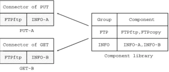
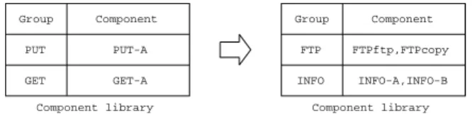
Moreover, in CBDL, we generate connectors from the UML diagrams. Note that the correctness of the connectors is guaranteed by the verification. In CBDL, by combining the connectors and components of a component library, we generate component-based software. The common software architecture of components istree architecture. There is a correspondence between AA-trees model of component specifications and tree architec- ture. Based on the correspondence, we generate the connectors. Because requirements of the target domain continue to change, the component library must continue to evolve.
We developed tree architectureto simplify the evolution of the component library.
The main ideas of CBDL using LFMB or LFME are as follows:
1. a formal definition of AA-trees model by using behavioral specifications or equational specifications,
2. the consistency verification methods,
3. a formal definition of tree architecture by using behavioral specifications, and 4. the connector generation methods, respectively.
The thesis is organized as follows.
In Chapter 2, we discuss preliminaries. Firstly, we discuss the Catalysis approach that is the base of CBDL. Secondly, we discuss algebraic specification. Projection-style behavioral specification used in LFMB and equational specification used in LFME are categories of algebraic specification. Then, we discuss abstract reduction system. Abstract reduction system, especially, term rewriting system is used for the verification of LFMB and LFME. After that, we discuss a specification language CafeOBJ. We use CafeOBJto specify projection-style behavioral specification and equational specification. Finally, we discuss JavaBeans and Servlets. The support tools of CBDL generate component-based software that is constructed from (1) JavaBeans or (2) JavaBeans and Servlets.
In Chapter 3, we discuss an overview of CBDL. CBDL is the component-based soft- ware development discussed in the thesis. Firstly, we discuss the process of CBDL and where formal methods apply to. Secondly, we discuss an overview of AA-trees model.
AA-trees model is a refinement of the model of objects and actions of the Catalysis ap- proach. In CBDL, we model business processes and behavior of components by using AA-trees model. Then, we discuss an overview of tree architecture. Tree architecture is the common software architecture of components in CBDL, which is used for avoiding architecture mismatch. After that, we discuss overviews of LFMB and LFME. LFMB and LFME are lightweight formal methods. In CBDL, we use LFMB and LFME for eliminat- ing inconsistencies in the UML diagrams. Finally, we discuss an overview of connector generation. Based on the correspondence between AA-trees model of components and tree architecture, the support tools of CBDL generate the connectors.
In Chapter 4, we discuss tree architecture. Firstly, we discuss what tree architecture is. Then, we discuss the correspondence between AA-trees model of components and tree architecture.
In Chapter 5, we discuss AA-trees model. Firstly, we discuss what AA-trees model is. Then, we discuss how to specify AA-trees model by using UML diagrams with OCL descriptions.
In Chapter 6, we discuss a verification method of equational specification with =.
Firstly, we discuss a complete deduction system of equational specification with=. Then, we discuss double term rewriting system with condition that is an implementation of the deduction system that uses term rewriting system.
In Chapter 7, we discuss LFMB. Firstly, we discuss projection-style behavioral specifi- cation. In LFMB, we use projection-style behavioral specification for formalizing AA-trees model. Secondly, we discuss how to formalize AA-trees model by using projection-style behavioral specification. Because AA-trees model is specified by using UML diagrams, then, we discuss how to translate UML diagrams into projection-style behavioral specifi- cation. Finally, we discuss how to verify consistency in the UML diagrams.
In Chapter 8, we discuss LFME. In LFME, we use equational specification for for- malizing AA-trees model. Firstly, we discuss how to formalize AA-trees model by using equational specification. Because AA-trees model is specified by using UML diagrams, then, we discuss how to translate UML diagrams into equational specification. Finally, we discuss how to verify consistency in the UML diagrams.
In Chapter 9, we discuss comparisons between LFMB and LFME. Because we formalize the same AA-trees model in LFMB and LFME, for the same verification about the model, the results of LFMB and LFME must be the same. The common verification of LFMB
and LFME is refinement verification. So, firstly, we discuss a correspondence between refinement verification in LFMB and that in LFME. Because the verification results of LFMB and LFME are the same, we predicted that the logic of projection-style behavioral specification was equational logic. The prediction is true. Then, we discuss that the logic of projection-style behavioral specification.
In Chapter 10, we discuss connector generation. Based on the correspondence between AA-trees model of components and tree architecture, the support tools of CBDL generate the connectors. Because tree architecture is a software architecture of an abstract level, to generate the connectors, there must be a correspondence between tree architecture and a software architecture of an implementation level. Firstly, we discuss a software architecture of an implementation level that uses JavaBeans. We call the software archi- tectureJavaBeans implementation of tree architecture. Then, we discuss how to generate the connectors of JavaBeans implementation of tree architecture. Finally, we discuss a software architecture of an implementation level that uses Servlets with JavaBeans. We call the software architectureServlets with JavaBeans implementation of tree architecture.
In Chapter 11, we discuss the support tools of CBDL. We developed two groups of support tools of CBDL. One is the group of the support tool of CBDL using LFMB. The other is the group of the support tools of CBDL using LFMB and LFME. Firstly, we discuss the support tool of the former group. Then, we discuss the support tools of the latter group.
In Chapter 12, we discuss case studies. We did case studies by using the support tools.
We did a case study of the domain of file transfer programs by using the support tool of CBDL using LFMB. Firstly, we discuss the case study. We did a case study of the domain of online bookstores by using the support tool of CBDL using LFMB and LFME. Then, we discuss the case study.
Finally, In Chapter 13, we discuss some conclusions.
Chapter 2
Preliminaries
2.1 The Catalysis Approach
The Catalysis approach[12] deals with all phases of CBD, which aremodeling phase,design phase, and implementation phase. LFMB and LFME deal with only the modeling phase andthe design phase. So, in this section, we summarize only those phases of the Catalysis approach.
In the modeling phase, we specify a business model of a target domain. In the design phase, we specify specifications of software that implements some parts of the business model.
An action of the Catalysis approach corresponds to a UML use case. An attribute is a function returning an object or a function returning a set of objects if its multiplicity is
“1” or “0. . . n”, respectively. Attributes are drawn by using two ways. One way is that an attribute is drawn in the middle part of a class box of a class diagram. Another way is that an attribute is drawn as a role of an association, which is a line drawn between class boxes. In the former case, multiplicity of the attribute is “1”. In the latter case, multiplicity is drawn near the attribute’s name. The effects of an action is described by changes between attributes’ values immediately before and after the action has happened.
Usually, the effects are specified by using OCL (the Catalysis extension). The most typical assertion for describing the effects is an equation whose form is
[object].[attribute] = F([object].[attribute]@pre)
where[object].[attribute]@preand [object].[attribute]are the attribute values immediately before and after the action has happened, respectively, andF is a function.
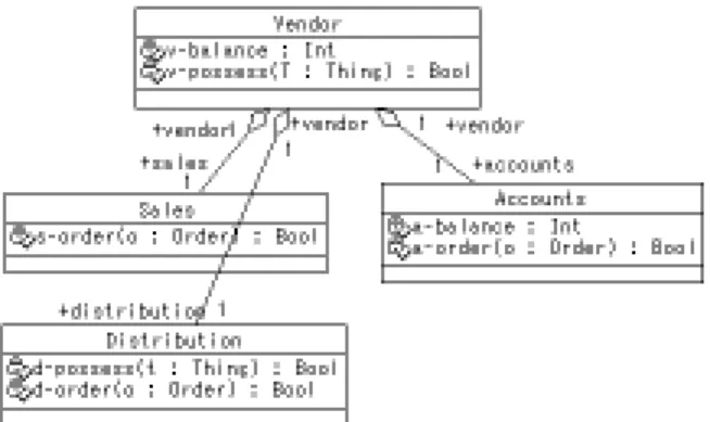
Example 1 Fig. 2.1 shows a usecase diagram. buy is an action. Purchaser and Vendor are objects, which participate in buy action. The effects of buy action are described by changes of values of those objects’ attributes. Fig. 2.2 shows a class diagram that spec- ifies attributes of the objects (classes). Attributes of a Purchaser object are p-balance, p-possess, and vendor. Attributes of a Vendor object are v-balance, v-possess, and pur- chaser. The multiplicity of p-balance, p-possess, v-balance, and v-possess is “1”. The multiplicity of vendor and purchaser is “0. . . n”. p-balance and v-balance are functions returning the balances of Purchaser and Vendor objects, respectively. p-possess and v- possessare functions returning the boolean values showing whether Purchaserand Vendor objects have a Thing object, respectively. price is a function returning the price of Thing.
Figure 2.1: An action and objects
Figure 2.2: Classes and their attributes
Figure 2.3: Decomposition of an object
buy action is an action that a Purchaser object buy aThing object from a Vendorobject.
buy action happens when the Purchaser object does not have the Thing object but the Vendor object has it. buy action cause payment for the Thing object and transportation of it. So, the precondition and the effects of buy action are specified by using OCL (the Catalysis extension) as follows:
action (P : Purchaser, V : Vendor)::buy(T : Thing) pre: (P.vendor(V) = true) and
(P.p-possess(T) = false) and (V.v-possess(T) = true)
post: (P.p-balance = P.p-balance@pre - T.price) and (P.p-possess(T) = true) and
(V.v-balance = V.v-balance@pre + T.price) and (V.v-possess(T) = false)
The “pre:” description is the description of the precondition. The “post:” description is the description of the effects. 2
There may be constraints on attributes’ values. We call such constraintsstatic invari- ants.
Example 2 Consider a Purchaser object and a Vendor object in Figure 2.2. There is a constraint that those objects can not have the same Thing object at the same time. The constraint is specified by using OCL (the Catalysis extension) as follows:
context (P : Purchaser, V : Vendor, T : Thing)
inv: (P.vendor(V) = true) and (P.p-possess(T) = true)
&
buy
makeorder/start buy notifyorder
pay deliver
/complete buy
Figure 2.4: Decomposition of an action
:Purch aser :Vendor
:Purch
aser :Sales :Distri bution
:Acco unts makeorder
notifyorder deliver
pay buy
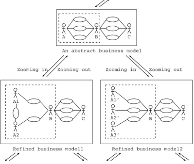
Zooming in Zooming out
Figure 2.5: Zooming in and out
=> (V.v-possess(T) = false)
inv: (V.purchaser(P) = true) and (V.v-possess(T) = true)
=> (P.p-possess(T) = false) 2
Objects and actions may be decomposed. For example, a Vendor object and buy action (Fig.2.1) are decomposed (Fig.2.3 and Fig.2.4). We call the process that actions and objects are decomposed Zooming in and the process that actions and objects are composed Zooming out(Fig.2.5).
There are the following differences between the modeling phase and the design phase.
• In the modeling phase, actions represent something that happens between a set of objects, but in the design phase, actions represent messages or methods and
• in the modeling phase, there is no system boundary, but in the design phase, there are system boundaries.
2.2 Algebraic Specification
For algebraic specification, we introduce the notations used later and refer to [14, 36] for a more detailed presentation. Algebraic behavioral specification has many formalisms, for example [5, 11, 15, 20, 27]. In this section, we discuss our formalism of algebraic behavioral specification, which is used for defining projection-style behavioral specification in Chapter 7.
2.2.1 Signature, algebra, and term
Signature
Definition 1 We letS∗ denote the set of all lists of elements from a set S, including the empty list which we denote []. 2
Definition 2 Given a set S of sorts, an S-sorted (or S-indexed) set A is a family {As| s ∈ S} of sets, one for each s ∈ S. We let |A| = ∪s∈SAs and we let a ∈ A mean that a∈ |A|. 2
Definition 3 Given a sort set S, then S-sorted signature Σ is an indexed family {Σw,s| w ∈ S∗, s ∈ S} of sets, whose elements are called operators, operation symbols, or function symbols. A symbol σ ∈Σw,s is said to have arity w, sort s, and rank w, s. In particular, any σ ∈ Σ[],s is called a constant symbol. We let |Σ| = ∪w,sΣw,s and we let Σ ⊆Σ mean that Σw,s⊆Σw,s for each w∈S∗ and s∈S. 2
Algebra
Definition 4 A Σ-algebra M consists of an S-sorted set also denoted M, i.e., a set Ms for each s∈S, plus
1. an element σM ∈ Ms for each σ ∈ Σ[],s, interpreting the constant symbol σ as an actual element, and
2. a function σM : Ms1 × · · · ×Msl → Ms for each σ ∈ Σw,s where w =s1· · ·sl for l >0, interpreting each operation symbol as an actual operation.
Together, these provide an interpretation ofΣinM. We may sometimes writeMσ instead of σM, and also Mw instead of Ms1× · · · ×Msl. The set Ms is called the carrier of M of sort s. 2
Using the above notation we can write:
Mσ :Mw →Ms. Term
Definition 5 Given an S-sorted signature Σ, then the S-sorted set TΣ of all Σ-terms is the smallest set of lists over the set |Σ| ∪ {(,)}(where ( and) are special symbols disjoint from Σ) such that
1. Σ[],s ⊆(TΣ)s for all s∈S, and
2. given σ∈Σs1···sl,s and ti ∈(TΣ)si for i= [1, . . . , l] thenσ(t1· · ·tl)∈TΣ,s. 2 Definition 6 Given a Σ-term t, subterms of t are defined as follows:
1. t is a subterm of t, and
2. if t=σ(t1· · ·tl) then subterms of ti are also subterms of t.
In particular, any subterm of t except t is called a proper subterm oft. 2 Term Algebra
Definition 7 We can view TΣ as a Σ-algebra as follows:
1. interpret σ ∈Σ[],s in TΣ as the singleton list σ, and
2. interpret σ ∈ Σs1···sl,s in TΣ as the operation which sends t1, . . . , tl to the list σ(t1· · ·tl), where ti ∈TΣ,si for i= [1, . . . , l].
Thus, TΣ is called the term algebra (over Σ). 2
2.2.2 Homomorphism, equation, and satisfaction
Homomorphism
Definition 8 An S-sorted arrow f : A → A between S-sorted sets A and B is an S- sorted family {fs | s ∈ S} of arrows fs : As → As. Given S-sorted arrows f : A → A and g :A → A, their composition g f is the S-sorted family {gs fs | s ∈S} of arrows.
Each S-sorted set A has an identity arrow, 1A={1As |s∈S}. 2
Definition 9 Given anS-sorted signatureΣandΣ-algebrasM andM, aΣ-homomorphism hm:M →M is an S-sorted arrow hm :M →M such that:
1. hms(σM) = σM for each constant symbol σ ∈Σ[],s and
2. hms(σM(e1, . . . , el)) = σM(hms1(e1), . . . , hmsl(el)) whenever l > 0, σ ∈ Σs1···sl,s, and ei ∈Msi for i= [1, . . . , l].
The composition hm2 hm1 : M → M of Σ-homomorphisms hm1 : M → M and hm2 : M →M is their composition as S-sorted arrows. 2
Equation
Definition 10 Σis a ground signature iff Σ[],s∩Σ[],s =∅ whenevers =s, andΣw,s =∅ unless w= [], i.e., iff it consists only of distinct constant symbols. 2
Definition 11 The union of two signatures is defined by:
(Σ∪Σ)w,s = Σw,s∪Σw,s.
A special case is union with a ground signature X. For this, we will use the notation:
Σ(X) = Σ∪X,
but only in the case |Σ| and |X| are disjoint. So, the above equation may be rewritten as:
Σ(X)[],s = Σ[],s∪Xs and
Σ(X)w,s = Σw,s when w= []. 2
Definition 12 A Σ-equation consists of a ground signature X of variable symbols (dis- joint from Σ) plus two Σ(X)-terms of the sort s ∈ S; we write such an equation in the form:
(∀X)t=t. 2
Definition 13 A conditional Σ-equation consists of a ground signature X disjoint from Σ, a set of pairs (ui, ui) (i= [1, . . . , k]) of Σ(X)-terms, and a pair (t, t) of Σ(X)-terms;
we write such a conditional equation in the form:
(∀X)t=t if ((u1 =u1) and · · · and (uk =uk)).
We call the part ((u1 =u1) and · · · and (uk=uk)) the condition part of the conditional Σ-equation and use C to denote the condition part. 2
Satisfaction
Lemma 1 Given a signature Σ, a ground signature X disjoint from Σ, a Σ-algebra M, and a map as : X → M, there is a unique Σ-homomorphism as : TΣ(X) → M which extends as, in the sense that ass(x) = ass(x) for each s ∈ S and x ∈ Xs. We call as an assignment from X to M. 2
We generally write as instead of as when there is no confusion.
Definition 14 A substitution of Σ-terms with variables in Y for variables in X is an assignment sb:X →TΣ(Y); we may use the notationsb:X →Y. The applicationof sb to t ∈ TΣ(X) is sb(t). Given substituting sb1 : X → TΣ(Y) and sb2 : Y → TΣ(Z), their composition sb2 sb1 (as substitutions) is the S-sorted arrow sb2 sb1 :X →TΣ(Z). 2 Definition 15 A Σ-algebra M satisfies a Σ-equation (∀X)t = t iff for any assignment as : X →M we have as(t) =as(t) in M. In this case we write:
M |=Σ (∀X)t=t. 2
Definition 16 A Σ-algebra M satisfies a conditional Σ-equation (∀X)t =t if C iff for any assignment as : X →M, if as(ui) =as(ui)for each(ui =ui)∈C, then as(t) =as(t) in M. In this case we write:
M |=Σ (∀X)t=t if C.
A Σ-algebra M satisfies a set E of conditional Σ-equations iff it satisfies each ceq ∈ E, and in this case we write:
M |=Σ E. 2
Lemma 2 Given a Σ-equation eq= (∀X)t =t, let ceq= (∀X)t=t if ∅. Then for each Σ-algebra M, M |=Σ eq iff M |=Σ ceq. 2
Consequently, we can regard any ordinary equation as a conditional equation with the empty condition, and we will feel free to do so hereafter. We generally omit the subscript Σ when there is no confusion.
2.2.3 Specification and model
Specification
Definition 17 An equational specification is a pair (Σ, E), consisting of a signature Σ and a set E of conditional Σ-equations. 2
Model
Definition 18 Given an equational specification(Σ, E), a(Σ, E)-modelM is aΣ-algebra such that:
M |=Σ E. 2
Definition 19 Given an equational specification (Σ, E), a conditional Σ equation ceq. If for each (Σ, E)-model M,
M |=Σ ceq,
in this case, we write:
E |=Σ ceq. 2
Term Model
Definition 20 Given aΣ-algebraM, aΣ-congruence relation onM is anS-sorted equiv- alence relation ≡={≡s| s ∈ S} on M, where each ≡s is an equivalence relation on Ms such that for each σ ∈Σs1···sl,s:
ei ≡si ei for i∈[1, . . . , l] implies σ(e1, . . . , el)≡s σ(e1, . . . , el) for ei, ei ∈Msi. 2
Lemma 3 Given a Σ-algebra M and a Σ-congruence ≡ on M, then the quotient of M by ≡, denoted M/ ≡, is also a Σ-algebra, in which σ ∈ Σ[],s is interpreted as [σ], and σ ∈Σs1···sl,s with l >0is interpreted as the map sending [e1], . . . ,[el]to [σ(e1, . . . , el)], for ei ∈Msi. 2
Corollary 4 Given an equational specification(Σ, E), the equivalence classes ofΣ-terms modulo E form a (Σ, E)-model, hereafter denoted TΣ,E. We call this (Σ, E)-model the term model (over (Σ, E)). 2
2.2.4 A complete deduction system of equational specification
Definition 21 Given an equational specification (Σ, E), the followingrules of deduction define the Σ-equations that are deducible (fromE):
1. (Assumption) Each Σ-equation in E is deducible.
2. (Reflexivity) Each equation of the form (∀X)t=t
is deducible.
3. (Symmetry) If (∀X)t=t
is deducible, then so is (∀X)t =t.
4. (Transitivity) If the equations (∀X)t=t, (∀X)t =t are deducible, then so is
(∀X)t=t.
5. (Congruence) If θ, θ : X →TΣ(Y) are substitutions such that for each x∈X, the equation
(∀Y)θ(x) = θ(x)
is deducible then given t ∈TΣ(X), the equation (∀Y)θ(t) =θ(t)
is also deducible.
6. (Substitutivity) If (∀X)t=t if C
is in E, and ifθ : X →TΣ(Y) is a substitution such that for each ui =ui ∈C, the equation
(∀X)θ(ui) =θ(ui) is deducible, then so is
(∀X)θ(t) = θ(t).
When an Σ-equation eq is deducible from E, we write:
E Σ eq. 2
Lemma 5 Given an equational specification (Σ, E) and a Σ-equation eq, then E |=Σ eq iff E Σ eq. 2
Lemma 6 Given an equational specification (Σ, E) and a conditional Σ-equation (∀X)t=t if C,
then
E |=Σ (∀X)t=t if C iff E∪C |=Σ(X) (∀∅)t =t. 2
2.2.5 Algebraic behavioral specification
Behavioral equation
Definition 22 A Σ-behavioral equation consists of a ground signature X of variable symbols (disjoint from Σ) plus two Σ(X)-terms of the sort s ∈ S; we write such an equation in the form:
(∀X)t∼t. 2
Algebraic behavioral specification
Definition 23 Let V and H be sets of sorts such that V ∩H =∅. Let Ψ be a V-sorted signature and Σ be a (V ∪H)-sorted signature such that Ψ ⊂ Σ. Let EΨ be a set of Ψ-equations andE be a set of Σ-equations and Σ-behavioral equations such that EΨ ⊂E.
We call a 4-tuple (V,Ψ, H,Σ) a hidden signatureiff it satisfies the following condition:
for each σ ∈Σw,s\Ψw,s, exactly one sort in H occurs in w.
We call a 6-tuple(V,Ψ, EΨ, H,Σ, E) an algebraic behavioral specificationiff it satisfies the following conditions: (1) (V,Ψ, H,Σ) is a hidden signature and (2) for each eq ∈ E\EΨ, at least one operator in Σ\Ψ occurs in eq.
For the algebraic behavioral specification (V,Ψ, EΨ, H,Σ, E), we call sorts in V visible sorts, sorts in H hidden sorts, and (Ψ, EΨ) a data specification. 2
A visible sort and a hidden sort correspond to a data type and the set of states of a black box, respectively.
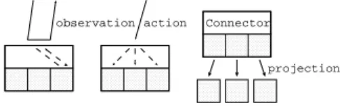
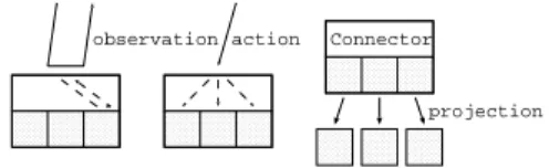
States of the black box are only observed by using the following observable contexts.
Note that observations are for observing states of the black box and actions are for chang- ing states of it.
Definition 24 Let (V,Ψ, H,Σ) be a hidden signature. We call σ ∈ Σw,s\Ψw,s an obser- vation ifs∈V. We callσ ∈Σw,s\Ψw,s an actionifs ∈H andscoincides with the hidden sort occurring in w. 2
Definition 25 Let (V,Ψ, EΨ, H,Σ, E) be an algebraic behavioral specification. Let h be a hidden sort. Let v and vi be visible sorts. Let xi be a variable of sort vi such that xi = xj if i = j. Let be a special h-sorted variable called hole. The set AllOch of observable contexts of sort h is inductively defined as follows: (1) for each observation obs : v1· · ·vk h → v and for each variable xis, obs(x1, . . . , xk,) ∈ AllOch and (2) for each action act : v1· · ·vk h → h, for each element oc of AllOch, and for each xis, oc[act(x1, . . . , xk,)] ∈ AllOch where oc[t] denotes the term obtained by substituting the term t for . 2
Satisfaction
Definition 26 Let (V,Ψ, EΨ, H,Σ, E) be an algebraic behavioral specification and M be a Σ-algebra. M satisfies a Σ-behavioral equation (∀X)t ∼ t iff for any assignment as : X →M, for any observable context oc, we have as(oc[t]) =as(oc[t]) in M. In this case we write:
M |=Σ (∀X)t∼t. 2
Definition 27 Let (V,Ψ, EΨ, H,Σ, E) be an algebraic behavioral specification and M be a Σ-algebra. M satisfies E iff it satisfies each eq∈E and in this case we write:
M |=Σ E. 2
Definition 28 Let (V,Ψ, EΨ, H,Σ, E) be an algebraic behavioral specification and M be a Σ-algebra. We call M a hidden (V,Ψ, EΨ, H,Σ, E)-algebra iff M |=Σ E. 2
Definition 29 Let (V,Ψ, EΨ, H,Σ, E) be an algebraic behavioral specification and eq be anΣ-equation orΣ-behavioral equation. When M |=Σ eq holds for each hidden(V,Ψ, EΨ, H,Σ, E)-algebra M, we write:
E |=Σ eq. 2
2.3 Abstract Reduction System
We introduce the notations used later and refer to [1] for a more detailed presentation.
2.3.1 Abstract reduction system
Definition 30 An abstract reduction system (ARS) is a structure A = (A,(→α)α∈I) consisting a set A and a sequence of binary relations →α on A, also called reduction or rewrite relations. In the case of just one reduction relation, we also use→ without more.
If for a, b∈A we have (a, b) ∈→α, we write a→α b and call b a one-step (α-) reduct of a. 2
Definition 31 The transitive reflective closure of →α is written as →∗α. So a →∗α b if there is a possible empty, finite sequence of reduction stepsa=a0 →α a1 →α · · · →α an = b. The element b is called an (α-) reduct of a. The transitive closure of →α is→+α. The converse relation of →α is ←α. The union →α ∪ →β is denoted by →αβ. 2
Definition 32 Let A = (A,(→)) be an ARS, → is confluent if ∀a, b, c ∈ A . ∃d ∈ A . (c←∗ a →∗ b⇒c→∗ d←∗ b). 2
Definition 33 Let A = (A,(→)) be an ARS, → is terminating if every reduction se- quence a0 →a1 → · · · eventually must terminate. 2
Definition 34 We say that a∈A is a normal formif there is no b∈A such that a →b.
Further, b ∈ A has a normal form if b →∗ a for some normal form a ∈ A. We call a a normal form of b. 2
2.3.2 Term rewriting system
Definition 35 Given t ∈ TΣ(X), the set of variables in t, denoted var(t) it the least ground signature Y ⊆X such that t∈TΣ(Y). 2
Notice thattis a ground term iffvar(t) = 0. From now on, we will often just say “Σ-term”
for what we were previously careful to call a “Σ-term with variables”.
Definition 36 Given a signature Σ, a conditional Σ-rewrite rule is a conditional Σ- equation (∀X)t1 = t2 if C such that var(t2) ⊆ var(t1) = X, and var(u) ⊆ var(t1) and var(v) ⊆ var(t1) for each pair u, v ∈ C. It follows that we can use the notation t1 →t2 if C, which is unambiguous because X is determined by t1. A Σ-term rewriting system (Σ-TRS) is a set of conditional Σ-rewrite rules; we may omit the prefixΣ when it is not needed, and we may denote such a system by (Σ, E). 2
Definition 37 Given a Σ-term rewriting system (Σ, E), the one-step rewriting relation is defined for Σ-terms t, t as follows:
t⇒t iff there exists: a rule (∀X)t1 →t2 if C in E; a Σ-term t0 ∈TΣ({z} ∪Y)having exactly one occurrence of the variable z; and a substitutionsb:X →TΣ(Y) such that:
sb(u) =sb(v) for each pair u, v ∈C, t=t0(z ←sb(t1)) and t =t0(z ←sb(t2)).
In the case, the pair t0, sb is called a match to t by the rule t1 → t2 if C. The term rewriting relationis the transitive reflexive closure of one-step rewriting relation, for which we write t⇒∗ t and say that t rewrites to t (under (Σ, E)). 2
2.4 CafeOBJ
In the thesis, we use a specification languageCafeOBJ[10] because it supports behavioral specifications. The specification of natural numbers with successor and plus by CafeOBJ is as follows:
mod! NAT { [ Nat ]
op 0 : -> Nat op s_ : Nat -> Nat op _+_ : Nat Nat -> Nat
vars N1 N2 : Nat eq N1 + 0 = N1 .
eq N1 + s N2 = s(N1 + N2) . }
In CafeOBJ, specifications are divided into modules which are declared bymod!ormod*.
Natwhich is surrounded by [and ]is a (visible) sortwhich denotes a data type. op, eq, and vardeclare an operator, an equation, and a variable, respectively. For op, we call a list of sorts which occur between :and ->an arityand a sort which occurs in the right of -> a sort (of the operator). For example, consider 0 operator. Its arity is∅ and its sort is Nat. A signature Σ and a set of axiomsE are the parts which are constructed fromopand eq of a specification, respectively. We use (Σ, E) to denote an equational specification.
We call a set with functions which correspond to operators of Σ an Σ-algebra. We call a symbol sequence of operators, “,”, “(” and “)”, like “0”, “s(0)”, and “0 +s(s(x))”a term.
We call terms which do not have variables closed terms. We call the Σ-algebra whose set is constructed from closed terms the term Σ-algebra. We use TΣ to denote this term Σ-algebra. We call the quotient of the term Σ-algebra by E the quotient term Σ-algebra.
We use TΣ,E to denote this Σ-algebra. ! of mod! declares that the model of this module is its quotient term Σ-algebra. On the other hand,* ofmod* declares that the models of this module are all Σ-algebras which satisfy the equations of E.
2.5 JavaBeans and Servlets
2.5.1 JavaBeans
JavaBeans 1 are components programmed by using Java, which have the following inter- faces:
1. events used for reporting change of the states of JavaBeans, 2. propertiesused for observing the states, and
3. methodsused for calling inner functions of JavaBeans.
2.5.2 Servlets
Servlets are components programmed by using Java, which are used on Web servers.
1Java and all Java-based trademarks and logos are trademarks or registered trademarks of Sun Mi- crosystems, Inc. in the United States and other countries.
Chapter 3
An Overview of CBDL
We developed lightweight formal methods called LFMB (a Lightweight Formal Method using Behavioral specification)andLFME (a Lightweight Formal Method using Equational specification). CBDLis a Component-Based software Development approach using LFMB or LFME.
CBDL is based on the Catalysis approach[12]. In the Catalysis approach, the software development process is divided into modeling phase, design phase, and implementation phase. For modeling phase and design phase, CBDL is a refinement of the Catalysis approach. But, for implementation phase, CBDL is an original approach.
By using the Catalysis approach, we get the benefit of formal methods thatwe can get clear understanding of a target software in the process of specifying the target software.
But, because the verification is out of the scope of the Catalysis approach, we can not get the benefit that we can verify properties of the target software using the verification systems by only using the Catalysis approach.
In modeling phase and design phase of the Catalysis approach, UML diagrams are specified by a number of software engineers. So, there may be inconsistencies in the UML diagrams. To eliminate the inconsistencies, consistency verification is useful. Because most of software engineers are non-specialists of the verification, the verification should be executed automatically as far as possible. So, we developed lightweight formal methods complimenting the Catalysis approach called LFMB and LFME.
In LFMB and LFME, we use AA-trees model as a model of objects and actions.
Because the Catalysis approach is not conscious of the verification, its model may not have sufficient information about the verification. AA-trees model is a refinement of the model that the specifiers are forced to specify the information.
We developed a software architecture for component-based software tree architecture.
We developed it to simplify the evolution of the component library. In implementation phase of CBDL, we use tree architecture as the common software architecture of compo- nents.
In design phase of CBDL, we model components whose architecture is tree architecture by using AA-trees model.
Moreover, in CBDL, we generate connectors from the UML diagrams. Note that the correctness of the connectors is guaranteed by the verification. In CBDL, by combining the connectors and components of a component library, we generate component-based software. The common software architecture of components istree architecture. There is a correspondence between AA-trees model of component specifications and tree architec-