Japan Advanced Institute of Science and Technology
JAIST Repository
https://dspace.jaist.ac.jp/
Title The tool that support highly reliable component-based software development
Author(s) Matsumoto, Michihiro; Futatsugi, Kokichi
Citation
Research report (School of Information Science, Japan Advanced Institute of Science and
Technology), IS-RR-2000-018: 1-8
Issue Date 2000-06-22
Type Technical Report
Text version publisher
URL http://hdl.handle.net/10119/8388
Rights
Description リサーチレポート(北陸先端科学技術大学院大学情報
The Tool that supports
Highly Reliable
Component-Based
Software
Development
Michihiro Matsumoto ft and Kokichi Futatsugi t
June 22, 2000
IS-RR-2000-18
f Graduate School of Information Science,
Japan Advanced Institute of Science and Technology
$ NCS Division, PFU Limited.
(C) M. Matsumoto and K. Futatsugi, 2000
The Tool that supports Highly Reliable Development
Component-Based Software
Michihiro Matsumoto* and Kokichi Futatsugi Graduate School of Information Science, Japan Advanced Institute of Science and Technology 1-1 Asahidai, Tatsunokuchi, Ishikawa 923-1292, JAPAN
{
mit
ihiro,
koki
chi
}
@
j aist .ac.
j p
Abstract
We discuss the support tool for highly reliable component-based software development. The advan-tages of the tool are automated refinement verification and automated connector generation. As software ar-chitecture of component-based software, we select tree architecture, in which components are represented by projection-style behavioral specification. The input of the tool is (a) a requirement specification of target soft-ware, (b) a refined specification specifying how to com-bine components, and (c) the components. (a) and (b) are projection-style behavioral specifications. (c) is JavaBeans. The output of the tool is JavaBeans that is given by combining (c) and connectors. The tool as-sures high reliability of the output by verifying refine-ment and generates the connectors of (c).
1. Introduction
Component-based software development has gained in popularity. In the development, firstly by selecting components from a component library, and then by combining them, component-based software is devel-oped. Many software engineers use component tech-nologies, for example, JavaBeans, COM, EJB, and CORBA. The reason for the popularity is that it can increase software productivity.
In this paper, we discuss the support tool for highly reliable component-based software development. The
*On leave from NCS Division , PFU Limited.
PFU Limited developed this tool in cooperation with JAIST. This project was supported in part by grant Support program for young software researchers 99-004 from Information-technology Promotion Agency and Research Institute of Software Engineer-ing. The first author was the project leader of this project.
advantages of the support tool are automated refine-ment verification and automated connector generation.
To increase software productivity, components must be reused. But components cannot be combined with components which have different software architecture, because there is the architectural mismatch problem
[6] . So, to reuse components, we must select software architecture.
In component-based software development, we deal not with software but a software family. One of the most promising software architectures for a software family is product line architecture [1, 4, 14, 16], whose idea at least dates back to [15]. In this paper, as soft-ware architecture, we select one kind of product line
architecture called tree architecture [13].
Recently, even component-based enterprise systems have been developed. So, the importance of the tech-nology how to develop highly reliable component-based software has increased. Component-based software is constructed from components that provide basic func-tionality and connectors that combine components. Because components are reused again and again, the costs of reliability are recovered from the software fam-ily that may use the components. But because connec-tors are not reused, t the costs of reliability must be recovered from the software that use the connectors. So, the costs of reliability should be low.
In tree architecture, a requirement specification of target software and a refined specification specifying how to combine components can be represented by projection-style behavioral specification [8, 11, 12, 13] . Refinement verification is the verification whether the refined specification satisfies the requirement specifica-tion. We assure high reliability of target software by tThe reusability of connectors depends on software architec-ture. For layered architecture [1, 4, 14, 16], there are some works [14, 16] about reusable connectors. About a comparison between layered architecture and tree architecture, see Section 6.
observationll
/action
Component Figure 1. A componentI/observation/action
\.~ / 1 \projectionFigure 2. A composite component
verifying refinement. We developed the method how to automate refinement verification of projection-style be-havioral specification. Also, we developed the method how to automate connector generation from a given re-fined specification. In the support tool, we implement these methods. By using the support tool, we can re-duce the costs of reliability of the connectors.
In [13], we discussed the software development method that the support tool can support if compo-nents are JavaBeans compocompo-nents and its theoretical foundation. So, contributions of this paper are Sub-section 2.3, Section 3, Section 4, and Section 5.
The input of the support tool is (a) a requirement specification of target software, (b) a refined specifica-tion specifying how to combine components, and (c) the components. (a) and (b) are projection-style be-havioral specifications. (c) is JavaBeans. The output of the support tool is JavaBeans that is given by com-bining (c) and connectors. The support tool assures high reliability of the output by verifying refinement and generates the connectors of (c).
2. Tree architecture
In this paper, we select tree architecture [13] as soft-ware architecture of component-based softsoft-ware. For tree architecture and the relationship between tree architecture and projection-style behavioral specifica-tion, see [13] in detail.
2.1. Tree architecture
In tree architecture, we fix a target software fam-ily [15] and prepare a component library that is
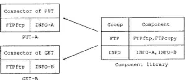
Connector of PUT FTPftp INFO-A PUT-A Connector of GET FTPftp INFO-8 GET-B Group FTP INFC Component FTPftp,FTPcopy INFO-A,INFO-B Component library
Figure 3. A software family and a component li-brary
divided by behavior of the components. Component-based software is developed by firstly selecting compo-nents from the component library, and then by combin-ing them. So, tree architecture is one kind of product line architecture [1, 4, 14, 16].
In tree architecture, a component (Fig. 1) is an object such that:
1. it has a state,
2. it has two kinds of operations observations used for observing the state and actions used for
changing the state,
3. information about the state is only gotten by using observations, and
4. the state is only changed by using actions.
We can regard an object constructed from some com-ponents as a component, too. We call an object satisfy-ing the followsatisfy-ing conditions a composite component
(Fig. 2):
1. for each observation of it, there exists a
ing component and a corresponding observation of the constructing component,
2. for each action of it, for each constructing ponent, there exists a corresponding action of the
constructing component or all action of the
structing component do not correspond to the
tion, and
3. for each constructing component, there exists a projection from the state of it to the state of the constructing component.
We call the part of a composite component that com-bines constructing components connector.
Example 1 Consider a software family of file transfer programs (Fig. 3). The software family includes PUT-A that transfers PUT-A's files on the local machine to a re-mote machine and GET-B that transfers B's files on a remote machine to the local machine. The component library is divided into FTP group that transfers files and INFO group that manages personal information, like user names and passwords. FTPftp and FTPcopy provide file transfer functions using FTP protocol and using copy command of OS, respectively. FTPftp and FTPcopy belong to FTP group. A and INFO-B provide management functions of A's personal in-formation and B's personal inin-formation, respectively. INFO-A and INFO-B belong to INFO group. PUT-A is constructed from FTPftp, INFO-A, and the connector of PUT. GET-B is constructed from FTPftp, INFO-B, and the connector of GET.
2.2. Tree architecture and projection-style
behavioral specification
Pro jection-style behavioral specifications can be used for specifying behavior of components of tree ar-chitecture and specifying how to combine components to make composite components. Projection-style be-havioral specification is constructed from component specification used for specifying behavior of compo-nents and connector specification used for specifying how to combine components to make composite compo-nents. For the formal definitions related to projection-style behavioral specification, see [8, 11, 12, 13] . In this paper, projection-style behavioral specifications are written by using specification language CafeOBJ . For CafeOBJ , see [5] in detail.
2.2.1 Component specification
In component specifications, we specify the effects of actions on states through observations by using equa-tions.
Example 2 Consider PUT of Example 1. nent specification of PUT group component A is as follows: mod* bop bop bop bop bop var var eq PUT { getremote isinlocal isinremote setremote put P : Put M : Machine isinlocal(I pr (BO OL The compo-, like *[ Put ]* Put -> Machine
File Put -> Bool
File Machine Put -> Bool Machine Put -> Put File Put -> Put vars I J : File
put(J, P))=isinlocal(I, P) .
ceq isinremote(I, M, put(J, P)) = t
if (I == J) and (getremote(P) == M) . [ The remained codes are omitted. ]
In CafeOBJ , bop, var(s), and (c)eq declare obser-vations and actions, variables, and (conditional) equa-tions, respectively. Put surrounded by *[ and ] * is a hidden sort (type), that is the set of PUT group compo-nent's states. getremote, isinlocal, and isinremote are observations used for getting the current target re-mote machine's name, observing whether the specified file is in the local machine, and observing the speci-fied file is in the specispeci-fied remote machine, respectively.
setremote and put are actions used for setting target remote machine and transferring the specified file to the target remote machine. The first equation specifies the effect of put on states through isinlocal, i.e. put does not add or does not delete files on the local machine. The second equation specifies the effect of put on states through isinremote, i.e. put transfers the specified file to the target remote machine.
2.2.2 Connector specification
In connector specifications, we specify correspondences between observations and actions of a composite com-ponent and those of constructing components.
Example 3 Consider PUT of Example 1. The con-nector specification of PUT group component that spec-ifies how to combine FTP group component and INFO group component is as follows:
mod* bop bop bop bop bop op op eq eq PUT { pr(BOOL+MACHINE+FILE) pr (FTP getremote isinlocal isinremote setremote put ftp info getremote (P) ]* Put -> Machine File Put -> Bool File Machine Put -> Machine Put -> Put File Put -> Put Put -> Ftp Put -> Info = getmachine(info(P)) Bool ')) _ ~tmachine (info (P)) , name(getmachine(info(P))), passwd(getmachine(info(P))), ftp (P)) . eq info(put(I, P)) = info(P) . [ The remained codes are omitted. ]
pr(FTP+INFO) declares that component specifica-tions of FTP group component and INFO group com-ponent are imported. ftp and info are projections
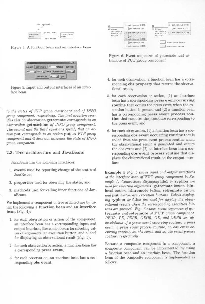
obs property press event 8unction?' bean obs event Interface bean
Figure 4. A function bean and an interface bean
Figure 5. Input and output interfaces of an inter-face bean
to the states of FTP group component and of INFO group component, respectively. The first equation spec-ifies that an observation getremote corresponds to an observation getmachine of INFO group component. The second and the third equations specify that an ac-tion put corresponds to an acac-tion put on FTP group component and it does not influence the state of INFO group component.
2.3. Tree architecture and JavaBeans
JavaBeans has the following interfaces:
1. events used for reporting change of the states of JavaBeans,
2. properties used for observing the states, and 3. methods used for calling inner functions of
aBeans.
We implement a component of tree architecture by us-ing the followus-ing a function bean and an interface bean (Fig. 4):
1. for each observation or action of the component,
an interface bean has a corresponding input and output interface, like comboboxes for selecting
ues of arguments, an execution button, and a label
for displaying an observational result (Fig. 5), 2. for each observation or action, a function bean has
a corresponding press event,
3. for each observation, an interface bean has a responding obs event,
Press getremote execution Button (1)getremote PEOR !getremote PE al getremote (3:)getremote PEPR. OEOR getremote OE (4)getremote OEPR Press setremote execution Button (1)setremote PEOR setremote PE f2:):aetsemotec.:.P15PR : ---1 Interface beans nFunction beans
Figure 6. Event sequences of getremote and se-tremote of PUT group component
4. for each observation, a function bean has a sponding obs property that returns the
tional result,
5. for each observation or action, (1) an interface
bean has a corresponding press event occurring
routine that occurs the press event when the ecution button is pressed and (2) a function bean
has a corresponding press event process
tine that executes the procedure corresponding to
the press event, and
6. for each observation, (1) a function bean has a responding obs event occurring routine that is
called from the press event process routine when
the observational result is generated and occurs
the obs event and (2) an interface bean has a
responding obs event process routine that
plays the observational result on the output
face.
Example 4 Fig. 5 shows input and output interfaces of the interface bean of PUT group component in Ex-ample 1. Comboboxes displaying fuel or syphon are used for selecting arguments. getremote button, isin-local button, isinremote button, setremote button, and put button are execution buttons. Labels display-ing syphon or false are used for display the obser-vational results when the corresponding execution but-tons are pressed. Fig. 6 shows event sequences of ge-tremote and setremote of PUT group component. PEOR, PE, PEPR, OEOR, OE, and OEPR are ab-breviations of a press event occurring routine, a press event, a press event process routine, an obs event oc-curring routine, an obs event, and an obs event process routine, respectively.
Because a composite component is a component, a composite component can be implemented by using a function bean and an interface bean. The function bean of the composite component is implemented as follows:
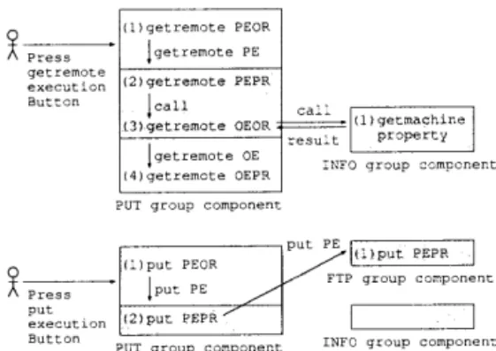
Press getremote execution Button (1)getremote PEOR lgetremote PE (2)getremote PEPR ~call (.31getremote OEOR getremote OE (4)getremote OEPR call
PUT group component result
(1)getmachine property INFO group component
Press put execution Button (1)put PEOR !put PE (2)put PEPR put PE
PUT group component
(1)put PEPR group component INFO group component
Figure 7. Event sequences of getremote and put of PUT composite component
1. for each observation, the obs property returns the value of the corresponding obs property of the
structing component,
2. for each observation, the obs event occurring tine occurs the obs event with the value of the
responding obs property of the constructing
ponent, and
3. for each action, for each constructing component,
the press event occurring routine occurs the sponding press event if it exists and as the result
of the occurrence, the corresponding press event
process routine starts.
Note that these correspondences are described in the connector specification.
Example 5 Fig. 7 shows event sequences of ge-tremote and put of PUT composite component in Example 3.
3. Automated refinement verification
The verification for assuring high reliability of component-based software is refinement verification. We prepare (1) a component specification specified re-quirements of target software and (2) a connector spec-ification specified how to combine components to make the target software. Refinement verification is the
ver-ification whether all equations of the component spec-ification is deduced from equations of the connector specification.
For behavioral specification [2, 7], there is no deduc-tion system that can deduce any equadeduc-tion of any behav-ioral specification [3] . But, projection-style behavioral specification, a special class of behavioral specification,
has a good property Property 1 [13]. The support tool automates refinement verification by using Property 1. We call symbol sequences constructed from opera-tors, variables, "(" , ")" , and "," terms. We can regard equations as rewrite rules from the left hand sides to the right hand sides. We call systems that calcu-late terms by applying rewrite rules (equations) term rewriting systems (TRSs) [9]. Consider a term. We call a term that is gotten by applying rewrite rules zero or some times to the term and cannot be applied any more a normal form of the term.
Property 1 Given a component specification and a connector specification of the target software. And given a (conditional) equation ceq of the component specification. Moreover, given an appropriate set of cases about conditions of constructing components' states. Let E be a TRS constructed from the equations of the connector specification, equations that represent a case, and the equation between the normal forms of the both sides of conditions of ceq. Calculate normal foi-rras of the both sides of the main part of ceq by us-ing E for each case. Then, ceq holds in the connector specification if and only if the normal forms are equal for each case.
In our research, moreover, we found the procedure that finds an appropriate set of cases.
For CafeOBJ , there is a CafeOBJ verification system [5] which executes calculations of TRSs. The CafeOBJ verification system has a script language that can de-scribe adding equations and has a command comparing the normal forms of both sides of an equation. The sup-port tool automates refinement verification by generat-ing a verification script based on Property 1 and the above procedure, and by executing it on the CafeOBJ verification system.
Example 6 The verification script for verifying whether the second (conditional) equation of the compo-nent specification in Example 2 holds in the connector specification in Example 3 is as follows:
open . eq I = J .
eq getmachine(info(P)) = M .
red isinremote(I, M, put(J, P)) == t . close
getmachine(info(P)) is a normal form of ge-tremote(P). red command compares the normal forms of the both sides, like isinremote(I, M, put(J, P)) and t. For this example, case analysis is
I I7:::I---I t Connector action \ observation (p ent)\(obs property) ev I---I I I Function beans of Constructing components A requirement specification (CafeOBJ) A refined specification (CafeOBJ)
1\
I / I I The support tool jTarget --Isoftware :(JavaBeans) j Components (JavaBeans)Figure 8. The structure of the connector imple-mentation
Figure 9. Input and output of the support tool
4. Automated connector generation
As we discussed in Subsection 2.3, a component of tree architecture is constructed from a function bean and an interface bean. Especially, a composite compo-nent is constructed from these JavaBeans. As we dis-cussed in Subsection 2.3, the function bean of the com-posite component can be implemented by using only information described in the connector specification.
But to implement the interface bean, some informa-tion is necessary. The input and output interface needs information about what input interfaces for setting ar-guments are necessary and what an output interface for displaying the observational result is necessary. The obs event process routine needs information about how to display the observational result.
The support tool prepares default interfaces and a default obs event process routine. For setting argu-ments, textfields are used. For displaying the obser-vational result, a label is used. The default obs event process routine display the observational result on the label.
The connector corresponds to the function bean and the interface bean of the composite component (Fig. 8). The support tool automatically generates the con-nector, i.e. these beans by using information described in the connector specification, default interfaces, and a default routine.
As an optional function, the support tool supports a function that selects an input and output interface and an obs event process routine. In fact, the input interfaces of Fig. 5 are comboboxes selected by using this function.
5. The support tool
The input of the tool is (a) a requirement speci-fication of target software, (b) a refined specispeci-fication specifying how to combine components, and (c) the
components (Fig. 9). (a) and (b) are projection-style
Refr.nement verzfier Connector generator Interface generator Software generator
Figure 10. The structure of the support tool
behavioral specifications described by using CafeOBJ . (c) is JavaBeans. The output of the tool is JavaBeans that is given by combining (c) and connectors (Fig. 9). The tool assures high reliability of the output by veri-fying refinement and generates the connectors of (c).
5.1. The structure of the support tool
The support tool is constructed from refinement ver-ifier, connector generator, interface generator, and soft-ware generator (Fig. 10).
Refinement verifier generates verification scripts, like the script in Example 6 by using Property 1 and then, sends those scripts to CafeOBJ verification sys-tem and gets the results.
Connector generator generates the function bean of the composite component by using the method dis-cussed in Section 4.
Interface generator generates the interface bean of the composite component by using the method dis-cussed in Section 4.
Software generator generates the target software by combining (1) the function bean and the interface bean of the composite component and (2) the function beans of the constructing components.
5.2. The manipulations of the support tool
Fig. 11 is an outlook of the support tool. When the support tool starts, the textarea shows parameters of the support tool, like TmpDir and SpecDir (Fig. 11).
TmpDir directory is the directory in which Jav-aBeans are stored. So, in TmpDir directory, compo-nents of the component library are stored. Moreover,
III
I.'-i4dsa.- :9. 0 .40 [ `€ is :ci l+
jig. r: D: Yte4Ylest SeecDi r: D: Hti se19991,e>mYOUt CaruePoa: C:YcoewM.coe 1ServerAdd: sypm.i ai et The server is run ins.
Figure 11. An outlook of the support tool
the output of the support tool is stored in TmpDir di-rectory.
SpecDir directory is the directory in which CafeOBJ specifications are stored. So, component specifications and connector specifications are selected from these CafeOBJ specifications.
When Add Spec button is pressed, a dialog is dis-played. By using this dialog, component specifications and connector specifications are selected.
When Verify button is pressed, the refinement ifier executes refinement verification. If refinement ver-ification fails, the textarea shows unsatisfied equations.
The support tool supports manual refinement ver-ification. When the textarea shows unsatisfied equa-tions, Add Spec button is changed to Eq Verify button. Writing a verification script for an unsatis-fied equation on the textarea and then pressing Eq Verify button, the refinement verifier executes verifi-cation whether this script succeed. By iterating this process for all equations, we can execute manual re-finement verification. By using this manual rere-finement verification, we found the idea of Property 1.
Constructing components of composite components may be composite components. This means compos-ite components may have hierarchical structures. The support tool supports stepwise refinement to deal with the hierarchical structures. A component specification imported to a connector specification may have a corre-sponding connector specification. The process of step-wise refinement is as follows: In a stage, the former connector specification is input by using Add Spec button and then by pressing Verify button, refinement verification is executed. In the next stage, the latter connector specification is input by using Add Spec button and then by pressing Verify button, refinement verification between the component specification and the latter connector specification is executed.
When Add Comp button is pressed, a dialog is displayed. By using this dialog, the correspondences between (1) the component specifications input by
us-CarBody Manual Gasoline Category CarBody Transmission Engine Components CarBody Automatic,Manual Gasoline,Electric Figure 12. Component library Layered architecture
ing the dialog of Add Spec button and (2) components in the component library are input. The software gen-erator uses these correspondences.
When Gene Comp button is pressed, the connec-tor generaconnec-tor and the interface generaconnec-tor generate the function beans and the interface beans, respectively.
When Gene App button is pressed, the software generator generates the target software.
If Chg Data Comp button is pressed before Gene Comp button is pressed, a dialog is displayed. By using this dialog, other input and output interfaces and other obs event process routines are selected as we discussed in Section 4.
6. Related work
One of the most popular product line architecture is layered architecture [1, 4, 14, 16] .
In layered architecture, component categories corre-sponding to component specifications can be arranged into a hierarchy of layers, where each layer represents a category and the categories that most other categories depend on are moved the bottom of the hierarchy (Fig.
12).
The components of each layer other than the bottom layer called connectors. But, components and connec-tors of layered architecture correspond to components of tree architecture. Note that the combination types
are fixed in layered architecture, but those are not fixed in tree architecture. In tree architecture, selecting a connector is selecting a combination type.
Connectors of layered architecture are represented by parameterized specification. The advantage of parameterized specification is that it can represent reusable connectors, because it can represent patterns [14] .
For connector generation, in layered architecture, generative programming is proposed [4]. But, it does not verify refinement.
7. Future work
Our goal is to produce (a) a component-based soft-ware development methodology that uses formal
IUML editor UML spec / OafeOBJ translator \UML spec Domain analyzer
CafeOBj spec ++contents1/feedback ;Changing
The support tool in this paper
Component library component
Figure 13. The support tool of the methodology
ods without users consciousness and (b) a support tool of the methodology. So, one direction of future work is developing the methodology and the support tool of the methodology. We assume that users can use UML, which is one of the most popular modeling lan-guage. In our plan, the support tool is constructed from (a) UML editor used for specifying software of target software family, (b) CafeOBJ translator used for translating UML specifications to projection-style behavioral specifications, (c) domain analyzer used for domain analysis, (d) component library, and (e) the support tool in this paper (Fig. 13).
Another area of future work is making component libraries for some domains.
8. Conclusion
We have studied verification methods of behavioral specification [8, 10, 11, 12, 13] . In this paper, we dis-cussed the application of the verification methods to component-based software development.
In this paper, we discussed the support tool for highly reliable component-based software development. The advantages of the support tool are automated re-finement verification and automated connector gener-ation. By using the support tool, we can reduce the costs of reliability of the connectors.
Our goal is to produce (1) a component-based soft-ware development methodology that uses formal meth-ods without users consciousness and (2) a support tool of the methodology. The support tool automates re-finement verification and connector generation. So, this work is one step towards the goal.
References
[1] D. Batory and S. O'Malley. The design and
tation of hierarchical software systems with reusable components. ACM Transaction on Software
ing and Methodology, 1(4):355-398, 1992.
[2] M. Bidoit and R. Hennicker. Behavioural theories and the proof of behavioural properties. Theoretical
puter Science, 165:3-55, 1996.
[3] S. Buss and G. Rosu. Incompleteness of behavioral
logics. In Proceedings of the Third Workshop on gebraic Methods in Computer Science (CMCS'2000),
volume 33 of Electronic Notes in Theoretical Computer Science. Elsevier Science, 2000.
[4] K. Czarnecki and U. W. Eisenecker. Components and generative programming (in ESEC/FSE'99). Software
Engineering Notes, 24(6):2-19, 1999.
[5] R. Diaconescu and K. Futatsugi. CafeOBJ Report. AMAST Series in Computing 6. World Scientific,
1998.
[6] D. Garlan, R. Allen, and J. Ockerbloom.
tural mismatch: Why reuse is so hard. IEEE Software,
12(6):17-26, 1994.
[7] J. A. Goguen and G. Malcolm. A hidden agenda. nical Report CS97-538, UCSD Technical Report, 1997. [8] S. Iida, M. Matsumoto, R. Diaconescu, K.
sugi, and D. Lucanu. Concurrent object
tion in CafeOBJ. Technical Report IS-RR-98-0009S,
Japan Advanced Institute of Science and Technology
(JAIST), 1998.
[9] J. Kiop. Term rewriting systems. In Background:
Computational Structures, volume 2 of Handbook of Logic in Computer Science, pages 1-116. Oxford ence Publications, 1992.
[10] M. Matsumoto and K. Futatsugi. Test set tion — toward automated verification of behavioural
properties . In Proceedings of Second International
Workshop on Rewriting Logic and It's applications,
volume 15 of Electronic Notes in Theoretical Computer
Science. Elsevier Science, 1998.
[11] M. Matsumoto and K. Futatsugi. Object composition
and refinement by using non-observable projection erators: A case study of the automated teller machine
system. In OBJ/CafeOBJ/Maude at Formal Methods
'99, pages 133-157. THETA, 1999.
[12] M. Matsumoto and K. Futatsugi. Simply observable
behavioral specification. In Proceedings of Asia-Pacific
Software Engineering Conference'99, pages 460-467. IEEE, 1999.
[13] M. Matsumoto and K. Futatsugi. High-reliable
component-based software development by using gebraic behavioral specification. In Proceedings of
Third International Conference on Formal
ing Methods. IEEE, to appear.
[14] M. Mezini and K. Lieberherr. Adaptive plug-and-play
components for evolutionary software development (in OOPSLA'98). ACM SIGPLAN Notices,
116, 1998.
[15] D. L. Parnas. On the design and development of gram families. IEEE Transactions on software
neering, 2(1):1-9, 1976.
[16] Y. Smaragdakis and D. Batory. Implementing layered designs with mixin layers. In European Conference
on Object-Oriented Programming'98, number 1445 in LNCS, pages 550-570. Springer-Verlag, 1998.