Japan Advanced Institute of Science and Technology
JAIST Repository
https://dspace.jaist.ac.jp/Title RFID-based mobile robot guidance to a stationary target
Author(s) Kim, Myungsik; Chong, Nak Young Citation Mechatronics, 17(4-5): 217-229
Issue Date 2007
Type Journal Article
Text version author
URL http://hdl.handle.net/10119/7874
Rights
NOTICE: This is the author's version of a work accepted for publication by Elsevier. Myungsik Kim, Nak Young Chong, Mechatronics, 17(4-5), 2007, 217-229,
http://dx.doi.org/10.1016/j.mechatronics.2007.01. 005
RFID-based Mobile Robot Guidance to a Stationary Target
Abstract
Retrieving accurate location information about an object in real-time, as well as any general information pertinent to the object, is a key to enabling a robot to perform a task in cluttered, dynamically changing environment. In this paper, we address a novel technique for the guidance of mobile robots to help them identify, locate, and approach a target in our daily environments. To this end, we propose a standard for the use of radio-frequency identification (RFID) systems and develop a prototype that can be easily installed in existing mobile robots.
Specifically, when an RF signal is transmitted from an RF transponder, the proposed RFID system reads the transponder-encoded data and simultaneously picks up the direction of the transponder using the received signal strength pattern. Based on the angle of signal arrival, we develop the guidance strategies that enable a robot to find its way to the transponder position. Moreover, to cope with multi-path reflection and unexpected distortions of the signals resulted from environmental effects, we present several algorithms for reconstructing the signals. We demonstrate that an off-the-self mobile robot equipped with the proposed system locates and approaches a stationary target object. Experimental results show that the accuracy of the proposed system operating at a frequency of 315 MHz falls within a reasonable range in our normal office environment.
I. Introduction
While considerable progress has been made in robots in the last few decades, most of them still have difficulties in recognition of dynamically changing environments such as our daily environments. Every day, new products are manufactured and brought into our daily life, which requires robots to expand their knowledge accordingly to handle the new objects. With the limited functionalities of the current sensors, however, facilitating robot recognition is quite
challenging in the real world. Thus, one of the most important issues in robotics today is how we can make robots develop the competence for the given task autonomously recognizing their environment correctly and efficiently.
Recent approaches to facilitating robot recognition are structuring the environment and connecting the robot digitally with its environment through wireless communication systems. This enables the robot to understand and adapt to changes in the environment without any additional efforts, as the information about the environment can be directly transmitted to the robot [1-3]. To build such an environment, a consistent communication interface should be developed. Recently, RFID gains increasing attention, since the radio frequency signal can eliminates the need for an optical line of sight and transmits a relatively large amount of information [4][5]. Thus we can use the RFID tag as an information terminal and embed it into every object in the environment. Then robots read out the tag-encoded data that points to the database using the RFID reader, whereby detailed information about the object can be downloaded from the networked knowledge base. Thus robots can integrate new information seamlessly into their existing knowledge. Despite all the promise surrounding RFID, it is still not possible to locate an RFID tag. We need to develop this extra function for sensing the spatial information is needed to the current RFID-based interface to build environmental map and execute tasks in the environment [6-8].
Over the years, for the localization problem in indoor environments, various RF-based techniques have been developed [9]. One of the well tried methods was using the known locations of reference stations, where the transponder position was reported by nearby stations [10], [11]. However, this approach had the problem of cost and space with the number of stations and the interval between the stations affected the accuracy. Likewise, the signal strength based distance estimation was often used with the stations, but the accuracy deteriorated due to the scattering and reflecting of transmitting signal [12-17]. Another method uses the difference of arrival time between the RF signal and the ultrasonic pulse [18-20]. However, such systems require pre-organization of location of sensors or beacons, thus the setup and running cost might
limit their applicability in a large scale space. Also, the optical line of sight is needed for transmitting the ultrasonic pulse.
To deal with the problem of object localization in a real and practical way, we should consider the system’s ease of use and range of applicability. Hence the system employs simple RF transponders and their reader without additional sensors and/or reference stations. In this paper, as a first step toward RF-based localization, we propose a simple, low-cost location sensing system incorporating 315 MHz active RFID devices. This system is expected to enable the robot to efficiently gather information and understand the context of the environment using the RFID transponder’s location as well as stored information.
Specifically, the reader senses the object location by analyzing the received signal strength pattern with bearings of its loop antenna. To cope with a signal distortions resulted from environment effects, we present signal reconstructing algorithms that help estimate the angle of arrival correctly. With this system, we make a commercial mobile robot find its way to a stationary RFID transponder.
The following section briefly addresses the fundamental electromagnetic theories required to find directions of arrival of RF signals. Section III introduces the design of the prototype system. Details of direction finding results are provided in Section IV. Several localization modes are proposed and evaluated in Section V. Finally, conclusions are drawn in Section VI.
II. Direction Finding
A. Omni-directional antennaThe location of an object can be specified in a two-dimensional polar coordinate system with two coordinates: the distance of the object from the origin and the direction (or the angle) of the object from the polar semi-axis. Even if both coordinates are not available simultaneously, we can estimate the location by triangulation with either the distance or the direction of the object. Generally, RFID systems use an omni-directional antenna such as a whip antenna, thus the
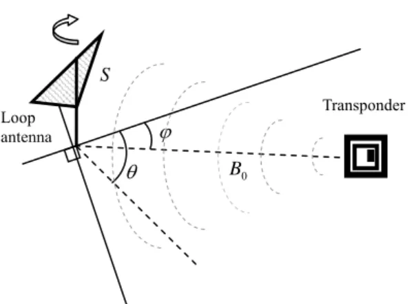
Fig. 1 Geometry of the localization : Plane wave and antenna rotation
Transponder θ ϕ 0 B Loop antenna S
location estimate resorts to the distance based triangulation. The distance from the signal source can be determined by measuring the strength of the received signal or the time of flight of the signal [4].
The signal strength is inversely proportional to the distance in the far-field, and the sum of the cubic of the distance and
the square of distance in the near-field, respectively. Thus the distance of the transponder can be calculated from the signal strength and the transponder position is estimated using triangulation technique. However, since the accuracy deteriorates due to surface scattering and reflecting of transmitting signal, this method is hard to use in an obstacles-cluttered environment. Another way is to calculate the distance of the transponder using the time interval of transmitting signal and back-scattering signal. But it is difficult to detect the time difference correctly, since the time of the RF signal flies in several meters is very small in the order of pico-seconds. To cope with the above-mentioned problems of the omni-directional antenna used in current RFID systems, we investigate the directional antenna.
B. Directional antenna
With the directional antenna such as a loop antenna, the arrival direction of the RF signal can be determined, as the strength of the received signal changes according to the angle between the antenna plane and the transmitted wave plane as shown in Fig. 1. If an electromagnetic wave is transmitted to a loop antenna, a voltage V is induced in the antenna coil given as
) sin(
0
θ
−ϕ
∝CSB
V , (1)
where S is the surface area of the antenna,
B
0 the magnetic flux density of the transmitted signal passing through the antenna,θ
the rotation angle of the antenna,ϕ
the direction of the transponder, and C the environmental effect constant [21-24]. The pattern of the inducedvoltage level with the rotation of a loop antenna is ideally the Arabic numeral eight in polar coordinates then we can estimate the direction of the transponder using the maximum or the minimum value of the received signal strength. The location of the transponder can be determined by two methods using the antenna bearings to the transponder. One is using the signal strength. As the distance can be determined using the detected signal strength, the position of the transponder can be determined with the direction and the distance. Since the signal strength of the directional antenna changes according to the antenna bearings, the distance should be calculated using the maximum signal strength of the received signal pattern. However, the accuracy of the distance estimated from the signal strength is not high in real environments. The other method is the triangulation technique. After sensing the direction to transponder at two different positions, the location of transponder can be calculated by two bearings and the interval between two sensing positions.
III. Prototype Development
A. Experimental Set-upIn order to verify the feasibility of RF-based localization, we have developed a prototype 315 MHz RFID reader for location awareness. The diagram and the photo of developed location
Pan/Tilt Head
Signal Strength Detector
Data Analyzer
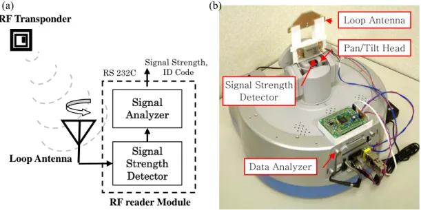
Fig. 2 Experiment system (a) Diagram of the system (b) Photo of the system RF Transponder Signal Strength Detector Signal Analyzer Signal Strength, ID Code RS 232C RF reader Module Loop Antenna (a) (b) Loop Antenna
sensing system are shown in Fig. 2. The system consists in an electrically small loop antenna and its reader. When an RF signal is transmitted from an RF transponder, the signal received by the loop antenna mounted to the pan and tilt unit is fed to the RF reader module. A signal strength detector in the module converts the RF signal to the DC voltage and transmits it to a signal analyzer then the signal analyzer generates the digitalized signal strength and the identification (ID) code encoded in the transponder. The generated signal strength and ID code together with the antenna facing direction is provided to the application target through a serial communication interface. Then the direction of the transponder signal with an ID code is determined using the signal strength pattern through rotating the antenna facing angle.
B. Antenna
The loop antenna is designed in the following way. i. Choose an antenna type that is highly directional.
ii. Using the electromagnetic simulation software “ACCUFIELD” developed by Fujitsu limited for electromagnetic compatibility analysis, a number of loop antennas with various shapes and shielding patterns are tested.
iii. Considering the characteristics such as resonant frequency, impedance, gain, and radiation pattern, the shape of the antenna is optimized.
iv. Prototype and manufacture the antenna, and measure its specific characteristics. v. Match the impedance of the antenna and
tune for a specific frequency.
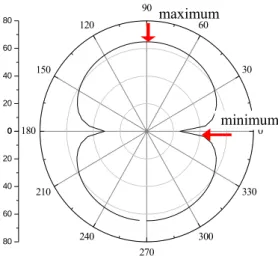
Fig. 3 shows the simulation result of the radiation pattern of the antenna design in polar coordinates scaled in dBμV/m. The pattern has apparently two minimum and two maximum levels that display the same characteristics as the signal receiving pattern of the directional
0 20 40 60 80 0 30 60 90 120 150 180 210 240 270 300 330 0 20 40 60 80
Fig. 3 Radiation pattern of the antenna design maximum
Front
32 mm
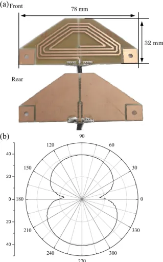
Fig. 4 Antenna prototype: (a) Loop antenna (b) Signal receiving pattern of the antenna (b) 78 mm Rear (a) 0 20 40 0 30 60 90 120 150 180 210 240 270 300 330 0 20 40 antenna.
Fig. 4-(a) shows the developed loop antenna manufactured by printed circuit board etching, having a width of 78 mm and a height of 32 mm. The rear side is shielded and perpendicularly opened to improve the sensitivity of signal strength sensing about the horizontal plane. The signal receiving pattern of the antenna according to the antenna rotation angle is shown in Fig. 4-(b). The transponder is set at the direction of zero degrees and the pattern is measured in an electromagnetic dark room. The pattern also has apparently two dominant minimum and maximum levels that can be used to satisfy the
direction finding requirement. If we find the antenna rotation angle at which the voltage level is minimized or maximized, we can estimate the direction of the transponder. Comparing to the maximum level, the minimum level is more evident and less affected by environmental conditions. Thus, we can find the direction of the RF signal with good accuracy using the minimum level [25].
C. Signal Strength Detector
Fig. 5 shows the 315 MHz RF signal strength detector resided inside the RF reader module. The schematic of the detector is shown in Fig. 5-(a). When an RF signal in the range of -120 dBm to -45 dBm is transmitted to the antenna, the signal is filtered and fed to the power detector, which is then converted and amplified to a DC voltage ranging from 0 to 5 volts.
Fig. 5 Signal strength detector:
(a) Schematic of the detector (b) Picture of the detector (c) Input-output characteristic of the detector (b) V Out antenna 24 mm 5V In GND -140 -120 -100 -80 -60 -40 -20 0 1 2 3 4 5 V Out (DCV) Input (-dBm) (c) 54 mm Filter RF power detector antenna Amplifier Weak RF signal (a)
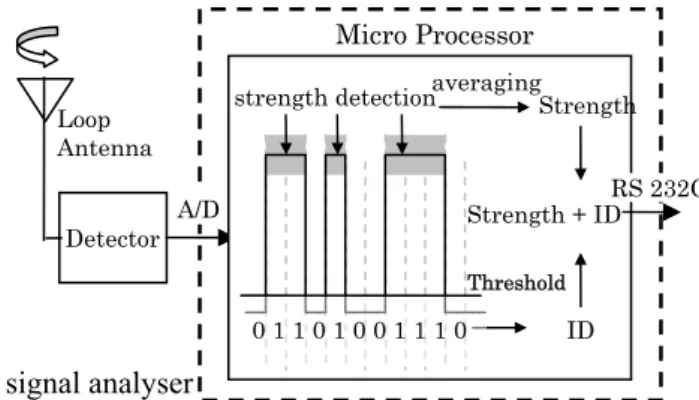
Fig. 6 The structure of signal analyser
Detector Loop Antenna
strength detection averagingStrength
ID Strength + ID 0 1 1 0 1 0 0 1 1 1 0 Threshold RS 232C Micro Processor A/D signal analyser
Fig. 5-(b) shows the picture of the detector that has a width of 54 mm and a height of 24 mm. The input and output ports include the RX input from the antenna, the 5 DC volt input from the robot USB port, and the DC output fed to the signal analyzer. Fig 5-(c) shows the input-output characteristics, where the input signal within the range of -115 dBm to -45 dBm is converted linearly to the DC voltage.
D. Signal Analyzer
Fig. 6 shows the block diagram of the signal analyzer developed using a micro processor. When an RF signal is transmitted from a transponder, the
induced signal at the antenna is transmitted to the RF reader module and the signal strength detector in the module converts the signal to a DC voltage pulse, which is sent to an A/D converter of the microprocessor. The signal from the transponder used in this experiment is modulated by On-Off Keying (OOK) and the DC voltage pulse from the signal strength detector has the same rectangular shape. Thus, the microprocessor counts ons (1’s) and offs (0’s) and adds the signal strength when the digitalized pulse
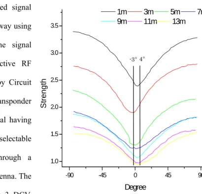
-90 -45 0 45 90 1.0 1.5 2.0 2.5 3.0 3.5 St re ngt h Degree 1m 3m 5m 7m 9m 11m 13m
Fig. 7 Received strength patterns according to the distance between antenna and transponder
-3° 4°
signal is higher than the threshold,whereby the ID code and average strength of the signal is obtained. Then the signal analyzer sends an ordered set of ID and strength level to the robot via the RS-232C interface. However, since the offset level of the voltage is easily varied by the system conditions, the threshold is dynamically adjusted by monitoring the minimum level of the transmitted pulse. Automating the above processes, the transponder direction can easily be determined with an antenna scanning in the horizontal plane [26].
IV. Direction Sensing Result of the System
A. Direction sensing using the prototypeFig. 7 shows the received signal pattern measured in the hallway using the developed system. The signal source is a 315 MHz active RF transponder manufactured by Circuit Design, Inc.. The transponder continuously sends RF signal having a uniform interval with four selectable twenty byte ID codes through a quarter wavelength whip antenna. The mode of operation requires 3 DCV. Note that the direction toward which
the antenna plane faces the transponder is 0 degree. The strength level become minimal when the antenna faces the transponder, and is reduced, the distance increases.
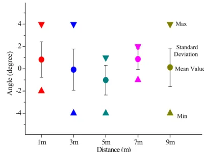
Fig. 8 shows the statistical results about the estimated direction according to the transponder distance. Directions were measured 50 times from the various distances with respect to the transponder at zero degrees. The figure indicates that the average directions measured from all
Fig. 8 Direction sensing error ranges of the developed system according to the distance
1m 3m 5m 7m 9m -4 -2 0 2 4 A ng le ( deg ree) Distance (m) Mean Value Max Min Standard Deviation
Fig. 9 RF signal distorted by the obstacle.
Chair
-100 -50 0 50 100
1.0 1.5 2.0
Without Obstacle With Chair
Sign al Stre ng th (DC V ) Angle (Degree) Mobile Robot Transponder (a) (b) the distances are within the
range of ± 1 degree with a maximum of ± 4 degree errors. This accuracy can approximate the transponder position that will remain within 7 percent of the distance between the communicating pairs of the transponder and the reader.
We have thus established a reasonable assurance of accuracy as we expected for various indoor applications.
However, many uncertain factors can exist and contaminate the original signal in real environments. It is therefore very difficult to find the correct direction if we simply attempt to find the minimum strength level in the distorted strength pattern. We present several algorithms to precisely determine the direction to the
transponder in the following subsection. B. Signal reconstruction algorithm
In a real environment, RF signals are easily distorted by the environmental effect such as reflection, refraction, and scattering by obstacles. Also, the white noise of the system affects the received signal pattern substantially. Fig. 9 shows the distorted signal pattern by the environmental effect. When a metallic chair is positioned between the robot antenna and the
transponder as shown in Fig. 9-(a), the propagation path of the transponder signal may be disturbed. In Fig. 9-(b), the solid line is the signal pattern without the chair and the dashed line is the distorted pattern by the chair. The signal strength was lowered and abruptly dropped when the chair exists.
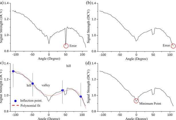
Fig. 10 illustrates the proposed scheme to sequentially reconstruct the distorted patterns. Fig. 10-(a) shows the distorted signal pattern. The adjacent averaging in Fig. 10-(b) eliminates the unexpected peak by replacing the data with the new value by averaging neighboring values around each data point. But the signal pattern is not very symmetrical. As one half is too small comparing another half, the detected minimum level is still incorrect. The minimum level should be found for the data bounded by the inflection points. If we designate the inflection points over the received pattern, whereby the pattern can be divided into a valley and two hills, we can find the minimum point in the valley range. Since the signal form should be an absolute sine function, we can employ a 4-th order polynomial fitted to the data points as shown in Fig.
-100 -50 0 50 100 0.8 1.0 1.2 1.4 Sign al Strength (DCV) Angle (Degree) -100 -50 0 50 100 0.8 1.0 1.2 1.4 Sign al S tre ngth (DCV) Angle (Degree) -100 -50 0 50 100 0.8 1.0 1.2 1.4 Sign al Strength (DCV) Angle (Degree) -100 -50 0 50 100 0.8 1.0 1.2 1.4 Signal S treng th (DC V ) Angle (Degree) valley hill hill Error Error Minimum Point Polynomial fit (a)
Fig. 10 Algorithms for reconstructing distorted signal: (a) Distorted signal (b) Adjacent averaging (c) Polynomial fitting (d) Determine minimum level
Inflection point.
(c) (d)
10-(c). Then two local maxima and one minimum can be found with the inflection points from the dashed fitting line. We can finally determine the minimum strength level and its corresponding antenna angle between the two inner inflection points from the actual signal pattern as shown in Fig. 10-(d). Thus, the direction to the transponder can be estimated correctly, even though the direction sensing RFID system is exposed to the environmental effect and the white noise [27].
We believe that this fairly constant level of accuracy of the direction sensing enables to reliably determine the position of the transponder in indoor environments. The direction-based localization of the transponder will be discussed in the following section.
V. Localization Schemes
We test the location sensing accuracy of the proposed RFID system using a mobile robot. The developed directional antenna is attached to the pan and tilt head of the robot that acquires the strength of the signal according to the panning angle of the antenna, as well as the transponder identification data. Three different methods are proposed in this work.
A. Navigation through a minimum level direction
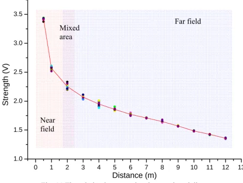
The location of the transponder can be determined with two parameters: the direction of the transponder and the distance in the direction calculated by the signal strength. The relationship between the distance and the signal strength measured by the developed system is shown in Fig. 11. The strength was measured 10 times at each position. Dots indicate the maximum strength of the signal in the logarithm scale and the red line fits their average value. It is shown that the strength is reduced rapidly in the near field range, and linearly in the far field range. Therefore the distance to the transponder can be roughly calculated from the signal strength
V
max as⎩
⎨
⎧
+
×
+
×
=
2 max 2 1 max 1C
V
A
C
V
A
d
b , (2)order to fit the slope in the near field. We set b as 2 for simplifying the equation.
However, the distance is apt to be overestimated due to the scattering and the reflection of the signal in real environments. As the loss and gain of the strength is varied by the environmental condition, we usually estimate the strength of the arrival signal using the path loss and attenuation table [28]. For example, in the general office environment, it is known that the error in strength estimation will not exceed about 20 %. Note that this just gives a rule of thumb for estimating, and if there exist partitions with metallic frame, the error definitely increases. The robot thus needs to measure the signal strength intermittently while moving an estimated distance until the pre-specified strength is detected. Note that, the curve rises rapidly in the near field zone while the robot comes close to the transponder position. Thus we can calculate the distance with enough high accuracy. If the strength passes beyond the pre-specified level, the robot stops moving, since it has approached within close proximity to its target.
Fig. 11 The relation between signal strength and distance
0 1 2 3 4 5 6 7 8 9 10 11 12 13 1.0 1.5 2.0 2.5 3.0 3.5 Str e n g th (V ) Distance (m) Near field Far field Mixed area
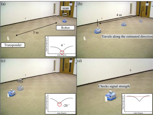
Fig. 12 shows the results of the robot navigation following the direction of the minimum strength. The inserted box shows the pattern of the signal strength measured at respective positions. In Fig. 12-(a), the direction of the minimum strength was 4 degrees and the maximum signal strength was relatively weak. In Fig. 12-(b), the robot then rotated 4 degrees clockwise and headed in that direction and traveled 4 m that has a margin of 1 m from the calculated distance in Eq. (2). The robot repeated scanning the environment after it traveled 4 m so that it could compensate for the errors in the direction sensing as well as the distance calculation. In Fig. 12-(c), the robot modified its heading angle and traveled along the new direction. Finally in Fig. 12-(d), when the maximum signal strength was above the terminating threshold, the red dotted line in the inserted box, the robot approached the transponder within 50 cm of its target.
Fig. 13 shows the localization results with various transponder distances after calibrating the constants
A
and C, and the terminating threshold strength. Since the shape of the distance toFig. 12 Transponder localization using navigation: (a) scans the transponder direction and determines the distance (b) travels the distance (c) scans and travels again (d) checks the strength
level and terminates travel Transponder Robot 5 m (b) (a) scan 4 m Si gn al S tr e n g th ( D C V ) Angle (Degree) 4 ˚ (c) (d)
Checks signal strength
Si gn al Str e ng th (D CV ) Angle (Degree) -20 ˚ Si gn al St re n g th ( D CV) Angle (Degree) Travels along the estimated direction
strength curve changes as the sensing range changes from the near field to the far field, the constants
A
and C was determined by measuring the signal strength at different positions.However, the transmitted signal is easily affected by the environment effect including humidity and time as well as the system condition. Thus, it is impossible to acquire the correct calibration constant that can be used to determine the exact distance to the transponder.
Using the navigation method, the robot moves directly toward the transponder and corrects the direction and the distance when it terminates the current travel. As this method simultaneously uses the direction and the distance, it is expected to be fast and used in a long narrow space. However, it is difficult for the ordinary user to use this method highly dependent on the field calibration.
B. Bearing-based Triangulation
Another approach is the triangulation method using the antenna bearings to the transponder
-0.5 0.0 0.5 0 1 2 3 4 5 6 -0.5 0.0 0.5 -0.5 0.0 0.5 -0.5 0.0 0.5 -0.5 0.0 0.5 -1.5-1.0-0.5 0.0 0.5 1.0 1.5
Y Pt (m)
X Pt (m) X Pt (m) X Pt (m) X Pt (m)
X Pt (m)
X Pt (m)
(a) (b) (c) (e) Start pt. Tag pt.Fig. 13 The localization result using navigation with correct calibration factor (a) 1 m, (b) 2 m, (c) 3 m, (d) 4 m, (e) 5 m, (f) 6 m
l 1
θ θ 2
d
Fig. 14 The scheme of triangulation technique
Transponder Robot Heading 1 θt s θ Robot Heading 2
Fig. 15 Triangulation with errors in antenna bearing
Transponder (0,0) (0,yo) Position 1 Position 2 l t θ ϕ γ Line 1 Line 2 1 θ θ 2 Robot Heading 1 Robot Heading 2 x y
measured at two different positions as shown in Fig. 14. When an electromagnetic signal is transmitted from a transponder, the robot can determine the direction of the transponder θ1 at the current position. The robot then turns θt clockwise or counterclockwise after aligning the heading in the transponder direction and moves to
another position to determine the direction of the transponder θ2 at that position. The turning angle θt and the moving interval l can arbitrarily be decided. Then the distance d from the robot to the transponder can be calculated as
⎟⎟ ⎠ ⎞ ⎜⎜ ⎝ ⎛ + = t s s l d θ θ θ tan sin cos , (3)
where θs is the acute angle of intersection between the transponder direction θ2 and the robot heading direction calculated as θs=π−θ2.
However, the directional antenna prototype includes the direction sensing error as shown in Fig. 8. It is also noted that the transponder localization accuracy depends on the turning angle
t
determine the turning angle and the interval distance that yield a low localization error, we simulate how the direction sensing error affects the localization error. In the right-handed Cartesian coordinate system of Fig. 15, the direction sensing system is located at (0, 0), denoted in the figure as Position 1, and the transponder (0, yo). The robot finds the direction of the
transponder at this position with an error of ϕ . Assume that the interval distance can be written as l= pyo, where p is the constant relating the estimated distance of the transponder and the interval. Thus, the second measurement position is
[
−pyosin(θt +ϕ), pyocos(θt +ϕ)]
. (4) Note that θ and ϕ are negative values, because those are turned clockwise from the y-axis. t Thus the coordinates in Eq. (4) indicate Position 2 in the figure. If we draw Line 1 from Position 1 to the transponder with the direction sensing error ϕ , the equation of the line can be written asy
x=−tanϕ . (5)
Similarly, Line 2 from Position 2 extending to the transponder direction with the sensing error γ can be written as ) cos( ) cos( ) tan( γ α ϕ θ γ α γ α + − − + + + = t o py x y , (6) where ⎭ ⎬ ⎫ ⎩ ⎨ ⎧ + + − = − ) sin( ) cos( 1 tan 1 ϕ θ ϕ θ α t t p p .
Then, we can determine the location of the transponder as the intersection point between Line 1 and Line 2 at the following coordinates.
⎟⎟ ⎠ ⎞ ⎜⎜ ⎝ ⎛ − + − − + − + − − + − , ) cos( ) cos( cos , ) cos( ) cos( sin ϕ γ α ϕ θ γ α ϕ ϕ γ α ϕ θ γ α ϕ t o t o py py . (7)
Fig. 16 shows the triangulation results of the transponder located at (0, 1) calculated by Eq. 7 with respect to the interval constant and the turning angle. Considering the accuracy of the prototype, the direction sensing error was assumed to lie within the range of ±4 degrees with a Gaussian distribution. The results are plotted within the range of interest, from -0.35 to 0.35 in x-axis and from
0.65 to 1.35 in y-axis.
The expected error is considered satisfactorily small with the interval constant 1 and the turning angle 15 degrees in the figure. However, it is sometimes difficult to have an enough interval distance in spatially constrained real environments, where obstacles may exist. Also, the transponder distance tends to be overestimated by the environmental effect. Therefore the smaller values of the interval constant might be more appropriate for the real environment. When the interval constant is less than 1, the error becomes small with a 45 degree turning angle. We therefore determined that the turning angle is kept at 45 degrees and the interval constant remains less than 1 in this work.
Fig. 17 shows how the robot localizes a transponder using the triangulation method with Fig.16 Location sensing accuracy with respect to interval constants and angles.
P = 0.2 P = 0. 35 P = 0. 5 P = 0. 75 t θ = 15° t θ = 30° t θ = 45° t θ = 60° t θ = 75° t θ = 90° P = 1 P = 1. 5
selected parameters. The signal strength pattern measured at each position is also shown. In Fig. 17-(a), the robot scans the environment and finds the direction of the minimum level to be 0 degree as expected, since the transponder is located in front of the robot. The robot turns 45 degrees clockwise and moves to the next position in Fig. 17-(b). The moving interval is determined by the maximum level of the signal strength. At the second position, the robot turns 45 degrees counterclockwise and scans again in Fig. 17-(c). Then the robot determines the transponder position using the two bearings measured at each position and the interval between them. Finally, the robot turns 45 degrees counterclockwise and approaches the transponder.
Fig. 18 shows the localization results as the transponder position changes. The black circles show the initial robot position and the transponder position, the small dots indicate the second measurement point and the final robot positions and the lines are the paths of the robot, and the large gray circle is the 50 cm boundary from the transponder position. At the start position, robot measures the direction of the transponder, and turns 45 degrees clockwise to move to the
Fig. 17 Transponder localization using triangulation (a) Scan the transponder direction (b) turns and moves to another position (c) scan again (d) determines transponder position
2 m (b) (a) S igna l St re ng th ( D CV ) Angle (Degree) 0 ˚
turn and move 1 m scan Transponder Robot (c) (d) Si gn al St re ng th (DCV) Angle (Degree) -45 ˚ scan
turn and move 1 m
next position. The interval distance constant selected is 0.5. The robot determines the direction at the second position and calculates the distance to the transponder.
When the robot moves toward the transponder located less than 3 m away, it can arrive within the 50 cm circle from the transponder as shown in Fig. 18-(a), (b), (c), and (d). As the distance increases, the localization error increases as shown in Fig. 18-(e), which is resulted from the direction sensing error.Also, if the distance of the transponder increases, the interval distance increases as well. Therefore the triangulation is not suitable to localize a transponder located a long distance away in a narrow space.
c. Hybrid
To cope with the problems of both the navigation method and the triangulation method, we simultaneously employ those two methods. As we mentioned before, the triangulation method would not be suitable for a long distance and the navigation method can not be used without proper calibration. Even though it is difficult to find the exact position by the navigation method, the robot can move toward the transponder. If the signal strength becomes beyond the pre-determined strength threshold, the robot finds the transponder position using the triangulation method. Fig. 19 illustrates the basic idea of the hybrid method, where the robot
(a) (b) (c) (e)
Fig. 18 The localization result using triangulation (a) 1 m, (b) 1.5 m, (c) 2 m, (d) 2.5 m, (e) 3 m (d) -0.5 0.0 0.5 0.0 0.5 1.0 1.5 2.0 2.5 3.0 3.5 -0.5 0.0 0.5 -0.5 0.0 0.5 -0.5 0.0 0.5 1.0 -0.5 0.0 0.5 1.0 Y Pt (m) X Pt (m) X Pt (m) X Pt (m) X Pt (m) X Pt (m)
navigates toward the transponder in the minimum strength direction and triangulates the transponder position when the robot approaches within a boundary. The boundary was selected as 2 m considering the accuracies that the current triangulation and strength-based distance estimation methods can offer.
It is shown in Fig. 20 that the robot approaches its docking target. Note that the moving interval was different in Fig. 20-(a) and (b),
because we used two different sets of terminating threshold level and C in Eq. (2). The robot thus may not reach the position of the transponder or may overrun passing the transponder if only the navigation method is employed. However, using the triangulation as well as the navigation, the robot could approach within 30 cm from the transponder in both cases. Start pt. Tag pt. boundary -1 0 1 0 1 2 3 4 5 6 -1 0 1 0 1 2 3 4 5 6 Y Pt (m) X Pt (m) X Pt (m) (b)
Fig. 20 The hybrid method with different terminating values and Cs (a)
Fig. 18 The hybrid method:
navigation is followed by triangulation within 2m boundary
Transponder Robot 6 m scan Si gn al S tr engt h (DCV) Angle (Degree) 3 ˚ boundary turn and move
S ig n al S tr e ng th ( D C V ) Angle (Degree) 2 m boundary -15 ˚
turn and move scan and determine the position
Si gnal St rengt h ( D C V ) Angle (Degree) - 42 ˚ Start pt. Tag pt. Navigation Triangulation
V. Conclusion
The RFID system for location awareness is a very promising and challenging research issue. In this paper, we proposed a cost-effective location sensing RFID system for mobile robot object location tracking in indoor environments. The prototype RFID system that consisted of a loop antenna, a signal strength detector, and a signal analyzing unit, determined the location of the RFID transponder analyzing the strength pattern of received signals with rotating the antenna. The antenna was attached onto the pan head of the mobile robot. Because the signal can be distorted in the real environment, three algorithms were presented to reconstruct the distorted signal and precisely determine the arrival direction of the signal. It was demonstrated that the robot equipped with the proposed system reached the transponder at various distance using three methods: navigation, triangulation, and hybrid. The accuracy of the overall system fell within a reasonable range as we expected for possible applications in indoor environmental. Our future effort includes improving the accuracy of the system with the multi-axis array antenna and deploying the mobile robot into networked unknown environments. We are developing implementation scenarios taking into account the localization accuracy.
Acknowledgment
This research is conducted as a program for the "Fostering Talent in Emergent Research Fields" in Special Coordination Funds for Promoting Science and Technology by Japan Ministry of Education, Culture, Sports, Science and Technology. This work was also supported in part by Korea MIC and IITA through IT leading R&D Support Project.
Reference
[1] N.Y. Chong, H. Hongu, K. Ohba, S. Hirai, and K. Tanie, “A Distributed Knowledge Network for Real World Robot Applications,” Proc. IEEE/RSJ Int. Conf. on Intelligent Robots and Systems, pp. 187-192, 2004
[2] L.E. Holmquist, H.W. Gellersen, G. Kortuem, S. Antifakos, F. Michahelles, B. Schiele, M. Beigl, and R. Maze, “Building Intelligent Environments with Smart-Its,” IEEE Computer Graphics and Applications, Vol. 24, No. 1, pp. 56-64, 2004
[3] B. Brumitt, B. Meyers, J. Krumm, A. Kern, and S. Shafer, "EasyLiving: Technologies for Intelligent Environments", Handheld and Ubiquitous Computing, pp.12-29, Sep., 2000. [4] K. Finkenzeller, RFID Handbook : Fundamentals and Applications in Contactless Smart
Cards and Identification, 2nd ed, John Wiley & Sons Ltd., 2003
[5] Microchip. microIDTM 13.56 MHz RFID System Design Guide,
http://ww1.microchip.com/downloads/en/DeviceDoc/21299E.pdf
[6] A Harter et al., “The Anatomy of a Context-Aware Application,” Proc. 5th Ann. Int. Conf. Mobile Computing and Networking (Mobicom 99), ACM press, New York, pp. 59~68, 1999 [7] B. Brumitt, B. Meyers, J. Krumm, A. Kern, and S. Shafer, "Ubiquitous Computing & the
Role of Geometry”, IEEE Personal Comm., pp. 41-43, Oct. 2000.
[8] R. Want and B.N. Schilit, “Expanding the Horizons of Location-Aware Computing”, Computer, Vol. 34, No. 8, pp. 31-34, Aug. 2001.
[9] J. Hightower and G. Borriello, “Location Systems for Ubiquitous Computing,” IEEE Computer Magazine, Vol. 34, No. 8, pp. 57-66, 2001
[10] R. Want, A. Hopper, V, Falsco, and J. Gibbons. “The Active Badge location System”, ACM Trans. Information Systems, pp. 91-102, Jan. 1992
[11] J. Werb, C. Lanzl, “Designing a positioning system for finding things and people indoors”, Spectrum, IEEE, Vol. 35, Issue 9, pp. 71-78, Sept. 1998
[12] J. Hightower, G. Borriello, R. Want, “SpotON: An Indoor 3D Location Sensing Technology Based on RF Signal Strength,” UW CSE Technical Report, Feb. 18, 2000
[13] P. Bahl, Venkata N. Padmanabhan, “RADAR: An In-Building RF-based User Location and Tracking System”, IEEE Infocom, vol. 2, pp. 775~784, 2000
[14] L.M. Ni, Y. Liu, Y.C. Lau, and A.P. Patil, “LANDMARC : Indoor Location Sensing Using Active RFID,” ACM Wireless Networks, Vol. 10, No. 6, pp. 701-710, 2004
[15] N.B. Priyantha, A. Chakraborty, H. Balakrishnan, “The Cricket Location-Support System”, Proc. 6th Ann. Int. Conf. Mobile Computing and Networking (Mobicom 00), pp.32-43, ACM press , Aug., 2000
[16] N. B. Priyantha, A. K.L. Miu, H. Balakrishnan, S. Teller, “The cricket compass for context-aware mobile applications,” Proc. 7th Ann. Int. Conf. Mobile Computing and Networking (Mobicom 01), ACM press, pp. 1-14, 2001.
[17] A. Harder, L. Song, Y. Wang, “Towards an Indoor Location System Using RF Signal Strength”, Int. Conf. on Information Technology: Coding and Computing (ITCC'05), Vol. 2, pp.228-233, 2005
[18] Y. Fukuji, M. Minami, H. Morikawa, and T. Aoyama, “DOLPHIN : An Autonomous Indoor Positioning System in Ubiquitous Computing Environment,” Proc. of IEEE Workshop on Software Technologies for Future Embedded Systems(WSTFES 03), pp. 53-56, 2003.
[19] J.M. Martin Abreu, R. Ceres, L. Calderon, A. R. Jimenez, P. Gonzalez-de-Santos, “Measuring the 3D-position of a walking vehicle using ultrasonic and electromagnetic waves”, Sensors and Actuators, vol. 75, pp. 131~138, 1999
[20] J.M. Martin Abreu, A. R. Jimenez, F. Seso, “Estimating the 3d position form time delay data of us-waves : Experimental analysis and new processing algorithm”, Sensors and Actuators, vol. 101, pp. 311~321, 2002
[21] D.M. Pozar, Microwave and RF Wireless Systems, Wiley Text Books, 2000 [22] J.D. Jackson, Classical Electrodynamics, John Wiley & Sons Ltd., 1999
[23] W.L. Stutzman and G.A. Thiele, Antenna Theory and Design, John Wiley & Sons Ltd., 1999
[24] C.A. Balantis, Antenna Theory: Analysis and Design, Wiley Text Books, 1996
[25] M. Kim, T. Tsunenori, and N.Y. Chong, “Object Location Sensing Using Active RFID Systems,” Proc. Int. Symposium on Robotics and Automation, pp. 440-445, 2004
[26] M. Kim, T. Kubo, and N.Y. Chong, “RF Power Detector for Location Sensing,” Proc. Int. Conf. on Control, Automation, and Systems, pp. 1771-1774 , 2005
[27] M. Kim and N.Y. Chong, “RF Signal Restoration Filter for Ubiquitous Location Sensing,” Int. Conf. on Ubiquitous Robots and Ambient Intelligence, pp. 183-187, 2005