TUMSAT-OACIS Repository - Tokyo University of Marine Science and Technology (東京海洋大学)
Nitrate Monitoring Biosensor System for
Aquatic Environment
journal or
publication title
東京水産大学研究報告
volume
88
page range
33-38
year
2002-03-29
URL
http://id.nii.ac.jp/1342/00000099/
Nitrate Monitoring Biosensor System for Aquatic Environment
Hideaki Endo, Yasushi Nakazawa, Yoshiyuki Nagano, Huifeng Ren and Tetsuhito Hayashi
(Received August 30, 2001)
Abstract: A microbial biosensor system was developed for nitrate monitoring. The system was constructed with an immobilized microorganism (Paracoccus dinitrificans IAM 12479), a Clark-type oxygen electrode, a micro-tube pump, and a recorder. The method was based on the determination of the oxygen consumption by the microorganism with the electrode in presence of nitrate. Optimum conditions for the sensor system was established as follows; concen-tration of immobilized cells on the membrane: 108 cells/cm2, pH: 7.0, temperature: 30°C, flow rate: 1.2 ml/min, glu-cose concentration: 0.1 g/l. One assay was completed within 15 min and a calibration curve was linear in the range of 5 - 50 mg/l. This system was applied to the nitrate monitoring during fish feeding. The nitrate concentrations determined by the sensor were closely related to those by the conventional method.
Key words: biosensor, microbial sensor, monitoring, nitrate, fish feeding
Introduction
In fish culture ponds or tanks equipped with biological filtration, a process known as the nitrogen cycle converts organic matters such as fish waste and uneaten food into ammonium. It is converted into nitrite and then into nitrate by some species of nitrifying bacteria (Nitrosomonas sp., Nitrobacter sp) which colonized in the tank filter. The susceptibility of fish against high concentrations of nitrogenous compounds such as ammonia, nitrite and nitrate varies in the variety of species, but in all cases presence of these compounds, in high concentration may be extremely harmful to fish. To determine the compounds, a spectrophotometric method1) has been widely employed. The method is reliable but is complicated and time-consuming. The establishment of a simple and rapid method has long been expected.
In recent years, many biosensor methods consisting of immobilized microorganisms and oxygen probes have been developed.2-7) Hikuma et al. (1980) has developed a biosensor system for the determination of ammonia by using Nitrosomonas europaea and an oxygen electrode.8) Microbial biosensors reported by Karube et al. (1982) and Okada et al. (1983) measured nitrite using Nitrobacter agilis and oxygen electrode.9,10) These sensor systems provided rapid and simple analyses for ammonia and nitrite.
Our current objective was to develop a microbial biosensor system for the rapid determination of nitrate. Nitrate is the end product of biological filtration and the
result of decomposition of nitrite. High concentrations of nitrate may interfere osmoregulation of fish. As it is more toxic and irritating to saltwater invertebrates, it should be monitored for preservation of them. In this paper, we describe the following procedures relevant to the biosensor system: 1) preparation of the microbial sensor using Paracoccus dinitrificans and an oxygen electrode, 2) establishment of optimum condition for the sensor system, 3) application of the sensor to the monitoring of nitrate in fish tank.
Materials and Methods
Reagents
Extract bonito was obtained from Wako Pure Chemical Industries, Ltd. (Osaka, Japan). Peptone was purchased from Difco Laboratories (Michigan, USA). Dialysis membrane and oxygen permeable Teflon membrane were purchased from Wako Pure Chemical Industries, Ltd. and Able Co. Ltd. (Tokyo, Japan).
Microorganisms and cultivation
Paracoccus dinitrificans IAM 12479 was obtained
from the culture collection at the Institute of Molecular and Cellular Biosciences, University of Tokyo and used as a biocatalyst of a microbial sensor. The microorganism was cultivated in EBP agar which contained (g/L) extract bonito (3.0), peptone (5.0), NaCl (3.0) and agar (20.0), and incubated at 30°C for 16 hours.
H. Endo, Y. Nakazawa, Y. Nagano, H. Ren, and T. Hayashi 34
Preparation of a microbial electrode
One colony of P. dinitrificans cultivated in EBP agar was suspended in 0.9 % NaCl solution. To prepare the membrane with the immobilized cells, a cellulose nitrate membrane (pore size: 0.45 µm, effective area: ca. 1 cm2, Advantec Toyo Ltd. (Tokyo, Japan)) was sterilized with steam and the cell suspension (1 ml) was adsorbed on the membrane. The membrane was tightly set on a platinum cathode of Clark-type oxygen electrode (Able Co., Tokyo, Japan) and covered with a dialysis membrane. The oxygen electrode was consisted of a platinum cathode (diameter: 11 mm), a lead anode, alkaline electrolyte (KOH), and an oxygen permeable Teflon membrane (thickness: 0.5 mil). Dialysis membrane was fixed on the tip of the electrode using rubber ring.
Apparatus and assay procedure
1) Biosensor method
The sensor system consisted of the microbial electrode described above, a micro-tube pump, and a recorder. A phosphate buffer solution (PBS) (0.5 M, pH 7.0) containing glucose was transferred continuously to the microbial electrode by the pump. The buffer solution was saturated with oxygen by bubbling air. After stabilization of the output current, a 100 µl aliquot of sample solution obtained from the fish tank was injected directly into the flow line and the current decrease was recorded. The concentration of nitrate was calculated by the following formula,
[nitrate] = I / K where
[nitrate] : nitrate concentration (mg/l) I : current decrease of the microbial sensor K : the slope of the calibration curve
2) Conventional method
Brucine sulfate-sulanilic acid assay method was used as a conventional method.11) Ten-milliliter sample in fish tank was transferred to a 50 ml test tube. The sample was mixed with 2 ml of 30 % NaCl solution and 10 ml of H2SO4 solution (77 %) was added to it. The sample was cooled with tap water, incubated at 20°C for 15 min and 0.5 ml of brucine sulfate - sulanilic acid solution which contained (g/100 ml) brucine sulfate heptahydrate (1.0), sulanilic acid (0.1), and hydrochloric acid (1.1) was added. After incubation for 20 min at 90°C, the sample was cooled with tap water and incubated at 20°C for 15 min. An absorbance of the sample was determined at 415 nm. The concentration of nitrate in the sample was
calculated from the calibration curve of the standard KNO3 solution.
Fish feeding
Four carps (Cyprinus carpio ca. 50g) were fed by 5 g of dry pellet (Tetra Co. Ltd, Germany) twice a day for 7 weeks in a fish tank (100 l) under an aerobic condition. The fish tank was equipped with biological filter system (Typ.2217, Eheim Co. Ltd, Germany).
Results and Discussion
Typical response curve of the sensor system
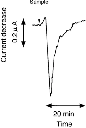
Fig. 1 shows typical response curve of the biosensor system for nitrate. After the stationary current was obtained, the nitrate standard solution was injected to the sample port of the flow line. The output current began to decrease within 30 sec, and a minimum current was obtained within 120 sec.
Figure 1. Response curve of the sensor system for nitrate. Nitrate standard solution: 50 mg/l of KNO3, sample volume: 100 µl, immobilized cell mass: 108 cells/cm2, pH: 7.0, temperature: 30°C, flow rate: 1.2 ml/min, glucose concentration: 0.1 g/l.
This phenomenon indicated that nitrate had passed through the cellulose nitrate membrane and was assimilated by the immobilized microorganism. P.
dinitrificans has been known as a versatile bacterium
capable of growth under various conditions. Heterotrophic growth occurs in the presence of a variety of carbon and energy sources, both under aerobic and anaerobic conditions with nitrate, nitrite, or nitrous oxide as terminal electron acceptor.12) In aerobic condition, oxygen consumption due to the respiratory activity of the microorganism caused a decrease of oxygen dissolved around the membrane. It consequently brought about the decrease in the output current of the sensor. The difference in current decrease between the maximum current obtained from sample solution and base line obtained from buffer solution was used as the measure of nitrate concentration. One assay was completed within 15 min.
Effects of assay conditions on the sensor response In general, the response of the biosensor was readily influenced by analytical conditions such as immobilized cell mass on the membrane, temperature, pH, flow rate, and glucose concentration. Effects of these parameters on the current decrease of the sensor were investigated.
Fig. 2 shows the effect of immobilized cell mass on the response of the sensor system. The response increased with increasing cell mass and the maximum current decrease was observed at 108 cells/cm2. Then the response gradually decreased again with cell mass. It was assumed that a rise in the sensor response was caused by a decrease in dissolved oxygen around the membrane due to increasing cell mass. On the other hand, the response decreased above 108 cells/cm2 with increasing cell mass. The increase of immobilized cell mass on the membrane also influenced the respiratory activity of microorganism, because, the concentration of nitrate in the standard solution was limited. The respiratory activity may have decreased due to the depletion of nitrate by increasing cell mass. For this reason, in subsequent experiments, the immobilized cell concentration of the membrane was prepared to be 108 cells/ cm2.
Figs. 3, 4, and 5 show the effects of pH, temperature and flow rate on the response of the sensor system, respectively. In Fig. 3, the response of the sensor increased with increasing pH in the range of 6.2 - 7.0 and was maximum at pH 7.0. Therefore, a pH of 7.0 was used in subsequent experiments. As the temperature of the buffer solution rose, the response increased as shown in
Fig. 4. Although the response became unstable at 37°C, the operation at 30°C was thought to be optimum for the system. The flow rate is also a critical parameter of the sensor system. In Fig. 5, the maximum response of the sensor was obtained at a flow rate of 1.2 ml/min, so the flow rate was adjusted to 1.2 ml/min in subsequent experiments.
Figure 2. Effect of immobilized cell mass on the current decrease of the sensor.
The experimental conditions were same as in Fig. 1, except for immobilized cell mass.
Figure 3. Effect of pH on the current decrease of the sensor.
The experimental conditions were same as in Fig. 1, except for pH.
H. Endo, Y. Nakazawa, Y. Nagano, H. Ren, and T. Hayashi 36
The effect of glucose concentration on the sensor response was also investigated (Fig. 6). In this system, PBS containing glucose was prepared since glucose was required for cell activity as carbon energy source. The response of the sensor increased with increasing glucose concentration in the range of 0.1 - 1.0 g/l, and then
decreased above 1.0 g/l with increasing glucose concentration. When the sensor system was operated at glucose concentration of 0.1 g/l, one assay was completed within 15 min. At higher concentrations such as 1.0 g/l, however, the response curve became broader, and one assay required more than 20 min. The reason of the phenomenon might be caused by the decrease of cell activity with increase of glucose. Therefore, the concentration of glucose was prepared to 0.1 g/l.
From these results, the sensor system was operated at the following optimum conditions; cell mass: 108 cells/ cm2, pH: 7.0, temperature: 30°C, flow rate: 1.2 ml/min, glucose concentration: 0.1 g/l.
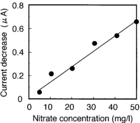
Calibration curve of nitrate
The calibration curve of nitrate is shown in Fig. 7. Each sample solution (100 µl) was injected into the flow line of the sensor system under the conditions described above and the current decrease was measured. Linear relationship was obtained in the range of 0.5 - 50 mg/ml. Monitoring of nitrate concentration during fish feeding The biosensor system was applied to the monitoring of nitrate concentration in fish feeding. Figure 8 shows the time course of nitrate concentration in fish tank determined by the sensor system and the conventional method. All analytical conditions were the same as shown in Fig.7. The nitrate level determined by the conventional
Figure 4. Effect of temperature on the current decrease of the sensor.
The experimental conditions were same as in Fig. 1, except for temperature.
Figure 5. Effect of flow rate on the current decrease of the sensor.
The experimental conditions were same as in Fig. 1, except for flow rate.
Figure 6. Effect of glucose concentration on the current decrease of the sensor.
The experimental conditions were same as in Fig. 1, except for glucose concentration.
method increased as time went by up to 15 days. The values determined by the sensor system also increased and the final value was almost the same (ca. 20 mg/l). The nitrate concentrations determined by the sensor were closely related to those by the conventional method. For a period from 12 to 31 days, the value determined by the sensor was slightly higher than that by the conventional
method. This phenomenon might be caused by the presence of nitrite in the fish tank. In general, P.
dinitrificans can also grow heterotrophicically in the
presence of carbon sources with nitrite.12) When the nitrite concentration for the same period was also measured by the spectrophotometric method,1) 4 - 25 mg/l of nitrite was found in the fish tank (data not shown). In the tank filter, ammonia was generally converted into nitrite and then into nitrate by nitrifying bacteria.
Since a bacterial ecology in the filter was unstable at the beginning of the fish feeding, nitrite was accumulated in the fish tank. At present, the sensor system was not very reliable at the beginning of the fish feeding. However, the system could monitor the nitrate level after nitrifying bacteria become stable in the tank filter. In conclusion, our proposed method using the biosensor could be used for the rapid determination of nitrate in fish tank. Further studies are in progress in our laboratory to find a solution for the above-mentioned problem.
References
1) Japanese Industrial Standard Committee: Testing methods for industrial water, JIS K 0102, 1976, 36p 2) T. Matsunaga, I. Karube, and S. Suzuki:
Electrochemical microbioassay of vitamin B1. Anal.
Chim. Acta, 98, 25-30 (1978)
3) I. Karube, Y. Wang, E. Tamiya, and M. Kawarai: Microbial electrode sensor for vitamin B12. Anal.
Chim. Acta, 199, 93-97 (1987)
4) M. Hoshi, H. Nishi, T. Hayashi, M. Okuzumi, and E. Watanabe: Development of biosensor for the determination total viable bacteria cell count.
Nippon Suisan Gakkaishi, 57: 281-285 (1991)
5) N. Li, H. Endo, T. Hayashi, R. Takai, and E. Watanabe: Development of a trimethylamine gas biosensor system. Biosens. Bioelectron., 9: 593-599 (1994)
6) H. Endo, A. Kamata, M. Hoshi, T. Hayashi, and E. Watanabe: Microbial biosensor system for rapid determination of vitamin B6. J. Food Sci., 60: 554-557 (1995)
7) H. Endo, K. Fujisaki, Y. Ohkubo, T. Hayashi, and E. Watanabe: A biosensor system for the determination of cell number of Enterococcus seriolicida.
Fisheries Sci., 62: 235-239 (1996)
8) M. Hikuma, T. Kubo, T. Yasuda, I. Karube, and S. Suzuki: Ammonia electrode with immobilized nitrifying bacteria. Anal. Chem., 52, 1020-1024
Figure 7. Calibration curve for nitrate.
The experimental conditions were same as in Fig. 1, except for nitrate concentration.
Figure 8. Time course of nitrate concentration during fish feeding.
The experimental conditions were same as in Fig. 1. ○ : sensor menthod, ● : conventional method.
H. Endo, Y. Nakazawa, Y. Nagano, H. Ren, and T. Hayashi 38
(1980)
9) I. Karube, T. Okada, S. Suzuki, H. Suzuki, M. Hikuma, and T. Yasuda: Amperometric determination of sodium nitrite by a microbial sensor. Eur. J. Appl. Microbial. Biotechnol., 15, 127-132 (1982)
10) T. Okada, I. Karube, and S. Suzuki: NO2 sensor which uses immobilized nitrite oxidizing bacteria.
Biotehnol. Bioeng. 25: 1641-1651 (1983)
11) Kosei-syou Seikatsueisei-kyoku: Jyousui Shiken Houhou, Nippon Suidou Kyoukai, Tokyo, 1985, pp. 261-263
12) H. W. V. Verseveld and A. H. Stouthamer: The genus
Paracoccus, in 「The Prokaryotes Vol.3 」 (ed. By A. Balows, H. G. Truper, M. Dworkin, W. Harder, and K. H. Schleifer) Spinger-Verlag. New York, 1992, 2321p
水環境のための硝酸モニタリング用バイオセンサー 遠藤 英明・中澤 康・長野 嘉之・任 恵峰・林 哲仁
和文要旨:硝酸濃度を測定するためのバイオセンサーシステムを開発した.本システムは,固定化微生 物膜(Paracoccus dinitrificans IAM 12479),クラーク型酸素電極,マイクロチューブポンプ,電流記録計よ り構成され,硝酸存在下における微生物の酸素消費を測定する原理に基づいている。本センサーの使用条件 を検討したところ,以下の条件が最適であった.菌体量:108 cells/cm2,pH 7.0,温度:30°C,流速:1.2 ml/ min,グルコース濃度:0.1 g/l.また,一検体の測定は 15分で可能であり,5 - 50 mg/l の硝酸濃度で検量線が 作成できた.さらに,本システムを魚飼育下における硝酸濃度のモニタリングに適用したところ,その測定 結果は従来法で得られた値とほぼ同様の経時変化を示した. キーワード:バイオセンサー,微生物センサー,モニタリング,硝酸,魚類飼育