Journal of the Operations Research Society of Japan
Vo!. 23, No. 4, December 1980
A GRAPHICAL
LOCATING THE
APPROACH
ORIGIN OF'
TO THE PROBLEM OF
THE SYSTEM FAILURE
Masao Iri, Katsuaki Aoki
University of Tokyo, Mitsubishi Heavy Industries Eiji O'Shima, and Hisayoshi Matsuyama Tokyo Institute of Technology, Kyushu University
(Received June 21, 1978; Final January 12, 1980)
Abstract This paper presents a way of formulating the problem of locating the origin of a system failure. A signed digraph is used for a mathematical model representing the innuences among elements of the system, and the concept of a pattern on the signed digraph is introduced for representing a state of the system. The representations are quit e rough and qualitative. The origin of a failure of the system can be l:Jcated in terms of these concepts. It is further pointed out that, even when the pattern can be observed partially, the assumption of a single origin of the failure enables us to restrict the possible range of the origin to some extent.
1. Graphical Representation of a System and Its State
In recent years, graphical representations have been proved to be useful for modelling and analyzing various kinds of systems in many fields of science and engineering.
When a directed graph (or, for short, a digraph) is used as a mathemati-cal model of a system, its nodes represent the elements of the system and its branches represent the immediate influences among the elements. In order to distinguish between positive and negativE influences (for instance, between reinforcement and suppression), a signed digraph is defined formally as fol-lows. As for the terminology and notation about graphs, we shall largely follow [1].
Definition 1. A signed digraph S is the composite concept (G, l/J) of (i) a digraph G which is the quadruple
(N, B,
a+, a-) of(a) a set of nodes N = {nI' n
2, " ' , nM}, (b) a set of branches B = {b
l , b2, " ' , bn},
296
and
M. lri. K. Aoki. E.O·Shimaand H. Matsuyama
(c) a couple of incidence relations
a+:
B ....
Nanda-:
B .... N
which make each branch correspond to its initial node and its terminal node, respectively,(ii) a function ~ ': B .... {+, -}, where ~(b ) (b E B) is
K K called the
sign of
branch b . ~
K
Example 1.
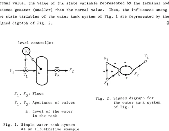
An illustrative example of a signed digraph: --- Let a branch with sign +(-) indicate the relation such that, if the value of the state variable represented by the initial node of the branch is greater than the normal value, the value of thE. state variable represented by the terminal node becomes greater (smaller) than the normal value. Then, the influences among the state variables of thE' water tank system of Fig. 1 are represented by the signed digraph of Fig. 2.level controller
PI' P2 : Flows
VI' V2: Apertures of valves L: Level of the water
in the tank
Fig. 1. Simple water tc.nk system as an illustrative example
Fig. 2. Signed digraph for the water tank system of Fig. 1
We shall assume that the state of the system is specified by whether the quantity associated with each element (to be called the state variable of the element) t,~Kes the "norma]" value, is greater or smaller than it. The three states of the quantity arE' designated, respectively, as "0",
"+"
and "-". Thus, the state of the system is described by assigning any of the three sym-bols 0, + and - to each node of the signed digraph representing the str~ctureof the sys tern. Formally, the "ta tes may be defined in terms of "pa t terns" as follows.
Locating the Origin of the System Failure 297
Defi niti on 2.
A patter>n'on the signed digraph S=
(G, 1jJ) is a functionw N -+ {+, 0, -}. w(n ) (n a. a. E N) is called the sign of node nN • 00
u.
Example
2.. In the water tank system of Fig. 1, a state of the system can be described by assigning the sign 0, +, or - to each node according as the value of the variable corresponding to the node lies within, above or below the prescribed interval of tolerance, respectively. If any node has a sign +or -, the system is in failure. 00
For a given signed digraph and an observed pattern on it, it is natural to consider that the manner of propagation of the failure is represented by the cause-effeut graph (or, for short, the CE graph) defined as follows.
Definition 3.
Given a pattern w on a signed digraph S+
-b is said to be consistent (with w) i f w(Cl b )1jJ(b )w(Cl "ID )
K K K K
(G, 1jJ), a branch +, and a node nO. is said to be valid if w(no.)
!
0, where the operations on signs are defined as usual, Le., we assume (+) x (+) = (-) x (-) = + and (+) x (-) = (-) x (+) = -The subgraph G~' of G which consists of all the valid nodes and all the con-sistent branches is called the CE graph for the pattern w on the signed digraphS.
When the CE graph is decomposed into strongly connected components with the partial order among them [1), the system failure is reasonably thought to originate from among the elements in those components of the CE graph which are maximal with respect to the partial order. (The node set of a digraph is classified intc equivalence classes with respect to the equivalence relation such that two nodes are equivalent, Le. they belong to the same class, if and only if there is a directed path from anyone of them to the other. A
"strongly connected component" of the digraph is the subgraph consisting of all the nodes cf an equivalence class and of all the branches whose end nodes both belong to the class. The relation, defined among the strongly connected components by the stipulation that a component is in the relation to another if and only if there is a directed path from a node of the former component to a node of the latter, is a partial order. There is at least one strongly con-nected component which is maximal with re'3pect to this partial order.)
The CE graph can be considered to de:3cribe the way of propagation of the failure so long as the propagation is explicit on the pattern, i.e. there is no influence through a node with sign O. Unfortunately, however, if the sys-tem has some controlled elements, it may happen that the failure propagates
298 M. Iri, K. Aoki, £.0 'Shima and H. Matsuyama
through a node with sign 0, as is illustrated in the following example.
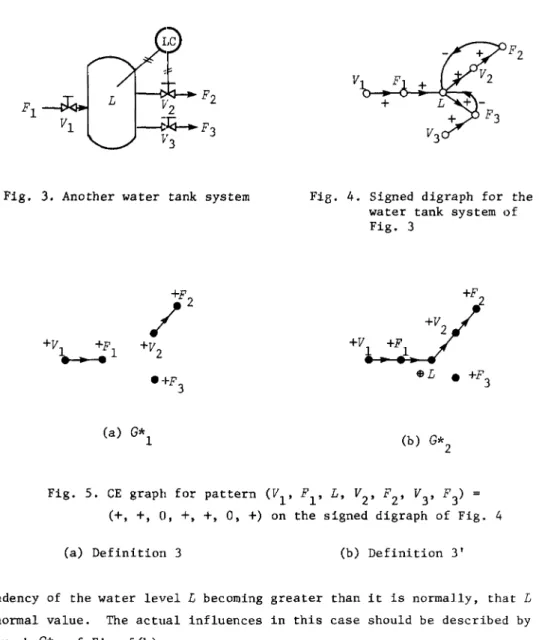
Example 3.
For the water tank system of Fig. 3, the influences among the state variables are represented by the signed digraph of Fig. 4. In case the observed signs of the variables (Vl, Fl,
L, V
2
, F
2
, V
3
, F
3
)
are (+, +, 0, +, +, 0,+),
the CE graph for this pattern would be a graph of Fig. 5(a) according to Definition 3. However, it is because the level controller suppresses theLp
Fl
V
2 2~J4.-.F3
V 3
Fig. 3. Another water tank system
+V +F ~l e+F 3 (a)
G*l
F2 VFi8. 4. Signed digraph for the water tank system of Fig. 3
Fig. 5. CE graph for pattern (V
l, FI, L, V2, F2, V3, F3) = (+, +, 0, +, +, 0, +) on the signed digraph of Fig. 4
(a) Definition 3 (b) Definition 3'
tendency of the water level
L
becoming greater than it is normally, thatL
has a normal value. The actual influences in this case should be described by the digraphG*2
of Fig. 5(b).Locating the Origin of the System Failure 299
In order to take account of the spe,:ial roles of controllers and con-trolled elements, it is necessary to distinguish some elements of the system as controlled elements, and to extend the formal definitions of a signed digraph, a pattern and a CE graph as follows.
Definition 1'. A signed digraph S is the composite concept (G, 1jJ, C, T) of
(i) a digraph G
=
(N, B,
a+, a-), (ii) a function 1jJ : B .... {+, -}, and(iii) a set of controlled nodes
C
=
{n , n , " ' , n } (~ N) to each of which al a2 ala set of control-information carrying branches T)(n )
(~o+n
) (i=
1,a
i
a
i" ' , l)
is associated, where o+n a.
'l-denotes the set of branches whose
initial node is n a.
'l-Defi ni ti on 2'. A pattern on a signed digraph S is a function 1jJ
0, -, $, 9} such that
wCN -
C) 5 {+, 0, -}.N .... {+,
/Xl
Definition 3'. Given a pattern won a signed digraph
S,
a node is said to be valid i f w(n ) f 0 and a branch b is said to be consistent i f ba K K
satisfies one of the following five conditions (i) ~ (v):
(1) (ii) (iii) (iv) (v) W(a+b ) K W(a-b K) w(a-b ) K b is Cl K - +
-+, w(a b ) = ±, and w(a b )1jJ(b )w(a b )
- K K K K
$ and W(a+b
K)1jJ(bK) +;
9 and w(a+b )1jJ(b )
K K
control-information carrying branch, Wca+b K) 1jJ(bK)w(a-b
K)
=
+;b is Cl control-information carrying branch, Wca+b
K) K 1jJ(b )w(a-b ) = - . K K +,
,
$ and 9 andThe subgraph
G*
ofG
which consists of all the valid nodes and all the consistt=nt branches is called the CE graph for the pattern w on the signed digraph S.In the above definition, sign $(9) might intuitively be interpreted as representing "the st-R.te of a variable which would have sign +(-) without c:on-trol but which is not seen abnormal due to the operation of conc:on-trol".
300 M. [ri, K. Aoki, E.O'Shimaand H. Matsuyama
2. Formulation of the Problem of Locating the Origin of a ,System Failure If the observed pattern is a failure pattern, Le. if there are some nodes with nonzero signs, the CE graph for the pattern can be used to describe the structure of the chain of propagation of the failure, and the problem of locating the origin of the failure is reduced to that of finding the maximal strongly connected components of the CE graph.
However, it is usually the case that some of the signs of nodes cannot be measured or observed due to physical, technical and economical reasons, so that the set of nodes of the signed digraph should be partitioned into two subsets: one (to be denoted by N
M) consisting of observed nodes whose signs are measured or observed, and the other (Le. N - N
M) consisting of unobserved nodea whose
signs are not known.
A method which has been proposed to cope with this situation is found in [2]. By that method we eliminate unobserved nodes from S beforehand and con-struct a signed digraph
S'
whose nodes are all observed nodes and whosebranches represent indirect influences transmitted through unobserved nodes in S. Then, S' is regarded as the model of the system. Fig. 6 is an illustrative example of the elimination of unobserved nodes.
+
S
Fig. 6. Example of the elimination of unobserved nodes (e: observed, 0 : unobserved)
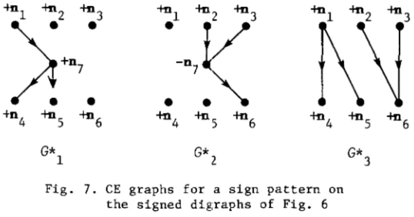
However, this method has obvious disadvantages. In fact, the two signed digraphs
S
andS'
of Fig. 6 give different interpretations to a sign pattern on the observed nodes, e.g. to w(n.)=
+
(i=
1, " ' , 6 ) . Starting from S we
1.-have G*l or
G*2
of Fig. 7 as the CE graph according as we assume w(n7)
=
+ or w(n7)
= -,
whereas fromS'
we haveG*3'
It is seen that this failure pattern has four or five independent origins on the basis ofS
on the one hand" and onLocating the Origin oj the System Failure 301
the other, it has three independent origins on the basis of S'. This evidences that the elimination of unobserved nodes generally results in loss of infor-mation, which might cause the essential structure of the problem to be missed. Moreover, sinee the elimination of nodes of a graph increases, in general, the number of branches, it is not suitable for the treatment of large graphs from the point of view of computational complexity.
-to 1 -+nZ -+n3 +n l -+n Z -+n3
f\ \J'
)+D7
•
•
-DV
7 • " ' .•
•
•
-t°4 -+nS -+n6 -+n4 -+nS -+n6 -+n4 G* 1 G* 2Fig. 7. CE graphs for a sign pattern on the signed digraphs of Fig. 6
-+nS -+n6 G*
3
Therefore, we shall propose to deal with the given signed digraph and a partial pattern on it (partial in the sense that signs are assigned only to part of the nodes) with no modification, and to restrict the possible locations of the origin of the failure as far as possible. In general, any pattern obtained from a given partial pattern by supplementing in an arbitrary way the signs of the nodes to which the signs are not a priori given, may possibly take place. However, we must exclude from consideration most of those patterns which would not reflect practical situation. In so doing, the following fun-damental presumption seems to be natural and it indeed works very effectively.
Presumption of a single origin:
There is a single origin of the system failure.
The CE graph G* for the pattern corresponding to a system failure satis-fying this presumption should be a rooted digraph, which is defined as follows.
Defini ti on 4. We shall call a digraph G
=
(N, B,a , a )
+
-
a rooted d~~graphif G has a node l!Il I). such that t 0 every no e d Os th ere is at least one direcl_-ed path from 01).' (It is well known that a rooted digraph is a graph having only
one maximal strongly connected component.)
302 M, [ri, K. Aoki, Ef)'Shima and H. Matsuyama
Definition 5.
LetS
=
(G,
~) (G=
(N,
B,a , a
+
-
»
be a signed digraph. A partiaZ pattern on S with domainN
is a set of signs of the nodes inN,
whereN
is a subset of the set N of nodes, i.e. it is a function w* :N ....
{+, 0, $,Q}.
If w* is a partial pattern with domainN,
an expanded pattern ofw*
is a patternw :
N ....
1+,
0, -, $,Q}
such thatwiN
=
w*.
Then the problem of locating the origin of a system failure under the pre-sumption of a single origin is formulated mathematically as follows.
Problem.
Given a signed digraph S and a partial patternw*
with domainNM
of observed nodes, to enumerate the expanded patterns ofw*
which make the corresponding CE graphs rooted.3. An Algorithm for Locating the Origin of a Failure
The solution of the problem formulated in the preceding section may be
found in principle by enumerating the CE graphs for all the 3
1N -
NMI possible expanded patterns and by testing whether each CE graph is rooted or not. However, such a primitive method would require a prohibitively long time if it were carried out on a computer, so that we have to devise a practically more efficient algorithm.For that purpose, we consider a partition of the set
N -
NM of unobserved nodes into two subsets: one being the setNA
of nodes whose signs are tenta-tively assumed (to be called assumed nodes), and the other being the set Nyof nodes whose signs are not yet assumed (to be called non-assumed nodes). We then ~onsider, for the partial pattern with the set of observed nodes and assumed nodes as the domain, the quasi-CE graph consisting of all those branches which may belong to the CE graph for at least one of the expanded patterns.
Definition
6. Let S be a signed digraph and w* : NM uNA"" {+, 0, -, $, Q} be a partial pattern on S with the union of the set NM of observed nodes andthe set N A of assumed nod,es as the domain. A vaZid node is a node DC( E NM uNA
with W*(DC() = +, -, $ or Gl, and a semi-consistent branch is a branch which can be a consistent branch LUC at least one of the expanded patterns of
w*,
i.e.branch b
Locating the Origin of the System Failure 303
conditions:
it is valid;
(i) - (v) of Definition 3' in §l with w* in place of w.
The sub graph
G
of G consisting of all the valid nodes and the non-assumed nodes and of all the semi-consistent branches is called the quasi-CE graph for partial pattern w* on signed digraphS.
Definition
7. LetG
be a quasi-CE graph. An essential component of (; is a strongly connected component containing at least one valid node. An unessential cornponent ofG
is a strongly connected component consisting of non-assumed nodes only.The follo1,ling theorem is almost evident but useful for developing a plcac-tical algorithm.
Theorem 1.
Let S=
(G, 1jJ) be a signed digraph andG
be the quasi-CE graph for a partial pattern w* with the set of observed nodes and assumed nodes as the domain. Furthermore, let G* be the CE graph for an arbitrary expanded pat-tern w of w*. Then, the number m of max:~mal essential components ofG
does not exceed the numberm*
of maximal strongly connected components ofG*.
For the proof of Theorem 1, we may make use of the following two lemm~s which are easily proved.
Lenma 1.
Every strongly connected eomponent of a digraph remains to be a component or is divided into several components if some of the branches are removed (i.e. opened).Lemma 2.
LetG
=
(N, B,
a+, a-)
be an acyclic digraph andN'
a subset of N. If the set of branches from a node of N - N' to a node of N' is empty, Le.{b
K
Ib
K EB,
a-b
KEN', a+b
K EN - N'}
=0,
then there is at least one node ofI.J' which has no branch ending at it.
Proof of Theorem 1:
Ifm
=
0, the theorem holds. In casem
2 1, let W be the set of all those nodes of any maximal essential component ofG
which are valid inG*.
By thp definition of an eS.5ential component, W is not empty, and by the definition of a semi-consistent branch, expanding the pattern (i.e.304 M. Iri, K. Aoki, ED'Shima and H. Matsuyama
assigning new signs to nodes) does not give rise to new branches. Therefore, N is partitioned into strongly connected components of G* by Lemma 1. Let the partition be W
=
Wl U N2 U '" U Nk.
Now, let us consider the digraph GO which represents the partial order among the strongly connected components of
G*.
Then, there exists no branch connected to the nodes of GO corresponding toNi's (i
1, " ' , k) from the other nodes. Therefore, by Lemma 2, there is a node of GO corresponding to anN. at which no branch ends. Since the strongly connected component of G*
1-corresponding to this node is maximal, we have proved that, for each maximal essential component of
G,
there exist one or more maximal strongly connected components ofG*,
which are obviously disjoint. Hence follows the theorem. Q.E.D.Coro 11
ary 1.
Let m, G* be the same as in Theorem 1. If m '" 2, G* is nota rooted digraph.
By means of this corollary we know that, if m ~ 2 for a partial pattern, none of the CE graphs for its expanded patterns can be a rooted digraph, with-out examining all the expanded patterns.
We shall propose an origin-locating algorithm using Corollary 1 combined with the depth-first search technique, as is outlined in the following.
Origin-locating Algorithm:
To begin with, set NA= 0.
At each step of the iteration, two cases are possible.Case A: The quasi-CE graph for the current partial pattern has two or more maximal essential c::>mponents. In this case, we stop expanding the current partial pattern and examine the possibility of changing the assignment of a sign to one of the assum,=d nodes.
Case B: The number of maximal essential components of the quasi-CE graph for the current partial pattern equals one or zero. This case is further divided into two subcasea.
Case Bl: There are one or more non-assumed nodes. In this case we choose one of them to which we assign a sign.
Case B2: There is ·:to non-assumed node. In this case we output the cur-rent partial pattern (which is a (nonpartial) pattern) and the CE graph for it, and then go over to the possibility of changing the assignment of a sign to one of the assumed nodes.
10
Locating the Origin of the System Failure 305
(
STAR'Q01
Input S and w*I
21
Pre-processingI
+
31 Generate quasi-CE graph G
I
(C It n ; P + 0 ; S + 0)
151
Sa+ O ; Modify GI
a a a
11 for every node Da in the ~
maximal unessential~ components; Modify G 141 S + +1 ; a ~--- I10dify G =+1
Decompose
G
into.-~o
strongly connected 4 components and
determine the partial order among them
(Pop up the
+
element DyNumber of maximal on the top of
=0 ~2 C ; Sy + ,~)
--
\
essential ,:omponents 13of G? until Da with
Pa = 1 is found
=1 on the top of C
Number of maximal C is enpty
~l unessential components
6
of G?
C " Da ; =0
(
STOP)
Pa +-1 ;
Sa +--1 ; Assign the signs to the
Modify G 7 nodes Da according to (where Da is (H) of Theorem 2; Pa +- 0 any non-assumed node, in a maximal component if possible)
~~
..
Do there rE:main 9 8 non-assumec: nodes? NO e-YESFig. 8. Outline of the algorithm for locating the origin of a system failure
306 M. Iri, K. Aoki, £.0 'Shima and H. Matsuyama
Since, in an acyclic graph, a node at which no branch ends forms by itself a maximal strongly connected component, we readily have the following theorem
(Theorem 2), which is useful for making the algorithm more efficient.
Theorem 2.
Suppose that the quasi-CE graphG
for a partial pattern on a signed digraph has a single maximal essential component. Then, the following two conditions must be satisfied by any expanded pattern to make the eorre-sponding CE graphG*
a rooted digraph.(i) Every node of any maximal unessential component of
G
is assigned signo
in the expanded pattern.(ii) For a strongly connected eomponent of
G,
if there is only one branchb
K which ends at a node in that component and starts from a node in
another component, the deletion of b
K will make that component
maxi-mal. Hence, if one of the ends of b
K is a valid node and the other is non-assumed node, then the sign of the non-assumed node in the expanded pattern may be determined so as to make b
K consist!~nt. 00
An outline of the "origin-locating algorithm", with the improvements sug-gested by Theorem 2 incorporated, may be described as the flow chart of Fig. 8, where, for the sake of simplicity, all the controlled nodes are supposed to be observed. The roles played by the stacks and arrays in the flow chart are as follows.
In the "pre-processing" block 121, when the value of a state variable cor-responding to a controlled node is within the specified tolerance (i.e. its sign is either 0, $ or Q), we open all the branches starting from the node except those carrying control information, and then regard the controlled node as an unobserved one.
C is a stack with the depth equal to the number of nodes. Assumed nodes are pushed down in C each time when a sign is assigned. S as well as P is a
one-dimensional array with the size equal to the number of nodes. We put Sa
=
*
if Ba is a non-assumed node, and Sa is equal to its sign if Da is an assumed node.In blocks
[lJ
and121,
we assign the signs to the relevant nodes according to (i), (ii) of Theorem 2, where we put P a=
0 for those nodes Da' In blocklJ],
we pop up the nodes in stack C until a node l!Il with P=
I (Le. a node with ana a
"arbitrarily" assigned sign)' appears on the top of C.
Block [!jJ contains a routine to decompose a digraph into strongly connected components. The algorithm proposed by R. E. Tarjan [3] is now regarded as one of the most effi~i~nt.
Locating the Origin of the System Failure 307
It will not be difficult to see that we can enumerate all the possible sign-assignments by the help of the stack
C
together with the auxiliary arrays Sand P.Example 4.
Let us take up again the system of Fig. 3 in Example 3, which is modelled into the signed digraphS
of fig. 4. Furthermore, let us assume that nodes VI' LandF
Z
are observed, the other nodes being unobserved, and that node L is controlled where control information is carried by the branch to node VZ• Now, suppose pattern w* : (VI' L, FZ)
r---+
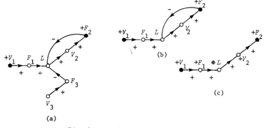
(+, 0, +) is observed.After the preprocessing block ~, we have the initial quasi-CE graph shown in Fig. 9(a), where node L is regarded as an unobserved node. Since the digraph of Fig. 9(a) ha.s two maximal strongly connected components, Le. {VI} and {V
3},
the former being essential and the latter not, node V3 is assigned sign
°
in block[1/,
and the quasi-CE graph is modified by removing node V 3 and the branch incident to it. In the resulting quasi-CE graph {F3} is again an
unessential maximal component, so that it is removed together with the incident
+
+
(b)
Fig. 9. Example of the algorithm
+
(c)
branch. Then ~le have the quasi-CE graph of Fig. 9 (b). This digraph has only one essential naximal component, so that we apply (ii) of Theorem Z in block
I2l to assign
+
to node F l' and then $ to L. Then, the branch from node F 2 toL becomes inva:,id and is removed from the graph. Thus, by applying (ii) of Theorem Z again, we have the final CE graph shown in Fig. 9(c), which is unique in this case. The expanded pattern (uniquely determined in this case) is u) :
(VI' L, FZ; F
I·, VZ' V3, F3) f---+ (+, $, +; +, +, 0,0). Thus, we can conclude
308 M. Iri, K. Aoki, £.0 'Shima and H. Matsuyama
of valve V l .
4. Related Problems
An error-detecting or error-correcting code is famous in the context of error/failure detection and diagnosis. That is a code which is used for improving the reliability of the information transmission through a noisy chan-nel. By taking advantage of a special algebraic structure of the code,
under
the asswnption that the Y!wnber of
errorsis within a specified bound,
'Ne can detect the existence of (,rrors or clarify their locations.Our problem has a common feature with an error-detecting (-correcting) code in that the location of the origin of a system failure is to be found on the basis of the information obtained by some observation (Le. a pattern of signs of observed nodes)
under the asswnption of a single origin of failure.
But there is a basic difference between the error-detecting (-correcting) code and our problem. In the former, it is possible --- and i t is the mostimpor-tant point of the theory --- to design an artificial structure which enables us to detect (correct) errors, whereas, in the latter, the structure oE the system as well as the observability/unobservability of the signs of nodes are a priori given.
A fault diagnosis of a logical circuit is also well known. The location of fault is determined by means of a combination of many tests (each of which is an input-output sequence pair) [4]. Thus, the problem of fault diagnosis of a logical circuit and our problem have the same purpose, i.e. to determine the origin of a failure in a
given
system. However, there is much difference between the two problems. In our problem, only the information given in the form of cl pattern of the signs of observed nodes is available when a failuretakes place, whereas, in the diagnosis of a logical circuit, arbitrary signal sequences (which are prepared especially for the purpose of diagnosis) may be input to the system in order to obtain useful information.
5. Discussions on the Problems to be Solved
In this paper we presented the concept of a signed digraph and a pattern on i t as a mathematical model for describing roughly a system and its state, and formulated the problelTI of locating the origin of a system failure in terms of those concepts. A practical algorithm for the problem was also proposed.
Locating the Origin of the System Failure 309
The present formulation of the model is motivated through an attempt to establish a systematic approach to the automatic diagnosis of the failures of chemical plants. However, the model seems to be applicable to a wider vari.~ty of engineering as well as social systems.
There remai.ns, of course, much to be further developed both from the mathematical and the practical points of view.
Mathematically, the present version of origin-locating algorithm is rather primitive. For example, a part of a chemi.cal plant was modelled into a digraph with 21 nodes and 62 branches, of which 6 nodes are observed and 3 nodes are controlled. Th,= origin-locating algorithm generated about 20,000 quasi-CE graphs and examined their connectivity. It took about 20 minutes on FACOM 230/45 operating under FORTRAN IV monitor.
The necessary time will increase very rapidly, i.e. exponentially, as I:he size of the graph, especially the number of unobserved nodes and controlled nodes, increases. However, we can introduce various devices similar to those enunciated in Theorem 2 to greatly cut do.m the number of quasi-CE graphs to be examined. Designing such devices will afford interesting and useful resE~arch subjects in graph theory. In fact, by adding a few such devices to the algo-rithm, we could solve the same problem in less than 10 seconds. For a given specific sys tern, the more of its special ~:truc tures we take advantage of, the more devices shall we be able to find to speed up the algorithm.
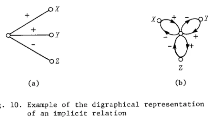
There will be a number of problems when we make a model of a real system. For example, an implicit relation such as f(x, y, z)
o
among state variablesx
xw
y
y-
+
-
+
Z Z (a) (b)Fig. 10. Example of the digrc.phical representation of an implicit relation
cannot be repreBented in the unique way by the branches which connect the nodes reprec;enting variahlAs x, y, z. However, if the signs of partial derivatives of
f
with respeet to the variables are kncwn, say,f
> 0,f
> 0 andf
< 0,310 ,If, Iri. K. Aoki. £.0 'Shima and H. Matsuyama
it may be possible to re:nesent the implicit relation by a bipartite graph with a dummy node as shO'.VIl in Fig. 10(a), and then by a signed digraph as shown in Fig. 10(b).
In the case that thl~ method is applied to a continuous system such as a chemical process, the influence relations and the values of state variables are to be quantized into two or three levels. A standard method should be looked for for the quant:ization.
It is clear that, the more nodes are observed, the smaller will be the part within Ivhich the or:igin of failure is confined and the faster will the algorithm run. However, in practice, the number of observed nodes is limited by physical, technological and economical reasons. Here arises the problem of establishing a criter:ion according to which observed nodes are to be dis-tributed. This leads us to a problem of synthesis of a system in contrast with the problem of analysis considered in this paper.
The authors are trying to implement the method presented in this paper in an actual chemical plant, where they are finding practical solutions to the problems discussed in this section. The theoretical results, as well as the practical, obtained in the course of the trial will be published elsewhere before long.
The authors thank the referees for their valuable comments and sugges-tions, by which the manuscript of the paper was substantially improved.
This work was supported in part by the Grant in Aid for Scientific Research of the Ministry of Education, Science and Culture of J&pan.
References
[1] Iri, M.: Network Flou), Transportation and Scheduling --- Theory and Algo-rithms. Academic Press, New York, 1969. See also: Iri, M.: Theory of Graphs and Its Applications [I]-[V] (in Japanese), Journal of the Insti-tute of Electronics and Communication Engineers of Japan, Vol. 54, No.12 -Vol.55, No.5 (Dec. 1971 - May 1972).
[2] Andow, P. K., and Lees, F. P.: Process Computer Alarm Analysis: Outline of a Hethod Based on List Processing. Transactions of the Institution of Chemical Engineers, Vol.53 (1975), 195-208.
[3] Tarjan, R. E.: Depth-first Search and Linear Graph Algorithms. SIAM Jour-nal on Computing, Vol.l, No.2 (June 1972), 146-160.
Locating the Origin of the System Failure 311
[4] Chang, H. Y., Manning, E. G., and Metze, G.: Fault Diagnosis of Digital Systems. Wiley-Interscience, 1970.
References added in proof
Nasao IRI: Department of Mathematical Engineering and Instrumentation Physics, Faculty of Engineering, University of Tokyo, 7-3-1 Hongo" Bunkyo-ku, Tokyo, Japan 113.
[5] Iri, M., Aoki, K., O'Shima, E., and Matsuyama, H.: An Algorithm for Diag-nosis of System Failures in the Chemical Process. ComputeY' and Chemical EngineeY'ing (to appear).
[6] Umeda, T., Kuriyama, T., O'Shima, E., and Matsuyama, H.: Graphical Approach 1:0 Causes and Effects Analysis of Chemical Processing Systems. The 12th EUY'opean Symposium on ComplAteY' Applications in Chemical Engi-· neenng, Hontreux, April 1979.