Photochemistry in Layered Micro-environment
VIVEK RAMAKRISHNAN
Tokyo Metropolitan University
Doctor of Philosophy
2014
ii
Abstract
Polyfluoroalkylated azobenzene derivative (C3F-Azo-C6H) is synthesized and intercalated within the interlayer of clay (Sumecton SA). The hybrid formed is characterized using X-ray diffraction (XRD) and thermogravimetric (TG-DTA) analysis.
Photoreaction within the interlayer is monitored and phenomenon is compared that of potassium hexaniobate hybrids.
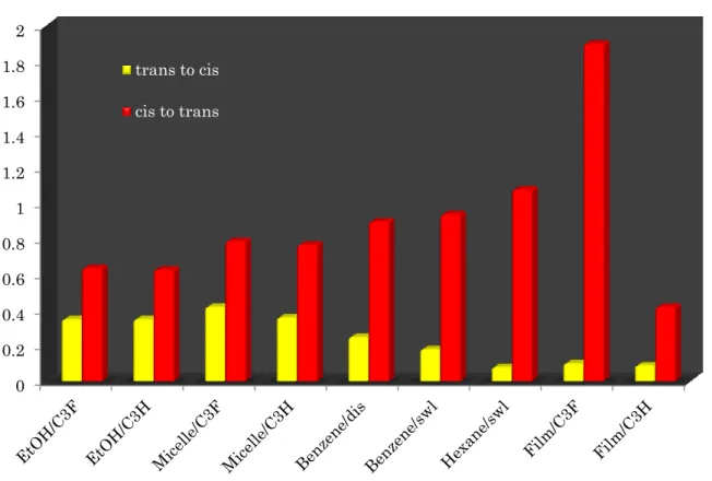
Systematic study on the reactivity of the isomerization in molecular level under various microenvironments viz. ethanol, micelles, clay hybrids in dispersed swelled and film state is carried out and photoisomerization characteristics are compared among these systems. Solvent penetration into the interlayer spacing of clay hybrid is studied in hexane and benzene. We have seen unusual enhancement of reactivity for cis to trans isomerization and gradual decrease for trans to cis isomerization when moving from monomeric state to hybrid system.
The quantum yield of photo-isomerization was carried out for hybrid system under high pressure condition. Very interestingly unusual phenomenon of reactivity exceeding many times to that of unity was observed for cis to trans isomerization. Trans to cis isomerization was found to be restricted at very high rate. This observation was very much correlated to that of steady state reactivity at ambient conditions.
In that viewpoint, activation energy for thermal cis to trans isomerization was measured
iii
for C3F-Azo-C6H in ethanol, micelle and clay hybrid dispersed in benzene and film state. The results showed the periodic decrease in activation energy from monomeric state to hybrid system in film. As we have seen in quantum efficiency measurements, the high reactivity for thermally favourable isomerization is accounted by the difference in
potential energy surface which depends on the micro-environment for the cationic azobenzene surfactant, the central molecule under study.In order to have a concrete idea, excited state dynamics in each micro-environment is studied using nanosecond laser flash photolysis. The transient absorption and decay curve spectra in ethanol, micelle and hybrid dispersed in benzene showed a clear disappearance of thermally equilibrated intermediates and small rise of cis form. In this case only process involved is photoisomerization and this can be easily read out. Unlike in benzene, transient absorption spectra of hybrid dispersed in hexane shows the cooling down of intermediates. The difference in results of benzene and hexane dispersed hybrid sample is accounted by the phenomenon of solvent penetration. The crucial investigation is in film state of hybrid in air where we observed the unusual reactivity of isomerization. The hybrid system involving both C3F-Azo-C6H and C3H-Azo-C6H is deeply studied. Both transient absorption spectra and decay profiles showed the presence of time dependent relaxation within the clay hybrid. A distinct difference in dynamic behaviour was also observed due to the polyfluorinated chain as well.
Nanosecond laser flash photolysis evidently shows the thermally equilibrated species formed within nano-layered microenvironment. To confirm the transient local ‘heating’
in the molecular level, Rhodamine B and Ru(bpy)
32+co-intercalated surfactant/clay
iv
hybrid were prepared. Both molecules were reported to have robust dependence of emission decay on temperature. Rhodamine B co-intercalated hybrid showed micro-dependent changes of its fluorescence with reversible isomer switching with much shortened lifetime than in solution. But in Ru(bpy)
32+analogue, lifetime is as a whole is shortened than in solution and reversible isomer switching effect on emission decay were less dominant than local heating phenomenon, whereas in former case fluorescence quenching could be assigned to steric effect operated in nano space which is a predominant factor than thermal effect.
Nanosheet sliding, high reactivity in layered micro-environment in film state and under
high pressure and presence of thermally equilibrated species observed in laser flash
photolysis clearly evidence a set of a co-operative phenomenon happening in the
nano-layered microenvironment constituted together with polyfluorinated surfactants. It
is further evidenced by the decay kinetic analysis of the dye co-intercalated
clay/surfactant hybrid.
v
Declaration
I declare that the work presented in this thesis is my own unless otherwise stated by a reference.
Vivek Ramakrishnan
vi
First of all thanks to almighty god for all the power and courage for carrying out this work and pursue my dreams.
It is with great pleasure that I extend my deep sense of gratitude to Prof. Haruo Inoue, my supervising scientist for suggesting the research problem and for his valuable guidance, encouragement and constant support. I appreciate all his contributions of time, ideas, and funding to make my Ph.D. experience productive and stimulating. The joy and enthusiasm he has for his research was contagious and motivational for me, while pursuing Ph.D., even during the tough times.
I would like to thank Prof. Hiroshi Tachibana for his help and encouragement. He gave me valuable ideas especially when dealing with theoretical aspects of photochemistry.
I would like to thank Prof. Hirohisa Yoshida, Prof. Shinsuke Takagi, Prof. Takashi Takei for their kind support and valuable advice in finalizing my research theme.
The whole hearted help provided by Prof. Tetsuya Shimada were also gratefully acknowledged. He kindly helped us in maintaining laser system.
Most importantly I’m thankful to Dr. Yu Nabetani, who guided me, teaching the spectroscopic instrumentation, maintenance and analysis and I very much appreciate his enthusiasm, intensity and willingness to help me in solving research problems.
Dr. Daisuke Yamamoto kindly helped me in many of the laboratory instruments and it
was very productive in collaborating with him in certain experiments. Dr. Youki Kou
vii
was my tutor during the course and he helped me in enormous way personally to settle down here. I’m also thankful to Mr. Shin Sasamoto who is an alumni of Inoue laboratory whose preliminary results were very useful and gave us direction and motivation while solving research problem..
I express my indebtedness to all members of the Inoue laboratory, Ms. Masae Asano, secretary to Prof Inoue, who gave me constant support throughout the studies and life right from beginning. I extend my sincere gratitude to Mr. K. Kurimoto, Ms. Hayasaka, Mr. Y. Gomi, Mr. R. Iko, Mr. S. Matsukura, Mr. S. Nakatani, Mr. Y. Takeda, Ms. A.
Uchikoshi, Mr. S. Sagawa, Ms. Onuki, Mr. F. Kuttassery, Mr. T. Hirano, Mr. H.
Horiguchi, Mr. S. Mathew, Mr. S. N. Remello, Dr. P. V. Nair, Mr. A. Thomas, Mr. S. Z.
Hassan for their thoughtful suggestions and wholehearted assistance during the tenure of my work. I wish to thank all my friends for their wholehearted support. I also thank friends in Tokyo Metropolitan University for their cooperation.
I am extremely thankful to Tokyo Metropolitan Government, Asian Human Resource Fund and International Student Support team at Tokyo Metropolitan University for arranging my project work and their constant support.
I am extremely thankful to Prof. Suresh Das, Director of National Institute for Interdisciplinary Science and Technology (NIIST), Trivandrum, India who was my guide during master’s project.
I would like to express my sincere gratitude to the kindest person I ever met, Prof. P.A.
viii
Lastly but most importantly, I would like to thank my parents for all their love and support and encouragement. For the passion and curiosity towards science is triggered by their nurture and care. For my sister was a great support for me and guided in all difficult times of personal and academic life.
I also like to thank all individuals who came in my life and encouraged me throughout my carrier.
Vivek Ramakrishnan
September, 2014
ix
Dedication
I dedicate this thesis to the absent from my life and present always in my heart my Uncle,
Vijayan Okkott (1972-2014).
The endless love that you through and the principles that you installed in me have
created my views toward life and learning. I am sure this achievement would make you
proud.
x
Abstract……… .ii
Acknowledgement………... .v
1. General Introduction………. 01
1.1 Microenvironments for chemical reaction……….. 01
1.2 Inorganic-organic hybrid compounds……….. 02
1.3 Photomechanical systems……… 07
1.4 Research background………... 11
1.5 Efficient Photomechanical System……….. 17
1.6 References……… 19
2. Preparation, characterization and preliminary photophysical properties of C3F-Azo-C6H and its hybrid with clay ……….. 23
2.1 Introduction……….. 23
2.2 Experimental……… 23
2.3 Synthesis of C3F-Azo-C6H………. 25
2.4 Intercalation and characterization of C3F-Azo-C6H into the interlayer spaces of SSA……….. 28
2.5 Photoreaction of Clay/C3F-Azo-C6H hybrid……….. 33
2.6 References……… 36
3. Reactivity and photoisomerization behaviour of C3F-Azo-C6H and C3H-Azo-C6H in various microenvironments……….. 38
3.1 Introduction……….. 38
3.2 Experimental……….39
xi
3.3 Principle………39
3.4 Calculation of quantum efficiency of photoisomerization………41
3.5 Results and discussion……….………..43
3.5.1 Photoreactivity of C3F-azo-C6H in different microenvironments...43
3.5.1.1 C3F-AzoC6H/ethanol - monomeric state………....43
3.5.1.2 C3F-Azo-C6H/water - micellar state…..………..………..46
3.5.1.3 Clay/C3F-Azo-C6H hybrid - dispersed (benzene) and film (air) state………47
3.5.1.4 Clay/C3F-Azo-C6H hybrid - swelled with benzene and hexane………50
3.5.2 Thermal Isomerization……… 52
3.5.3
1H NMR spectra and conversion ratio……… 53
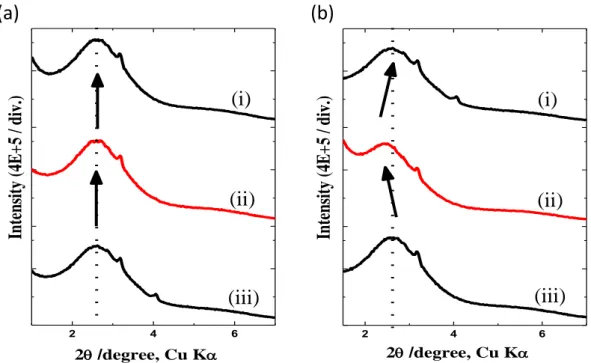
3.5.4 Interlayer expansion due to solvent percolation………..58
3.6 Conclusion……...……… 59
3.7 References……… 65
4. Activation energy of C3F-Azo-C6H in various microenvironments………. 68
4.1 Introduction……….. 68
4.2 Experimental……… 69
4.3 Principle ………. 70
4.4 Results and discussion………. 71
4.4.1 Activation energy of C3F-Azo-C6H in ethanol……….. 71
4.4.2 Activation energy of C3F-Azo-C6H in water……….. 74
4.4.3 Activation energy of C3F-Azo-C6H/Clay hybrid in benzene……. 77
xii
4.6 References……… 85
5. Laser flash photolysis of C3F-Azo-C6H in various microenvironments …. 87 5.1 Introduction……….. 87
5.2 Experimental……… 88
5.3 Results and discussion………. 89
5.3.1 Monomeric State - C3F-Azo-C6H/Ethanol…..……….. 89
5.3.2 Micellar State - C3F-Azo-C6H/Water…….……….. 90
5.3.3 Dispersed state - C3F-Azo-C6H/Clay hybrid in benzene…..……. 91
5.3.4 Dispersed state - C3F-Azo-C6H/Clay hybrid in hexane...….……. 92
5.3.5 Nanosecond laser studies in film state………..….……. 94
5.3.5.1 Film state - C3F-Azo-C6H/SSA……… 94
5.3.5.2 Laser power dependency - C3F-Azo-C6H/SSA…..….…..96
5.3.5.3 Lifetime analysis - C3F-Azo-C6H/SSA..……….. 100
5.3.5.4 Film state - C3H-Azo-C6H/SSA………..……….……… 101
5.3.5.5 Laser power dependency - C3H-Azo-C6H/SSA………... 102
5.3.5.6 Lifetime analysis - C3H-Azo-C6H/SSA……….……… 104
5.3.5.7 Comparison C3F-Azo-C6H and C3H-Azo-C6H...………..106
5.3.6 Laser studies in swelled state of hybrid sample…….………. 108
5.3.6.1 Decay Kinetic Analysis………....108
5.3.6.2 Lifetime analysis………..………..………...109
5.4 Conclusion……….……...110
5.5 References……….114
xiii
6. Activation energy of C3F-Azo-C6H in various microenvironments………. 117
6.1 Introduction……….. 117
6.2 Experimental……… 117
6.3 Results and discussion………. 118
6.3.1 Micro-environment dependent fluorescence switching of Rhodamine B………...118
6.3.1.1 Fluorescence decay of RhB in solution state……….. 119
6.3.1.2 Fluorescence decay of RhB in film state…………..…….. 121
6.3.2 Molecular heat dependent luminescence switching of [Ru(bpy)
3]
2+………. 132
6.3.2.1 Fluorescence decay of Ru(bpy)
32+in solution and film state……….. 134
6.4 Conclusion………... 145
6.5 References……… 146
7. Conclusion……….……… 148
xiv
SAM Self-assembled Monolayer
STM Scanning Tunneling Microscopy
LCE Liquid Crystal Elastomer
LC Liquid Crystal
RB Rose Bengal
SSA Sumecton SA
CEC Cation Exchange Capacity
XRD X Ray Diffraction
C3F-Azo-C6H Polyfluorinated Cationic surfactant containing azobenzene moiety
C3H-Azo-C6H Non-polyfluorinated Cationic surfactant containing azobenzene moiety
QY Quantum Yield
TG Thermo Gravimetry
DTA Differential Thermal Analysis
LL Loading Level
DSC Differential Scanning Calorimetry
N
AAvogadro number of molecules
AAS Adsorbed Amount of Surfactant
PSS Photo Stationary State
CMC Critical Micellar Concentration
AE Activation Energy
xv
RhB Rhodamine B
NMR Nuclear Magnetic Resonance
TEM Transmission Electron Microscopy
VCR Volume Changing Ratio
VE Vibrational Energy
xvi
Figure 1.1 Microenvironments for chemical reaction 01 Figure 1.2 Novel chemical reaction filed: inorganic-organic hybrids 02 Figure 1.3 Energy diagrams for the dye dimers of H- and J-type types
according to molecular exciton theory 03
Figure 1.4 Structures of micelle and vesicle 06
Figure 1.5 The reversible cyclization reaction of diarylethene molecule 08 Figure 1.6 Schematic representation of switching of terminally
thiolated azobiphenyl molecules on gold substrate 09 Figure 1.7 A light-driven plastic motor with the LCE laminated film 10 Figure 1.8 Structure of novel Polyfluorinated surfactants and
hydrocarbon surfactant 11
Figure 1.9 Micellar structure of (a) CnF-S (b) CnH-S 11 Figure 1.10 Microscopic structure of the polyfluorinated micelle 12 Figure 1.11 Various supramolecular assemblies formed by
C3F-Azo-C6H 14
Figure 1.12 Schematic representation of the photoisomerization
within niobate nanosheet 15
Figure 1.13 Morphology change in the cross-cut film edge of the layered hybrid film caused by photoirradiation:
topographic images of the hybrid film 16 Figure 1.14 3-Dimensional morphology change of the
layered hybrid film 17
xvii
Figure 2.1 Reaction scheme for the synthesis of C3F-Azo-C6H 23 Figure 2.2 Crystal structure of (a) an inorganic layered clay mineral,
Sumecton SA (SSA) and chemical structures of (b) polyfluorinated cationic surfactant (C3F-azo-C6H)
and (c) alkylated cationic surfactant (C3H-azo-C6H 24 Figure 2.3
1H NMR spectrum of C3F-Azo-C6H in
deuteriated chloroform 25
Figure 2.4 FAB-MS spectrum of C3F-Azo-C6H 26
Figure 2.5 Calculation of molar absorptivity plot of C3F-Azo-C6H
in ethanol in all trans state 27
Figure 2.6 Preparation of Clay/C3F-Azo-C6H hybrid 28 Figure 2.7 TG/DTA analyses of clay/C3F-Azo-C6H hybrids of
different loading levels 30
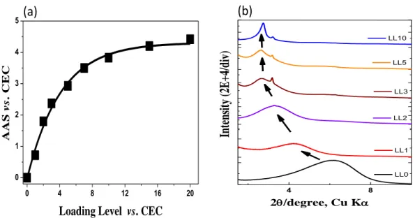
Figure 2.8 Adsorbed amounts of C3F-Azo-C6H (versus CEC) against the loading levels and X-ray diffraction pattern of the
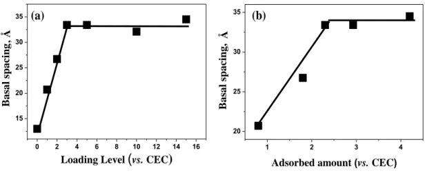
C3F-Azo-C6H/SSA hybrids film at each loading level 32 Figure 2.9 Plot of interlayer spacing vs. loading level amount of
surfactant normalized to CEC and plot of interlayer spacing vs adsorbed amount of surfactant normalized to CEC 33 Figure 2.10 Photoreaction of clay/C3F-azo-C6H hybrid in film state and
schematic representation showing the interlayer expansion in clay/C3F-Azo-C6H hybrid up on prolonged ultraviolet
light irradiation 36
Figure 3.1 Absorption spectrum changes of C3F-azo-C6H in
xviii
ethanol and micelle 45
Figure 3.3 Absorption spectrum changes of C3F-azo-C6H/Clay
hybrid in benzene and film 48
Figure 3.4 Calculation of quantum efficiencies of C3F-azo-C6H/SSA
hybrid in benzene and film 49
Figure 3.5 Absorption spectrum changes and quantum efficiency calculations of C3F-azo-C6H/Clay hybrid in film state
swelled with hexane 51
Figure 3.6 Thermal cis to trans isomerization of clay/C3F-Azo-C6H
hybrid in film state at 30
0C 53
Figure 3.7 C3F-Azo-C6H in trans and cis form 54
Figure 3.8
1H NMR analysis of C3F-Azo-C6H in ethanol-d
655 Figure 3.9
1H NMR analysis of C3F-Azo-C6H in D
2O 57 Figure 3.10 The XRD patterns of C3F-Azo-C6H/SSA hybrid film
swelled with benzene and n-hexane 58
Figure 3.11 Graphical representation of reactivity of C3F-Azo-C6H
in various micro-environments 61
Figure 3.12 Schematic illustration of energy state diagrams for photo-isomerization of unsubstituted azobenzene and
C3F-Azo-C6H in various microenvironment 62 Figure 4.1 Hierarchical photoisomerization reactivity of
C3F-Azo-C6H 69
xix
Figure 4.2 Thermal isomerization of C3F-Azo-C6H/ethanol at
various temperature 73
Figure 4.3 Plot of inverse of temperature vs. logarithm of rate constant for calculation of activation
energy for C3F-Azo-C6H/ethanol 74
Figure 4.4 Thermal isomerization of C3F-Azo-C6H/water
at various temperature 76
Figure 4.5 Plot of inverse of temperature vs. logarithm of rate constant for calculation of activation
energy for C3F-Azo-C6H/water 77
Figure 4.6 Thermal isomerization of C3F-Azo-C6H/SSA hybrid in
benzene dispersion at various temperature 79 Figure 4.7 Plot of inverse of temperature vs. logarithm
of rate constant for calculation of activation energy for C3F-Azo-C6H/SSA hybrid in
benzene dispersion 80
Figure 4.8 Thermal isomerization of C3F-Azo-C6H/SSA hybrid in
film state 82
Figure 4.9 Plot of inverse of temperature vs. logarithm of rate constant for calculation of activation
energy for C3F-Azo-C6H/SSA hybrid in film state 83 Figure 4.10 Possible pathway of cis to trans isomerization on the
basis of activation energy measurements 84
Figure 5.1 Optical alignment for the direct excitation of XeCl laser
xx
C3F-Azo-C6H in ethanol 90
Figure 5.3 Transient absorption spectrum and decay profile of
C3F-Azo-C6H in water 91
Figure 5.4 Transient absorption spectrum and decay profile of
C3F-Azo-C6H/SSA hybrid in benzene 92
Figure 5.5 Transient absorption spectrum and decay profile of
C3F-Azo-C6H/SSA hybrid in hexane 93
Figure 5.6 Transient absorption spectra and decay kinetics monitored at 365 nm of C3F-Azo-C6H/SSA hybrid in film state
with LP1 96
Figure 5.7 Decay kinetics monitored at 365 nm of C3F-Azo-C6H/SSA
hybrid in film state with LP1 96
Figure 5.8 Transient absorption spectra and decay kinetics of
C3F-Azo-C6H/clay hybrid in film state with LP2 and LP4 97 Figure 5.9 Decay curves of C3F-Azo-C6H/clay hybrid in film state
monitored at 455 nm with LP2 and LP4 98
Figure 5.10 Laser power dependency on decay curves of
C3F-Azo-C6H/SSA 99
Figure 5.11 Lifetime analysis of intermediates formed in
C3F-Azo-C6H/Clay hybrid 100
Figure 5.12 Decay kinetics of C3H-Azo-C6H/clay hybrid in film
monitored with LP1 102
xxi
Figure 5.13 Decay kinetics of C3H-Azo-C6H/clay hybrid in film
monitored with LP2 103
Figure 5.14 Laser power dependency on decay curves of
C3H-Azo-C6H/SSA 104
Figure 5.15 Lifetime analysis of intermediates formed in
C3H-Azo-C6H/Clay hybrid 105
Figure 5.16 Microenvironment dependency (LP4) on decay curves
C3F-Azo-C6H and C3H-Azo-C6H/SSA in each time scale 107 Figure 5.17 Decay kinetics of C3F-Azo-C6H/clay hybrid in film state
swelled in hexane 108
Figure 5.18 Lifetime analysis of intermediates formed in
C3F-Azo-C6H/Clay hybrid swelled with hexane 110 Figure 5.19 Mechanistic pathways showing the isomerization of
azobenzene moiety 111
Figure 5.20 Pathway showing the cooling down of excess energy
via multistep process in C3F-Azo-C6H/SSA hybrid film 113 Figure 5.21 Pathway showing the cooling down of excess energy
via multistep process in C3H-Azo-C6H/SSA hybrid film 114 Figure 5.22 Rate of heat dissipation in clay hybrids with C3F- and C3H. 114 Figure 6.1 Co-intercalation of Rhodamine B with surfactant/SSA
and schematic representation of energy level diagram 118 Figure 6.2 Absorption spectra of RhB in (a) C3F-Azo-C6H in ethanol
and water (c) water and ethanol. Emission spectra of RhB
in (b) C3F-Azo-C6H in ethanol and water
xxii
(b) C3F-Azo-C6H in ethanol and water switching
between all trans, cis rich and trans rich forms 121 Figure 6.4 XRD pattern of different loading levels of co-intercalated
RhB with (a) SSA – (i) 10% RhB (ii) 6% RhB (iii) 1% RhB (b) C3F-Azo-C6H/SSA hybrid (i) 10% RhB (ii) 6% RhB
(iii) 1% RhB 122
Figure 6.5 (a) Absorption spectra of co-intercalated RhB in
C3F-Azo-C6H/SSA hybrid and C3H-Azo-C6H/SSA hybrid in film state below 1%.(vs. CEC) (b) Emission spectra of co-intercalated RhB in C3F-Azo-C6H/SSA hybrid and
C3H-Azo-C6H/SSA hybrid in film state below 1% (vs. CEC) 123 Figure 6.6 Fluorescence decay of RhB in (a) SSA with intercalation
amount of 1%, 6%, 10% (vs. CEC) (b) C3F-Azo-C6H/SSA with intercalation amount of 1% (vs. CEC) switching
between all trans, cis rich, trans rich forms 124 Figure 6.7 Fluorescence decay of RhB in (a) C3F-Azo-C6H/SSA
(b) C3H-Azo-C6H/SSA, with intercalation amount of 1%
(vs. CEC) switching between trans, cis rich and
trans rich forms 125
Figure 6.8 Lifetime and pre-exponential factor switching between
isomer rich states of (a) and (c) 1% RhB/SSA/C3F-Azo-C6H
xxiii
and (b) and (d) 1% RhB/SSA/C3H-Azo-C6H 128
Figure 6.9 Temperature dependence of RhB 130
Figure 6.10 Calculation of temperature elevation using RhB dye system 130 Figure 6.11 Orientation of dye molecule within nano-layered
micro-environment 132
Figure 6.12 Co-intercalation of Ru(bpy)
32+with surfactant/SSA and
schematic representation of energy level diagram 133 Figure 6.13 Absorption spectra of Ru(bpy)
32+in (a) C3F-Azo-C6H in ethanol and water (b) water and ethanol. Emission spectra of RhB in (c) C3F-Azo-C6H in ethanol and water (d) water
and ethanol 135
Figure 6.14 Fluorescence decay of Ru(bpy)
32+in (a) water, ethanol, C3F-Azo-C6H in water and ethanol and water (b) with 1%
and 2% (vs. CEC) with SSA 135
Figure 6.15 XRD pattern of different loading levels of co-intercalated Ru(bpy)
32+with (i) 2% Ru(bpy)
32+/SSA (ii) 1% Ru(bpy)
32+/ SSA (iii) 100% Ru(bpy)
32+/SSA (iv) naked clay 137 Figure 6.16 (a) Absorption and (b) emission spectra of co-intercalated
Ru(bpy)
32+with (i) C3F-Azo-C6H/SSA hybrid film state
below 1 %.( vs. CEC) (ii) SSA below 1 % ( vs. CEC) 138 Figure 6.17 Fluorescence decay of Ru(bpy)
32+in (a) C3F-Azo-C6H/SSA
(b) C3H-Azo-C6H/SSA, with intercalation amount of 1%
( vs. CEC) switching between all trans, cis rich and trans rich
forms 139
xxiv
Azo-C6H and (b) and (d) 1% RhB/SSA/C3H-Azo-C6H 139 Figure 6.19 Schematic representation of energy levels in Ru(bpy)
32+140 Figure 6.20 Compilation of luminescence lifetimes as a function of
temperature for [Ru(bpy)3]
2+143
Figure 6.21 Boltzmann distribution equation for the calculation of emission lifetime dependent temperature of dye molecule
system 143
Figure 6.22 Schematic representation of energy levels in Ru(bpy)
32+144
xxv
List of Tables
Table 2.1 Molar extinction co-efficient of cis and trans isomer
C3F-Azo-C6H and C3H-Azo-C6H………27 Table 2.2 Adsorbed amount and occupation area of surfactant on clay with
various loading levels ... 31 Table 2.3 Absorption spectral characteristics of C3F-Azo-C6H in
various microenvironments... 33 Table 3.1 Quantum efficiency for C3F-azo-C6H in monomeric state... 46 Table 3.2 Quantum efficiency for C3F-azo-C6H in micellar state…... 47 Table 3.3 Quantum efficiency for C3F-azo-C6H/clay hybrid in dispersed
state………... 49 Table 3.4 Quantum efficiency for C3F-azo-C6H/clay hybrid in film state... 50 Table 3.5 Quantum efficiency for C3H-azo-C6H/clay hybrid in film state... 50 Table 3.6 Quantum efficiency for C3F-azo-C6H/clay hybrid in swelled state... 52 Table 4.1 Summary of activation energy calculated in each microenvironment... 83 Table 5.1 Lifetime of intermediates formed in C3F-Azo-C6H/SSA hybrid
with LP4……….100 Table 5.2 Lifetime of intermediates formed in C3H-Azo-C6H/SSA hybrid
with LP4……….105 Table 5.3 Lifetime of intermediates formed in C3F-Azo-C6H/SSA hybrid
swelled in hexane with LP4……..……….109
Table 6.1 Fluorescence decay lifetime of RhB in solution state………121
Table 6.2 Fluorescence decay lifetime of RhB/SSA in film state...126
xxvi
Table 6.4 Fluorescence decay lifetime of RhB/SSA/C3H-Azo-C6H
in film state……… 127 Table 6.5 Calculation of elevation of temperature in RhB/SS/C3F-Azo-C6H
system... 131 Table 6.6 Fluorescence decay lifetime of Ru(bpy)
32+in solution state... 136 Table 6.7 Fluorescence decay lifetime of Ru(bpy)
32+/C3F-Azo-C6H/SSA
in film state... 141 Table 6.8 Fluorescence decay lifetime of Ru(bpy)
32+/C3H-Azo-C6H/SSA
in film state………... 141 Table 6.9 Constant values reported for the calculation fluorescence lifetime dependent
temperature………... 143
1
Chapter 1.
General Introduction
1.1 Microenvironments for chemical reaction
When we go on from solid to solution and then to vacuum state, degree of freedom for chemical reactions increases. In nature and man-made systems there are numerous microenvironments whose degree of freedom comes in between solid and solution states.
Out of which some of the important microenvironments whom our group mainly focusing are mesoporous silica, niobate nanosheets and nanoscrolls, different types of
Figure 1.1 Various well known microenvironments providing unique chemical reactions (a) mesoporous silica (b) hexaniobate nanosheet (c) hexaniobate nanoscroll (d) vesicles (e) clay nanosheet (f) micelle.
clay mineral nanosheets, micelles, vesicles, etc.
1-11They are widely utilized in and as
Sumecton SA
[(Si7.20Al0.80)(Mg5.97Al0.03)O20(OH)4]-0.77・(Na0.49Mg0.14)+0.77
Surface Area: 750 m2g-1 CEC: 0.997 eq. g-1
20 nm
Ads orption of Water
Layer Thicknes s
= 0.96 nm
~10 nm
(c)
(e)
(a) (b)
(d) (f)
2
specific site for reaction field such as adsorbents, catalysis, artificial membranes, drug delivery, sensors, synthetic biological systems, etc.
12-19We have been extensively exploring the possibility of utilizing these systems for the efficient energy production by varying the incorporating organic molecules.
1.2 Inorganic-organic hybrid compounds
Organic-inorganic hybrid composites have caught attention not only from the perspective of academic research as a creative and alternative pathway for the preparation of various compounds, but also for the production of materials having tremendous industrial impact on application level as well. The scope of inorganic-organic hybrids is widely explored for unique chemical reactions such as electron transport, self-assembly, molecular orientation, catalysis, sorption of metals, anions and organics, reactors for polymerization, fixation of biologically active species, solar cells, sensors, photonic applications, thin film field effect transistors and so on.
2-4Various methods for their preparation include copolymerization, sol-gel reaction, and organic functionalization,
Figure 1.2 Novel chemical reaction filed: inorganic-organic hybrids.
intercalation, bio-synthesis, etc.
5They can be classified into two distinct sections. Class
CHAPTER 1. INTRODUCTION
3
Ι involves the compounds having weak intermolecular interaction between organic and inorganic part and class ΙΙ are those with formed by rather strong chemical bonds. The highlight of this kind of hybrid material is the enhanced properties obtained in small volume and most importantly they are not just physical mixtures but a composite with united properties of both organic and inorganic material.
6A wide variety of host materials have been reported so far. The expandable and two-dimensional wide-layered structure makes the inorganic layered compounds potential candidate as a host material. Clay minerals, layered double hydroxide and layered semiconductors are used as typical layered host materials.
7-9From the view point of a photochemist, curious thing happening in the interlayer is the change in photophysical properties of the organic molecular assembly incorporated within the host material. Molecular aggregation happens by a mechanism of loss of entropy of solvent system. Hydrophobic interaction of molecules causes the decrease in the translational and rotational degrees of freedom of solvent system as a result van der waals force of attraction is diminished.
Figure 1.3 Energy graphs for the dye dimers of H- and J-type types according to molecular exciton theory.
10ES
GS
"Head to Tail" " Card Pack"
J aggregate
Monomer H aggregate
J M H
Line of centers
a
a 0
o54
o90
o4
The large sift in the absorption spectra of aggregates compared to monomeric form is explained on the basis of molecular exciton model. Excited state splits into degenerate states by the electrostatic interaction between the transition moments of molecule.
Depending on the arrangements, there are two possible states, J-type and H-type. Both are possible ideal systems where real assemblies could be a mixture. J-type aggregates are head to tail arrangements in which antiparallel interactions of transition moments result in the highest energy level and symmetry allowed transition to lowest energy state only possible. In the case of H- type aggregates molecules are aligned in a card packed or sandwich like and transition moments are parallel oriented allowing the transition to symmetrically favourable highest energy state which causes blue shift (hypsochromic shift) in the absorption, emission, reflectance or transmittance spectrum (towards shorter wavelength) and vice versa for former aggregates where red shift (bathochromic) occurs.
11There are wide varieties of layered inorganic host materials have been explored viz.,
anionic and cationic clay minerals, layered niobates, layered double hydroxides, etc.
12-16Out of which Clay minerals are a class of compounds containing layered particles
composed of many layers that have remarkable ability to adsorb and intercalate cationic
or neutral molecules. Sum of variable and permanent charges results in a negative
surface charge on individual layers. They contain octahedral and tetrahedral sheets
which isomorphically substituted central atoms which causes the permanent negative
charges and presence of hydroxyl groups explain its acid/base properties. The effect of
charge density on the properties of inorganic cations is negligible and distances between
opposite charges are as short as possible dictated by the factors like cationic size and
CHAPTER 1. INTRODUCTION
5
shape, hydration energy, osmotic potential, etc. But surface charge density significantly affects the molecular arrangement, orientation and its properties of intercalated cationic organic surfactants. Distribution of negative charge is determined by alkylammonium method has been reported previously. This is crucial factor as the selection of mineral with characteristic layer charge value may be useful in preparing hybrid with specific properties.
11Clay minerals are fundamentally built of tetrahedral silicate and octahedral hydroxide sheets in various compositions. On the basis of ratio of these compositions we can classify them mainly into four categories.
5, 17-19a. Smectite group: - Clay mineral with 2:1 ratio of tetrahedral sheet and octahedral sheet with latter is sandwiched in between two tetrahedral sheets. They include montmorillonite, vermiculite, nontronite, pyrophyllite, sauconite, saponite, etc with a general formula (Ca, Na, H) (Al, Mg, Fe, Zn)
2(Si, Al)
4O
10(OH)
2. xH
2O. Sumecton SA, talc comes under this category. Variable amount of water is present inside interlayer.
b. Kaolinite group: - Include dicktite, nacrite, halloysite and kaolinite having gegeral formula of Al
2Si
2O
5OH
4. They are 1:1 minerals with tetrahedral and octahedral sheets are arranged in pair fashion.
c. Illite group: - They include muscovite and illite with a general formula (K, H) Al
2(Si, Al)
4O
10(OH)
2. xH
2O. They are also called as clay-mica groups and composed of two inward pointing tetragonal sheets.
d. Chlorite group: - There are numerous minerals come under this category. Some of
them are amesite, baileychlore, chamosite, clinochlore, cookeite, daphnite, nimite,
odinite, penninite, pannanite, sudoite, etc. General formula is (Al, Fe, Li, Mg, Mn, Ni,
6
Zn, Cr)
4-6Y
4)
10(OH, O)
8. This class has no industrial uses.
Clay minerals have got substantial interest in perspective of unique microenvironmental reaction like in catalysts, molecular recognition, stereospecific control of intercalants, etc. Clay-surfactant hybrids are employed in a wide variety of industrial and scientific applications, such as adsorbents for organic pollutants, catalysts, rheological control agents, reinforcing fillers for plastics, electric materials and mesoporous materials.
20-23The structure and orientation of surfactants largely dictates the applications of these clay hybrids.
24Surfactants are amphiphilic molecules having hydrophobic and hydrophilic part in the same molecule. At lower concentration molecules compete to situate in the gas-liquid phase and rest are remained in solution. But as the concentration increases entropy is decreased molecular aggregation occurs forming stable micelles. Physical properties of molecules such as optical properties, dielectric constant, surface tension etc were largely changed here. At very high concentration molecular double layer is formed with minimal hydrophobic interaction. In this case hydrophilic parts are tending to orient towards solvent.
1, 12, 25, 26Figure 1.4 Structures of micelle and vesicle.
27CHAPTER 1. INTRODUCTION
7 1.3 Photomechanical systems
5, 6, 28It’s always been great dream of chemists to realize molecular machines which operates by some external forces like temperature, pressure or by supplying energy in terms of photons or electrons. In view of photochemist it would be highly interesting to have devices that can convert light energy into mechanical energy. Indeed it is very clear that we don’t have much efficient artificial molecular machines or photomechanical systems that would be comparable to that of macroscopic one. By utilizing photonic energy combined with supramolecular assisted covalent synthesis could be a powerful tool in designing molecular machines. While mimicking natural system man-made tools may be working on the following categories, viz. chemical rotors, chemically and electronically induced rearrangements, chemically, photochemically and electrochemically controllable motions in interlocked molecules (catenanes and rotaxanes).
1. A rotory motor – F1-ATPase, Proton channels lie at the interface between a and c subunits. When proton flow occurs there is torque generates which is transmitted to F1 where ATP is released.
2. Linear motor proteins, Enzymes such as myosin, kinesin, dynein and their relatives are linear motors which convert ATP to mechanical energy.
Artificial molecular machines – Supramolecular chemistry is powerful tool for
designing well organized functioning molecular devices which are able to interpret,
store, process as in natural systems. Rotaxanes and catenanes are classified into the
above category which are prepared by template synthesis and can act as molecular
machines. By developing these type of molecular machines, not only of particular
interest of basic science but can also serve as an important fertilizer for nanoscience and
8 nanotechnology.
Photomechanical systems based on diarylethene have been extensively studied by Prof.
Irie and co-workers in the recent past.
29-32The surface morphology of single crystal of diarylethene is found to change reversibly upon UV and visible irradiation. Very interestingly the macroscopic crystal found to follow the microscopic phenomenon following photoirradiation. Compared to azobenzene based system diarylethene and derivatives are thermally irreversible and response time is too less. Bending rate is measured to be completed in 25 microseconds and such fast timescales can be comparable to that of piezoelectric devices. The ring opening and closing in diarylethenes causes intermolecular interaction of stacked molecules which then constitute to macroscopic bending. These class of compounds are having wide variety of applications such as memory devices, molecular switches, selective deposition of metal atoms, photo-controlled surface wettability, etc.
Figure 1.5 The reversible cyclization reaction of diarylethene molecule from open-ring
isomer to the closed-ring isomer (a) Tip displacement of the crystal during the
reversible bending (b) Photographs of the crystal in the 1st, 100th, and 250th cycles of
the reversible bending.
30CHAPTER 1. INTRODUCTION
9
Photomechanical switching of azobenzene and its derivatives on gold surface have been widely investigated. Prof. Samori and co-workers reported imaging of such photoresponsive switching on gold surface by scanning tunneling microscopy.
33Most promisingly they have found the switching of entire 2D lattice happening due to a co-operative phenomenon among the neighbouring molecules. Here fully conjugated terminally thiolated azobiphenyl oligomer is densely chemisorbed on Au (ІІІ) surface.
Self-assembled Monolayer’s (SAMs) were found to have high order and this assembly giving rise to high cis to trans reaction and this kind of system renders to unique platform form for molecular devices for nanomechanical and nanoelectronic devices.
Figure 1.6 Schematic representation of switching of terminally thiolated azobiphenyl molecules on gold substrate.
33Very similar work on SAMs of azobenzene derivatives on gold nano-surface also been reported by Prof. Li-Jun Wan and workers where rigidity and steric effect of self – assembly leading to special features unlike in solution and solid state.
Liquid-crystalline elastomers (LCEs) are a class of compounds having both properties
of liquid crystals (LCs) and elastomers showing high amount of deformation in
10
structure by light irradiation and many photomechanical systems have been reported so far. Prof. Ikeda and co-workers reported the macroscopic photo-induced rolling of azobenzene based LCEs at room temperature.
34This kind of motion in single layer has been reported for the first time. Since molecules causing this photoinduced motion only on surface, a hybrid film of LCEs coated on polyethylene is prepared and internal stress generated is measured with photoirradiation with external load. Mechanical stress was generated upon light irradiation and this mechanical stress was found to upsurge with increase in light intensity. Breakage of film occurred at very high intensity of light.
Ultimately a light driven motor was designed and photomechanical movement is realized on photoirradiation. They have successfully developed new light-driven plastic motor with LCE films and their composite materials, which can convert light energy directly into mechanical work without the aid of any external energy.
Figure 1.7 A light-driven plastic motor with the LCE laminated film.
341.4 Research background
CHAPTER 1. INTRODUCTION
11
Our group has been doing keen research on photochemistry in the micro-environment utilizing photoresponsive hybrid materials.
13, 35-37We have deeply investigated the polyfluorinated surfactants, (C
nF-S) having the unique property of high oxidation resistance, attached with one or two long alkyl chain along with alkylated derivative (C
nH-S), where fluorine atoms are replaced by hydrogen.
1, 25, 26Figure 1.8 Structure of novel Polyfluorinated surfactants and hydrocarbon surfactant.
The C
nF-S series of compounds found to form micelles when dispersed in water. The C
nH-S compounds also found to form micelles with bending of alkyl head. Molecular assemblies formed by these two surfactants were shown to be different and the root cause assigned to be the presence of polyfluorinated head in C
nF-S.
Figure 1.9 Micellar structure of (a) CnF-S (b) CnH-S.
The oxidative degradation of these systems was studied by using Fenton’s reagent and
12
Rose Bengal (RB). Compared to C
nH-S series, C
nF-S series showed high resistance towards oxidation.
Figure 1.10 Microscopic structure of the polyfluorinated micelle.
With addition of Mn
2+, probing with
19F and
1H NMR, detailed structure of micelle was determined and it’s given in fig. 1.11. Surfactant forms reverse micelle in toluene/water system and vesicles formation also characterized by TEM and NMR.
Hybrid compounds of polyfluorinated and non-polyfluorinated surfactants with that of Sumecton SA were prepared. Surfactants intercalate into the interlayer space of negatively charged clay nanosheets. As the amount of surfactants were increased up to a saturated condition of 4.3 vs CEC for C3F-S and for C3H-S the saturated condition was found to be two times that of CEC. The basal spacing of clay was found to increase upto 40 Å even after loading level of 2, from 13 Å for C3F-S. But for C3H-S interlayer expansion was found to be 20 Å. This saturated condition happened from loading level 3. There is a linear relationship with Interlayer expansion and polyfluoroalkyl chain length.
Azobenzene analogues of polyfluoroalkylated surfactants were also deeply examined in
CHAPTER 1. INTRODUCTION
13
various micro-environmental aspects. As similar to biological systems, light can be utilized in photoresponsive materials not only as an energy source but also as a trigger for the reversible control of the physical and chemical properties of photochromic molecules. Even though we are not yet successful in reconstructing the biological photoresponsive systems, it is worthwhile mimicking the processes and applying them to the photoresponsive materials, so that the physical and chemical properties can be changed reversibly by photoirradiation.
29, 38What make these azobenzene and its derivatives special to be incorporated as guest ions into the interlayer spacing of hybrid material?
1. With large substituents at the phenyl rings, when it isomerizes form trans to more bulky cis one, capable of converting light energy to mechanical energy and can be extended to macroscopic scale.
2. Difference in the dipolemoment i.e. when trans with oppositely arranged lone pair of electrons are transformed to cis, there is a significant increase in the dipole moment occurs.
18, 39The complexation of organic photoresponsive material like azobenzene as such or its derivative possessing more exciting properties, with inorganic compounds to obtain hybrid material having combined (or even enhanced) property is having great significance.
Many azobenzene containing clay hybrids were reported with poor reversibility.
40-42We synthesized polyfluorinated azobenzene surfactants (CnF-Azo-CxH) which forms
well-organized bilayer structure within interlayer space having enhanced transparency
and photoreversibilty. Various derivatives are prepared by changing the alkyl and
polyfluroalkyl chains. It forms various supramolecular assemblies like micelle, vesicle,
14
lamellars, hybrids with niobate nanosheet, niobate nanoscroll, clay, mesoporous silica, etc.
Figure 1.11 Various supramolecular assemblies formed by C3F-Azo-C6H.
C3F-Azo-C6H also found to form nanosheet and nanoscroll hybrids with potassium hexaniobate. Compared to clay nanosheets (size of several tens of nm) niobate nanosheets have got relatively much larger size (1 μm) with two types of interlayer.
Potassium hexaniobate is prepared by calcining Nb
2O5 and K
2CO
3at 1100
0C for 10
hours. The intercalation of C3F-Azo-C6H with K
4Nb
6O
17could not be carried by a
direct reaction. Methylviologen- K
4Nb
6O
17intercalated compounds were used as the
precursor by intercalating into layer І. The interlayer expanded to 53.5 Å. From
TG/DTA analysis surfactant adsorbed to the nanosheet at level 2.5 vs CEC. A bilayered
structure of C3F-Azo-C6H were formed within interlayer and found to show reversible
isomerization as observed UV-visible spectroscopy by altering UV-visible
CHAPTER 1. INTRODUCTION
15
photoirradiation. XRD patterns of hybrid films were observed in each isomer state produced by UV and visible irradiation. The interlayer distance decreased when the hybrid is isomerized from trans form to cis form. The d-spacing (020) of hybrid shrunk and expanded repeatedly. Here the most interesting point is why interlayer is shrunk upon cis formation? The tilt angle was calculated to be 43
0with surfactants are in a standing mode and upon photoisomerization of cis molecules were formed which causes decrease in interlayer distance due to crowding of surfactant molecules within niobate nanosheets. The diagrammatic representation is shown in fig. 1.12.
35Figure 1.12 Schematic representation of the photoisomerization within niobate nanosheet.
Surprisingly, AFM analysis showed a reversible morphological change of hybrid film.
This kind of giant morphological change of hybrid material was observed by cutting in
cross section and due to isomerization, sliding of nanosheets were happening within
interlayer three dimensionally.
35, 36This kind of large sliding by supramolecular
assembling consisting of photoresponsive nanosheet hybrid was totally different from
morphology changes induced in polymer and liquid crystal films. The horizontal and
16
vertical changes were shown in figure 1.13 and 1.14. The horizontal motion in our system occurs by sliding of nanosheets over bilayered surfactants are unique and this kind of phenomenon can be compared to that of contraction and expansion of muscle tissue where motion happens by the expense of stored energy in the form of ATP.
Reversible photoinduced motion witnessed in clay/C3F-Azo-C6H hybrid as well and the details will be discussed in detail later on.
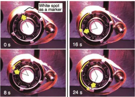
Figure 1.13 Morphology change in the cross-cut film edge of the layered hybrid film caused by photoirradiation: topographic images of the hybrid film (a) before and after (b and d) UV light irradiation (368 nm for 20 min) and (c and e) visible light irradiation (463 nm for 2 min), respectively.
360 Height / nm 550 0 Height / nm 550 UV
Light
Vis.
Light UV
Light
0 Height / nm 550
3 µm 3 µm 3 µm
0 Height / nm550 0 Height / nm 550 Vis.
Light
Nano composite
Glass substrate
a b c
d e
3 µm 3 µm
CHAPTER 1. INTRODUCTION
17
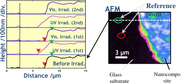
Figure 1.14 3-Dimensional morphology change of the layered hybrid film. (a) Height profiles of the hybrid film cross section. (b) Relative distance from the reference point to the film edge. (c) Film thickness at a point at a constant distance from the reference point.
36We speculate that cooperative phenomenon should be giving rise to the morphological change and interlayer expansion and deep investigation on the microenvironments would surely give us a deeper insight into the nano-mechanics of hybrid described above. For that we must have a detailed idea about the following aspects which will ultimately help us to explore the idea of producing very efficient photomechanical system for real world applications.
1.5 Efficient Photomechanical System
In order to understand the mechanism of sliding and to produce a much efficient photomechanical system, we have been doing keen research on the photochemical events occurring in the microenvironments, mainly by anionic clays and niobates intercalated with polyfluorinated cationic surfactants containing azobenzene moiety
0 5 10 15
Before Irrad.
UV Irrad. (1st) Vis. Irrad. (1st) Vis. Irrad. (2nd) UV Irrad. (2nd)
Distance /μm
Hei ght /1 00 n m /di v. Reference
point
AFM
3 µm
Nanocompo site Glass
substrate
18
(CnF-Azo-CmX, CnH-Azo-CmX ), by varying the perfluoroalkyl chain and alkyl chain.
In this respect, our major viewpoints are:- 1. Alignment of hybrid by external force: -
It is already reported that certain layered compounds like graphite, clay, metal oxides are having large anisotropic properties along their three crystallographic axes and these properties are very much influenced by their electron charge density, nature of intercalated ions etc. Our group have already synthesized and deeply investigated the niobate based hybrid compounds. But the interlayer expansion was not found to be uniform. The reason for this can be the random orientation while forming hybrid compounds by two step guest-guest ions exchange. It is now well-known that strong homogeneous magnetic fields can be used to achieve controlled orientation of particles in fluid suspensions and that these oriented particles can be consolidated to make composites and thin films. On applying such magnetic field we expect a uniaxial orientation i.e. crystallographic axes a, b or c of all exfoliated sheets may be stacking in one direction. Nonmagnetic compounds get aligned to magnetic field if they have a finite amount of diamagnetic anisotropy (Magnetic anisotropy is the direction dependence of a material's magnetic properties. In the absence of an applied magnetic field, a magnetically isotropic material has no preferential direction for its magnetic moment while a magnetically anisotropic material will align its moment with one of the easy axes). Hence we are proposing that with magnetically aligned hybrid material, we will be able to produce more efficient and uniform light induced back and forth sliding, expansion and contraction.
2. Detailed nature of micro-environment:-
From our previous studies, tilt angle of bilayered surfactant correlated to its initial
CHAPTER 1. INTRODUCTION
19
concentration, both in the case of clay and niobate hybrids. While preparation, stirring speed, temperature and humidity were seemed to influence the interlayer distance of the hybrid. As we have seen the interlayer space and adsorbed amount were also changed whether its polyfluoroalkylated chain or hydrocarbon chain. With change in head group (C3F- or C3H-), through which surfactant is attached on nanosheet, bending nature also differs. Adsorbed amount on surfactant were calculated by TG/DTA analysis. Further, much complicated information regarding the microenvironment still under investigation using XRD, DSC and IR.
3. Reactivity and photoisomerization behaviour within interlayer:-
Quantum yield (QY) of isomerisation refers to rate of isomerization to number of photons absorbed. Photoisomerisation of azobenzene is well studied in wide varieties.
We are focusing our attention to understand the isomerisation behaviour of C3F-Azo-C6H and C3H-Azo-C6H in solution, micelle, clay hybrid in dispersed, swelled and film state, niobate nanosheets and nanoscrolls compare among themselves under steady state and excited state.
1.6 References
1. T. Yui, S. R. Uppili, T. Shimada, D. A. Tryk, H. Yoshida and H. Inoue, Langmuir, 2002, 18, 4232-4239.
2. A. Walcarius, Chem. Mater., 2001, 13, 3351–3372.
3. H. W. T. E. Kaiser, V. Stepanenko, F. Wurthner, Angew. Chem., 2007, 119, 5637.
4. A. Stein, B. J. Melde, and and R. C. Schroden, Adv. Mater., 2000, 12, 1403–
1419.
20
5. M. Ogawa and K. Kuroda, Chem. Rev., 1995, 95, 399 - 438.
6. G. D. R. Houbertza, C. Cronauera, A. Schmitta, H. Martina, J.-U. Parkb, L.
Fröhlicha, R. Buestricha, M. Popalla, U. Streppelc, P. Dannbergc, C. Wächterc, A. Bräuer, Thin Solid Films, 2003, 442, 194 -200.
7. T. Okada, H. Sakai and M. Ogawa, Applied Clay Science, 2008, 40, 187-192.
8. R. Matsuoka, T. Yui, R. Sasai, K. Takagi and H. Inoue, Molecular Crystals and Liquid Crystals Science and Technology. Section A. Molecular Crystals and Liquid Crystals, 2000, 341, 333-338.
9. L. A. Lucia, T. Yui, R. Sasai, S. Takagi, K. Takagi, H. Yoshida, D. G. Whitten and H. Inoue, Journal of physical chemistry B, 2003, 107, 3789-3797.
10. H. R. R. M. Kasha, M. A. El-Bayoumi, Pure Appl. Chem., 1965, 11, 371.
11. J. Bujdák, Applied Clay Science, 2006, 34, 58-73.
12. T. Yui, S. Fujii, K. Matsubara, R. Sasai, H. Tachibana, H. Yoshida, K. Takagi and H. Inoue, Langmuir, 2013, 29, 10705-10712.
13. Z. Tong, S. Takagi, H. Tachibana, K. Takagi and H. Inoue, Journal of physical chemistry B, 2005, 109, 21612-21617.
14. S. Tawkaew, S. Yin and T. Sato, International Journal of Inorganic Materials, 2001, 3, 855–859.
15. Y. Okahata and A. Shimizu, Langmuir, 1989, 954-959.
16. Q. Wang and D. O'Hare, Chem. Rev., 2012, 112, 4124–4155.
17. E. R. P. a. R. E. Morris, Acc. Chem. Res., 2007, 40, 1005-1013.
18. A. R. Mermut and G. Lagaly, Clays and clay minerals, 2001, 49, 393-397.
19. P. F. Kerr, Clays and clay minerals, 1952, 1, 19-32.
20. V. R. L. Constantino, C. S. Barbosa, M. Bizeto and P. M. Dias, An. Acad. Bras.
CHAPTER 1. INTRODUCTION
21 Ci., 2000, 72, 45-49.
21. B. J. Clément Sanchez, Philippe Belleville, Michael Popall, J. Mater. Chem., 2005, 15, 3559-3592.
22. D. B. M. C. R. Kagan, C. D. Dimitrakopoulos, Science, 1999, 286, 945-947 23. E. D. Anne Dolbecq , Cédric R. Mayer , and Pierre Mialane, Chem. Rev., 2010,
110, 6009 - 6048.
24. H. He, R. L. Frost, F. Deng, J. Zhu, X. Wen and P. Yuan, Clays and Clay Minerals, 2004, 52, 350-356.
25. H. Kusaka, M. Uno, M. Krieg-Kowald, T. Ohmachi, S. Kidokoro, T. Yui, S.
Takagi and H. Inoue, Phys. Chem. Chem. Phys., 1999, 1, 3135-3140.
26. T. Yui, H. Yoshida, H. Tachibana, D. A. Tryk and H. Inoue, Langmuir, 2002, 18, 891-896.
27. www.verticallearning.org.
28. V. Balzani, A. Credi, F. M. Raymo and J. F. Stoddart, Angew. Chem. Int. Ed., 2000, 39, 3348-3391.
29. M. Irie, Pure Appl. Chem., 1990, 62, 1495-1502.
30. M. Morimoto and M. Irie, Journal of american chemical society, 2010, 132, 14172-14178.
31. M. Irie, Proceedings of the Japan Academy, Ser. B, 2010, 86, 472-483.
32. S. T. Seiya Kobatake, Hiroaki Muto, Tomoyuki Ishikawa and Masahiro Irie, Nature Letters, 2007, 446, 778-781.
33. G. Pace, V. Ferri, C. Grave, M. Elbing, C. v. Ha¨nisch, M. Zharnikov, M. Mayor, M. A. Rampi and P. Samori, PNAS, 2007, 104, 9937-9942.
34. M. Yamada, M. Kondo, J.-i. Mamiya, Y. Yu, M. Kinoshita, C. J. Barrett and T.
22
Ikeda, Angew. Chem. Int. Ed. , 2008, 47,
4986 –4988.
35. Y. Nabetani, H. Takamura, Y. Hayasaka, S. Sasamoto, Y. Tanamura, T. Shimada, D. Masui, S. Takagi, H. Tachibana, Z. Tong and H. Inoue, Nanoscale, 2013, 5, 3182-3193.
36. Y. Nabetani, H. Takamura, Y. Hayasaka, T. Shimada, S. Takagi, H. Tachibana, D.
Masui, Z. Tong and H. Inoue, journal of american chemical society, 2011, 17130-17133.
37. Z. Tong, S. Takagi, H. Tachibana, K. Takagi and H. Inoue, Chemistry Letters, 2005, 34, 608-609.
38. R. Klajn., Pure Appl. Chem., 2010, 82, 2247–2279.
39. V. Ramamurthy and K. S. Schanze, Marcel Dekker Publications, 1999, 169-209.
40. M. Ogawa and A. Ishikawa, Journal of Materials Chemistry, 1998, 8, 463.
41. M. Ogawa, M. Yamamoto and K. Kuroda, clay mierals, 2001, 36, 263.
42. M. Ogawa, T. Ishii, N. Miyamoto and K. Kuroda, Advanced materials, 2001, 13,
1107.
23
Chapter 2.
Preparation, Characterization and Preliminary Photophysical Properties of C3F-Azo-C6H and its Hybrid with Clay
2.1 Introduction
So far, our group has extensively synthesized various surfactants having a fluorocarbon chain. Among them, many studies have been carried out by changing the length of the fluorocarbon chain and replacing with hydrocarbon derivatives.
1-3Our central molecule of investigation polyfluorinated cationic surfactant, C3F-Azo-C6H, is prepared by four step synthesis starting from hexyl aniline as given in fig. 2.1.
Figure 2.1 Reaction scheme for the synthesis of C3F-Azo-C6H.
2.2 Experimental
C3F-Azo-C6H was synthesized, purified and characterized using NMR (JEOL JMN-ECS300) and FAB-MS (JEOL MSTATION JMS-700). Reagents used, ethanol (nakalai, grade 1), p-hexylaniline (TCI, EP, used without further purification), 1, 2 –
O
N N
C H3
N+ CH3
N H
O C3F7 C
H3 Br-
Fig.1 C3F-Azo-C6H
O
N N
C H3
N+ CH3
N H
O C3F7 C
H3 Br-
Fig.1 C3F-Azo-C6H
Quarterization
BrC2H4Br NaNO2,PhOH