固定式 OWC 型波力発電装置の効率に関する規則波中発電実験
村上 天元
*1,今井 康貴
*1,永田 修一
*1,高尾 学
*2Power Generation Tests in Regular Waves on Efficiency of a Fixed OWC-Type Wave Energy
Converter
Tengen MURAKAMI
*1, Yasutaka IMAI
*1, Shuichi NAGATA
*1and Manabu TAKAO
*2*1 Institute of Ocean Energy, Saga University 1, Honjo, Saga, 840-8502, Japan
*2 Department of Mechanical Engineering, National Institute of Technology, Matsue College 14-4, Nishiikuma, Matsue, Shimane, 690-8518, Japan
Abstract
A fixed oscillating water column (OWC)-type wave energy converter is composed of an air chamber, an air turbine and a generator. In this unit, the energy conversion process is divided into two main steps, the primary conversion in an air chamber and the secondary conversion in an air turbine. For the practical application of a fixed OWC-type wave energy converter, it is necessary to develop a design method which can consider the characteristics of incident wave motion, the motion of the internal free surface affected in the structure such as a curtain wall, the fluctuation of air pressure in an air chamber, and the rotation of the air turbine. On the other hand, the impulse turbine as the secondary conversion device in the OWC unit is expected to achieve high efficiency throughout a wide flow rate range. The authors conducted the 2-dimensional wave tank tests by means of the model OWC equipped with the impulse turbine to obtain the data needed to make this design method.
In past studies, the effects of air chamber length, turbine geometry and curtain wall depth on energy conversion efficiency were investigated experimentally. In this paper, the nozzle geometry of air chamber is changed, and its performance is discussed.
Key words : Wave energy, Oscillating water column, Primary conversion, Secondary conversion, Impulse turbine
1. 緒 言
振動水柱(OWC : Oscillating Water Column)型装置(Takahashi, et al., 1992)のエネルギー変換過程は,波浪の上 下動を空気の振動流に変換する一次変換と,空気の振動流をタービンの回転エネルギーに変換する二次変換
(Takao, et al., 2012)とに分けられ,研究においてもそれぞれ分けて実施されてきた.本装置は,水中における可
動部が無いため壊れにくく,沿岸固定式の場合は浮体式に比べてメンテナンスが容易となる.なお,二次変換装 置としてウエルズタービンと衝動タービン(Setoguchi, et al., 2006)があるが,本研究では高流量域で失速しない 優れた特徴を有する固定案内羽根付き衝動タービンを採用した.筆者らのこれまでの研究では,空気室奥行,案 内羽根枚数,案内羽根設定角,ロータ入口(出口)角,カーテンウォール没水深さなどの設計パラメータが一次 および二次変換効率に及ぼす影響を検討してきた.引き続き本報告では,空気室上部ノズル形状を変更した場合 のエネルギー変換効率について述べる.
原稿受付 2019年8月2日
*1 佐賀大学 海洋エネルギー研究センター(〒840-8502 佐賀県佐賀市本庄町1)
*2 松江工業高等専門学校機械工学科(〒690-8518 島根県松江市西生馬町14-4) E-mail of corresponding author: [email protected]
固定式 OWC 型波力発電装置の効率に関する規則波中発電実験 71 OTECVol. 24 (2019),71 〜 74
2. 実験装置
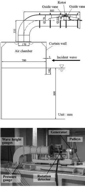
図1は実験に用いた固定式OWC型波力発電装置 の模型を示し,基準のノズル形状の場合である.模 型は,長さ18.5 m,幅0.8 m,水深0.8 mの二次元水 槽の端に設置し,もう一方の端に設置してある吸収 制御式のプランジャー型造波機によって,波高H =
0.1 m の規則波を発生させて実験を行った.空気室
の奥行Lは700 mm,カーテンウォールの厚さは5 mm,カーテンウォール没水深さは100 mmである.
タービンケーシング内径は170 mm,ハブ比は0.7で ある.なお,タービン軸端にはプーリとベルトを介 して発電機が設置されている.図2は空気室上部に 設置した圧力計および波高計の配置を示す.空気室 上部開口部は空気室中央に位置し,波高計は左舷側 3箇所と右舷側2箇所に設置した.
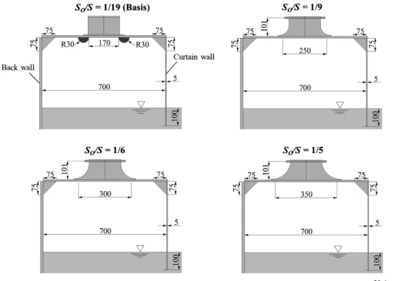
本研究では,図3に示すように,空気室上部の矩 形開口部面積SOと空気室水線面積Sとの比が基準の 1/19の場合から,1/9,1/6,1/5の3通りに変更した.
図4は衝動タービンの形状を示す.ロータの翼枚 数Zrは30枚,単段の案内羽根枚数Zgは26枚であり,
ロータの入口(出口)角は60 deg.,案内羽根設定 角は30 deg.である.
本実験では,二次変換効率2を求めるため,図5 に示すように,タービンをAC同期モータと入れ替 えて,プーリおよびベルトを含む発電機部のエネル ギー変換効率3を計測した.なお,ここでのタービ ン軸の時間平均回転速度は,上述の規則波中試験結 果と一致している.
3. 実験結果
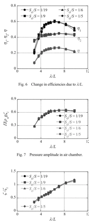
図6は実験結果であり,面積比SO/Sが1/19,1/9, 1/6,1/5 の場合の効率を示している.横軸は入射波 の波長と空気室奥行 Lとの比を表している.電気
抵抗値は3040 一定である.効率1,2,および
3は以下の式で定義される.
1 air
wave
P
P (1)
2 1
in air
P P
(2)
1 2 3 out 1
wave
P
P
(3)
Fig. 1 Model OWC with impulse turbine and generator.
Fig. 2 Positions of pressure and wave height gauges.
村上 天元,今井 康貴,永田 修一,高尾 学 72
3 out in
P
P (4)
ここで,Pair,Pwave,PoutおよびPinはそれぞれ時間 平均の空気室内空気パワー,入射波パワー,発電機 出力およびモータ入力を表し,これらのパラメータ は以下の式で定義される.
0 ( )
T air S z
P p t dt
T t (5) 1 2
wave 2 w i g
P g C W (6)
2
out V
P R (7)
0
PinT (8)
T,p,z,w,g,i,Cg,W,V,T0およびは,
波周期、空気室内圧力,空気室内5箇所平均水位,
水密度,重力加速度,入射波振幅,群速度,空気室 幅,誘起電圧,タービン出力トルクおよびタービン 角速度をそれぞれ表す.
図6に示すように,面積比SO/Sがいずれの場合も
/L = 6.3近傍で一次変換効率1のピークを示し,そ
Fig. 3 Nozzle geometry of air chamber.
Fig. 4 Configuration of rotor and guide vane.
Fig. 5 Arrangement of test devices to measure efficiency of generator, pulleys and belt.
固定式 OWC 型波力発電装置の効率に関する規則波中発電実験 73
の値は約0.6であり,面積比SO/Sが効率に及ぼす影 響は殆ど見られなかった.
次に,図7および図8は空気室内の圧力振幅およ び水位振幅を示すが,これらにおいても面積比SO/S の影響は殆ど見られなかった.
4. 結 言
本研究では,衝動タービンと発電機を装備した固 定式OWC型波力発電装置のエネルギー変換効率に 及ぼす空気室上部ノズル形状の影響を検証するため,
上部開口部面積および水線面積との比SO/Sを基準の 1/19から1/9,1/6,1/5へ変更したが,効率,空気室 内圧力振幅および水位振幅に殆ど違いは見られなか った.
謝 辞
本研究の一部は,経済産業省/三菱総合研究所受託 研究「新エネルギー等共通基盤整備促進事業」の一 環で実施された.
文 献
Takahashi, S., Nakada, H., Ohneda, H., Shikamori, M., Wave Power Conversion by a Prototype Wave Power Extracting Caisson in Sakata Port, Coastal Engineering 1992, pp.3440-3453.
Takao, M., Setoguchi, T., Air Turbines for Wave Energy Conversion, International Journal of Rotating Machinery, Vol.2012 (2012), Article ID 717398, doi:10.1155/2012/717398, 10 pages.
Setoguchi, T., Takao, M., Current Status of Self Rectifying Air Turbines for Wave Energy Conversion, Energy Conversion and Management, Vol.47 (2006), pp.2382-2396.
Fig. 6 Change in efficiencies due to/L.
Fig. 7 Pressure amplitude in air chamber.
0 0.2 0.4 0.6
0.8 SO/S = 1/19 SO/S = 1/9
SO/S = 1/6 SO/S = 1/5
0 4 8 12
1, 2, 1
2
/L
0 0.3 0.6 0.9
0 4 8 12
SO/S = 1/19 SO/S = 1/9 SO/S = 1/6 SO/S = 1/5
/ wg i
/L
0 0.5 1 1.5
0 4 8 12
SO/S = 1/19 SO/S = 1/9 SO/S = 1/6
SO/S = 1/5
/ i
/L
Fig. 8 Water surface elevation in air chamber.
村上 天元,今井 康貴,永田 修一,高尾 学 74