PAPER
Special Section on Reconfigurable SystemsScalability Analysis of Deeply Pipelined Tsunami Simulation with Multiple FPGAs ∗
Antoniette MONDIGO†a),Nonmember, Tomohiro UENO††b), Kentaro SANO††c),andHiroyuki TAKIZAWA†d),Members
SUMMARY Since the hardware resource of a single FPGA is limited, one idea to scale the performance of FPGA-based HPC applications is to expand the design space with multiple FPGAs. This paper presents a scal- able architecture of a deeply pipelined stream computing platform, where available parallelism and inter-FPGA link characteristics are investigated to achieve a scaled performance. For a practical exploration of this vast design space, a performance model is presented and verified with the evaluation of a tsunami simulation application implemented on Intel Arria 10 FPGAs.
Finally, scalability analysis is performed, where speedup is achieved when increasing the computing pipeline over multiple FPGAs while maintaining the problem size of computation. Performance is scaled with multiple FP- GAs; however, performance degradation occurs with insufficient available bandwidth and large pipeline overhead brought by inadequate data stream size. Tsunami simulation results show that the highest scaled performance for 8 cascaded Arria 10 FPGAs is achieved with a single pipeline of 5 stream processing elements (SPEs), which obtained a scaled performance of 2.5 TFlops and a parallel efficiency of 98%, indicating the strong scala- bility of the multi-FPGA stream computing platform.
key words: tsunami simulation, stream computing, scalability, multiple FPGAs, high-performance computing
1. Introduction
In the recent decades, field programmable gate arrays (FP- GAs) have become consistently promising in the area of high-performance computing (HPC). Due to advancements of current FPGAs, which include support for high perfor- mance floating-point (FP) operations, availability of various macros, and a larger transistor density, they are becoming attractive solutions to accelerate HPC applications[3]–[6].
Despite FPGA’s typical lower operating frequency range than GPUs’ and CPUs’, creating custom hardware allows massively parallel operations with high utilization rates. By constructing a pipeline with regular memory ac- cess, continuous data can be streamed from memory to com- puting units in the FPGA, which in effect, conceals latency.
This makes stream computing with a data flow model suit- Manuscript received July 27, 2018.
Manuscript revised December 4, 2018.
Manuscript publicized February 5, 2019.
†The authors are with the Graduate School of Information Sci- ences, Tohoku University, Sendai-shi, 980–8578 Japan.
††The authors are with the Processor Research Team, Riken Center for Computational Science, Kobe-shi, 650–0047 Japan.
∗Preliminary portions of this paper appeared in[1],[2].
a) E-mail: [email protected] b) E-mail: [email protected]
c) E-mail: [email protected] (Corresponding author) d) E-mail: [email protected]
DOI: 10.1587/transinf.2018RCP0007
able for low operational intensity applications such as sten- cil computing algorithms in FPGAs, which has been suc- cessfully demonstrated in [7]–[9]. However, the resource budget of a single FPGA limits further performance scaling.
To overcome this constraint, extending the stream com- puting pipeline with multiple FPGAs is promising. This pa- per presents the design and architecture of a stream comput- ing platform, where custom computing units are cascaded over multiple FPGAs in a 1D ring topology. To efficiently utilize the available resources on multiple FPGAs, we rely on extending the pipeline with temporal and spatial paral- lelism[9]–[11], which introduces a vast design space.
Since 1D ring of FPGAs does not provide infinite scalability, the main goal of this work is to know its per- formance characteristics by performing scalability analy- sis. We present a performance model for multiple FPGAs, which considers parallelism options of the stream comput- ing pipeline[9]. We also investigated the performance char- acteristics of inter-FPGA communication links, which in- terconnect FPGAs through their high-speed transceivers. In addition, we explored the extended design space, where we implemented a custom computing application on 8 cascaded FPGAs and verified the performance model. Preliminary portions of this paper were published in[1],[2].
To achieve the final goal, we performed a scalabil- ity analysis of the deeply pipelined FPGAs by evaluating speedup against its parallel efficiency. For benchmark pur- poses, we applied the proposed stream computing approach to a practical tsunami simulation with real ocean-depth data.
The specific contributions are as follows:
1. A deeply pipelined hardware platform for multiple FP- GAs with inter-FPGA communication subsystem;
2. A fine-grained scalable architecture of custom comput- ing units for spatial and temporal parallelism;
3. Investigation of performance characteristics in the inter-FPGA communication links;
4. Performance model of the multi-FPGA approach; and 5. Implementation and performance evaluation of tsunami
simulation using cascaded Intel Arria 10 FPGAs.
By implementing 5 stream processing elements (SPEs) to each of the 8 Arria 10 FPGAs, a measured sustained per- formance of 2.5 TFlops is achieved, where the estimated speedup is attained with a parallel efficiency of 98%. This suggests multiple FPGAs’ potential to extend performance scalability.
Copyright c2019 The Institute of Electronics, Information and Communication Engineers
This paper is organized as follows. Section 2 sum- marizes related work. Section 3 presents the design of multi-FPGA stream computing platform, parallelism op- tions, inter-FPGA communication subsystem, and proposed performance model. Section 4 describes the prototype im- plementation with the evaluation and discussion of results.
Finally, Sect. 5 gives the conclusions and future work.
2. Related Work
In FPGA-based custom computations, several approaches can be implemented to achieve high performance, such as latency hiding of independent functions and data stream- ing through pipelined operations[12]. Azarian and Car- doso[13]investigated the coarse/fine-grained dataflow syn- chronization approaches to achieve pipelining execution of the tasks in FPGA-based multicore architectures, in which results show a speedup in the overall execution through the use of multiple cores provided by FPGAs. Xilinx Virtex 5 FPGA was used with MicroBlaze soft microprocessors as cores. Since the intended custom computing units in this paper are constructed as a pipeline of hardware opera- tions, then, it is expected to give a better scaled performance, through a more efficient FPGA resource utilization.
Murtaza et al.[14]demonstrated a streamed computa- tion with Lattice Boltzmann method (LBM) application in Maxwell, a multi-FPGA system, by applying spatial paral- lelism to a massively-parallel accelerator implementation of FP-based cellular automata. Results showed that speedup diverges from linear scalability for more than 8 FPGAs, since parts of the computations were co-processed by a CPU. In [9], a fully-streamed computation for all LBM computing stages was created and processed on a single FPGA, where the CPU co-processing was eliminated. Re- sults demonstrated 97.9% utilization of the peak perfor- mance with a single pipeline of 18 cascaded computing units, where dedicated dataflow-based FP operations are de- fined. However, it was also discovered that 99.6% con- sumption of FP digital signal processors (DSPs) in a single FPGA limits the scalability. As with LBM, tsunami simu- lation in[11]is capable of delivering high throughput with FPGA-based stream computing approach. It was previously demonstrated that for a single Arria 10 FGPA, the highest sustained performance was achieved by a single pipeline with 6 cascaded computing units, where its scalability is also limited by the available FP-DSPs. Similar to[9], this suggests the feasibility of extending the pipeline depth into multiple FPGAs.
Performance models for FPGA applications are impor- tant for scalability analysis and estimating achievable per- formance in different variants including future devices, as done by[8],[9],[11],[15]. Dohi et al.[8]introduced per- formance modeling of stream-based stencil computations on a single Maxeler Technology FPGA accelerator. However, the presented model is specific to both architecture and com- munication patterns on its platform. With multiple FPGAs, inter-FPGA communication is introduced as a new factor to
be considered in analysis, as discussed in this paper.
While the TCP/IP network protocol is popular for in- ternetworking systems, it is resource-heavy and designed for complex, unpredictable network, such as the Internet.
A customized protocol, BlueLink[16]using high-speed se- rial links, showed better area-performance characteristics than existing network protocols for their custom comput- ing requirements. Jun et al.[17]presented a parameterized, low overhead transport layer network with virtual channels and end-to-end flow control for distributed FPGA appli- cations. Their prototype cluster is made up of 20 Xilinx VC707 FPGA boards connected through their high-speed serial links. In this current work, we implemented a high- speed inter-FPGA communication subsystem, where it is built on a lightweight, vendor-provided protocol that shares some similarities with BlueLink. In addition, we added a credit-based flow control mechanism[18] for backpres- sure propagation between FPGAs. Unlike in [17], how- ever, careful analysis based on the physical constraints is done for the communication buffer requirements, which will be discussed in detail within the next section. We selected the credit-based scheme due to the advantages presented in [19],[20] such as: it is faster than its rate-based counter- parts; there is no data loss if there is any congestion; and data rate can be as high as the full link speed with no data loss, which promises good network resource utilization.
3. Stream Computing Platform on Multiple FPGAs 3.1 Stream Computing and Parallelism Options
Stream computing is an approach that can be effectively uti- lized to achieve high throughput even with constant and lim- ited memory bandwidth. To obtain computational results from a custom computing region in an FPGA, data is read from an external memory and continuously supplied as in- puts to the computing units. Figure 1a presents a general- ized stream computing unit, which is a computing pipeline with FP operations of a custom application. It takes inWin
words of input stream and generates a computational out- put stream ofWout words synchronously every clock cycle.
Figure 1a shows a unit pipeline, where it takesDpipecycles to produce the computational output, which is proportional
Fig. 1 Generalized stream computing model with stream processing ele- ments (SPEs). Detailed discussions of tsunami simulation’s SPEs and hard- ware algorithm are in[11].
to the number of pipeline stages. A deeper pipeline means more computational operations are performed at a constant throughput. One domain appropriate for stream computing is iterative stencil kernels, which are commonly found in scientific and engineering solutions.
Figure 1 also shows the available parallelism on the de- sign space with the computational pipeline. Here, we de- fine an SPE to contain a single unit pipeline. With each input stream, an SPE computes for its corresponding single time-step output. WhenWin =Wout words of stream width, the computational output of an SPE can be connected as the next time-step input to a replicated SPE. Figure 1b illustrates cascading m SPEs to form a single deep pipeline, which enables multiple time-step computations with a single data stream. This is similar to loop unrolling approach, which exploits temporal parallelism. This allows an increase in performance without increasing the number of memory ac- cesses while concealing memory access latency. However, a deeper pipeline produces a large inefficient overhead and while computations are processed, the intermediate results are not stored to memory.
An SPE can also containn-parallelized unit pipelines, which hasntimes higher performance in a single time-step, which exploits spatial parallelism. These pipelines can take in successive words from the input data stream, which made domain decomposition unnecessary for parallel computa- tion. For the same number of operations utilized in tempo- ral parallelism, there is lesser overhead in spatial parallelism since the pipeline depth is reduced. However, this approach increases the input stream bandwidth requirement because it needs anntimes wider data stream. If available bandwidth is insufficient, stalls may occur, often leading to a decrease in performance. Figure 1c showsm-cascaded SPEs withn- parallelized unit pipelines.
In the FPGA’s design space, SPEs can be either cas- caded or parallelized to exploit fine-grained temporal or spa- tial parallelism, as presented in Figs. 1b and c, respectively.
This (n,m) SPE configuration is placed in the FPGA’s user- defined logic region, called a computing core or simply a core, which contains custom implementation of a stream computing algorithm.
Since there is a trade-offbetween temporal versus spa- tial parallelism, careful analysis should be done to balance the performance versus pipelining effect. Furthermore, a single FPGA has limited resources; thus, the number of SPEs is also limited. A workaround for this is to increase the number of SPEs over multiple FPGAs to further scale the performance.
3.2 Deeper Pipeline with Cascaded FPGAs
When the (n,m) SPE configuration on a computing core is replicated over multiple FPGAs, an even deeper computing pipeline is implemented. There are several choices on how to connect the FPGAs, but a 1D ring is the most straightfor- ward topology, where it allows the inter-FPGA transceiver links to be bundled together to double the available band-
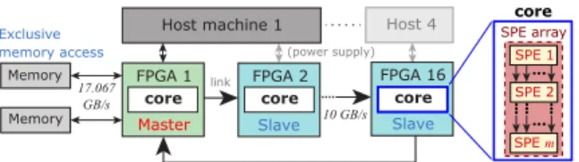
Fig. 2 FPGA cluster in 1D ring topology. SPEs are placed in the com- puting core of each FPGA.
width and achieve a higher network throughput.
In this approach, one master FPGA is adopted and from it, the cascaded FPGAs are calledslaves. Having one master involves the simplicity in the localization of com- putational data in a single memory space. Here, the mas- ter FPGA will have an exclusive memory access; therefore, eliminating the necessity of a complicated control mecha- nism over a shared memory space across the other FPGAs.
Through the PCIe interface, the pre-computational data streams are transferred from the host to the master FPGA’s memory. The master and slave FPGAs are implemented with stream computing pipelines, which accepts the data streams through the master. After the master handles the initial computations, the cascaded slave FPGAs receive the resulting data streams and handle all the consequent com- putations before returning the final results back for storage to memory. The 1D ring topology is shown in Fig. 2, which illustrates the master-slave configuration on 16 clustered FP- GAs connected to 4 host machines, with an option to scale the number of hosts and FPGAs if necessary.
3.3 Inter-FPGA Communication Subsystem
One identified challenge with multiple FPGAs is synchro- nization of data streams, since the FPGAs are operating in different clock domains. Typically, dual-clock FIFOs at both transceiver ends handle this by allowing FIFO read and write access at different clocks. Flow control manages data synchronization between different asynchronous units such as FIFOs and SPEs by supplying backpressure signals. Fur- thermore, backpressure should also be available between two communicating FPGAs. With this, we designed and implemented a credit-based flow controller[18](FC core) to add a reliability layer to any network protocol for the transceiver links.
FC core is designed to be general purpose with full- duplex symmetry, where it is implemented on both com- municating ends. In addition, it must be able to operate on either half or full-duplex mode without setting any user- defined parameter. TX must regularly sendcredits, which is an approach used to mimic the backpressure effect. FC cores on both ends are keeping a running count of the trans- mitted payload, sent indata flits. Flit is a unit for smaller chunks of a large network packet that is sent in one cy- cle. The credit-based scheme allows TX to transmit payload only when there is available RX buffer space downstream.
Credit is embedded in acontrol flit, which is the first flit sent at every TX burst. On the receiving end, RX uses the received credit to update its credit counter. Figure 3 shows
Fig. 3 Communication subsystem with FC and SL3 modules
the case of half-duplex mode between two FPGAs. Each communication subsystem includes an FC core and Serial- Lite III (SL3) core, a lightweight network protocol for high- bandwidth streaming data without a ready signal for back- pressure propagation.
In this work, communication buffer depths are consid- ered to minimize area consumption without sacrificing per- formance. TX buffer stores outgoing data flits, where it only transmits them when an end-of-packet (EOP) signal is de- tected or when it is full. This means that TX buffer should be small enough to minimize induced waiting time before transmission. However, it should also be large enough to store more data flits in a single burst. Equation (1) shows the inter-FPGA link delay:
Dlink=((link latency)×F)+(TX buffer depth)+ (RX buffer write-forward cycles) [cycles], (1) where (link latency) is the time it takes for a TX-sent flit to reach RX,F is the operating frequency, (TX buffer depth) is the TX buffering delay, and (RX buffer write-forward cy- cles) is the number of cycles before received flits become available from the RX buffer.
We also define the transmission overhead in Eq. (2), which is the ratio of control flit to the total number of flits sent in one burst. Transmission of more data flits per burst leads to a lesser overhead, which maximizes network band- width utilization. Since there is one control flit per burst, then:
(TX overhead)= 1
1+(TX buffer depth). (2) To operate at a high rate, RX buffer depth must be suffi- ciently larger than the round-trip link delay and credit update delay[18]. For bursty traffic, this large allocation allows high link utilization. Equation (3) summarizes RX buffer depth requirement:
(RX buffer depth)>(Dlink×2)+DCU, (3) where (Dlink×2) is the round-trip link delay, andDCUis the interval at which RX sends a credit upstream.
Based on these equations, we selected the communica- tion buffer depths. Figure 4 shows the effective link through- put when sending different data stream sizes with different
Fig. 4 Effective link throughput
TX buffer depths. For shorter data streams, smaller alloca- tion has a higher effective throughput due to a smaller TX buffering overhead. However, this overhead becomes neg- ligible in longer data streams, where the 3 different buffer depths converged to an effective link throughput of 7.9 GB/s.
Since we target to design a general-purpose credit-based FC, we chose to use TX buffer depth=32. Meanwhile, link la- tency is 446 ns, which is 100 cycles atF=225 MHz. With this,Dlink=(100)+(32)+(3)=135 cycles, where TX buffer depth=32 and RX buffer write-forward=3 cycles. We then selected RX buffer depth=512, which is sufficiently larger than (135×2)+(128)=398. Here,DCU=128 cycles and is a statically chosen interval that satisfies Eq. (3).
3.4 Performance Model
The performance model for stream computing with (n,m) SPE configuration[9],[11]is:
Ptheory(n,m)=nmFOpipe 1+mDCstreampipe
min(Bmem,bcore) bcore
[GFlops], (4) where Opipe is the number of operations per unit pipeline, Dpipe(n) is the pipeline depth of a unit pipeline, Bmem is available memory bandwidth, and bcore(n) is the required computing core bandwidth. Here,bcore(n)=nWpipeF, where Wpipe is the input/output width of a unit pipeline [bytes].
Since havingn-parallelized pipelines requiresntimes wider data, the total number of stream cyclesCstream is inversely proportional to n: Cstream(n) = Ngrid/n, where Ngrid is the number of computational grid points to stream. We extended Eq. (4) to estimate the performance in the multi- FPGA platform. The contributing parameters are summa- rized in Table 1.
We introduce OFPGA as the number of operations per FPGA, whereOFPGA(n,m)=nmOpipe. To stream data with Cstream cycles, the total number of operations with M cas- caded FPGAs is:
Ototal=MOFPGACstream=nmMOpipeCstream [ops]. (5) Cascading FPGAs introduces the communication links into the model. Let Blink be the available link bandwidth.
In general, when there is insufficient available bandwidth, pipeline stalls will occur. Here, we define stall ratiorstallas the ratio of stall cycles to total cycles and utilization ratio (1−rstall) as the ratio of utilized cycles to total cycles:
rstall =
⎧⎪⎪⎪⎪⎪⎨
⎪⎪⎪⎪⎪
⎩
1−Bbcorelink ,Blink<min(Bmem,bcore) 1−Bbmemcore ,Bmem<min(Blink,bcore) 0 , otherwise;
(6)
(1−rstall)= min(Blink,Bmem,bcore) bcore
. (7)
The entire computation for a single data stream takes (Cstream+Dtotal) cycles, where Dtotal(M) is the total prop- agation delay from start to end of the entire computing pipeline. Here, Dtotal(M) = M(Dcore +Dlink), where core delay Dcore(m) = mDpipe andDlink is the inter-FPGA link delay, as introduced in Eq. (1). Since pipeline stalls are an- ticipated with an insufficient available bandwidth, the total number of cycles for computation is:
Ctotal=Cstream+M(Dcore+Dlink) (1−rstall)
=Cstream+M(mDpipe+Dlink)
(1−rstall) [cycles].
(8)
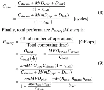
Finally, total performancePtheory(M,n,m) is:
Ptheory= (Total number of operations)
(Total computing time) [GFlops]
= Ototal
Ctotal
1
F
= MFOFPGACstream
Ctotal
= nmMFOpipeCstream(1−rstall) Cstream+M(mDpipe+Dlink)
= nmMFOpipe
1+M(mDCpipestream+Dlink)
min(Blink,Bmem,bcore) bcore .
(9)
Based on Eq. (9), the following scaling factors are iden- tified. First,nmMFOpipedefines the peak performance with Mcascaded FPGAs, wherenmFOpipeis the peak for a single
Table 1 Performance parameters
Parameters Description Unit
Ototal Total number of operations [ops]
Ctotal Total computing cycles [cycles]*
F Operating frequency [Hz]
Cstream Number of elements in data stream -
m Number of cascaded SPEs per FPGA -
n Number of parallel pipelines per FPGA -
M Number of cascaded FPGAs -
Opipe Number of operations in a unit pipeline [ops]
OFPGA Number of operations per FPGA [ops]
Bmem Available memory bandwidth [Bytes/s]
Blink Available inter-FPGA link bandwidth [Bytes/s]
Wlink Width of inter-FPGA link [Bytes]
bcore Required computing core bandwidth [Bytes/s]
Wpipe Input and output width of a unit pipeline [Bytes]
rstall Stall ratio -
Dtotal Total propagation delay [cycles]*
Dpipe Pipeline stages/delay in an unit pipeline [cycles]*
Dcore Pipeline stages/delay in a core [cycles]*
Dlink Inter-FPGA link delay [cycles]*
*All delays are measured in cycles at the same operating frequencyF.
FPGA. On the other hand, performance degradation due to pipeline overhead is indicated byM(mDpipe+Dlink)/Cstream. This suggests that the overhead increases as the data stream size gets larger with respect to the total pipeline depth M(mDpipe + Dlink). Since M FPGAs would also scale the total propagation delay, therefore, adding more FPGAs will likewise contribute to the pipeline overhead. Finally,
min(Blink,Bmem,bcore)
bcore is the effect of insufficient available band- width, caused by either the links or by havingn-parallelized pipelines in the core.
4. Results and Discussion
4.1 Implementation
The acceleration platform with master and slave FPGAs is shown in Fig. 5. Currently, it is implemented with 8 Tera- sic DE5A-NET boards on 2 host machines, with the in- tention of extending up to 16 boards on 4 hosts, as intro- duced in Fig. 2b. Each board includes an Intel Arria 10 10AX115N3F45I2SG FPGA, 2 DDR3-2133 SDRAMs, a PCI-Express (PCIe) Gen2 x8 interface, and 4 high-speed, low-latency quad small form-factor pluggable (QSFP+) transceiver links, each of which has a bandwidth of 40 Gbps. Other necessary peripherals include: 2 DDR3 con- trollers, 4 scatter-gather direct memory access (SGDMA) modules, data width converters, hardware cycle counters, and dual clock FIFOs (DCFIFO). Data-width converters (WidthConv) convert the required bit-stream width for the computation and communication modules. Different clock domains are also utilized: 250 MHz for PCIe, 266.67 MHz for DDR3 controllers, and an operating range of up to 225 MHz is available for the computing core. Each SDRAM has a peak bandwidth of 17.067 GB/s, while the two bundled 40Gbps transceiver links claimed to reach 10 GB/s. How- ever, as shown in Fig. 4, sustained link throughput with the communication subsystems averages at 7.9 GB/s. In a sin- gle FPGA, 2 communication subsystems are implemented, where the credit-based FC and SL3 cores are placed, and as reflected in Fig. 6, they leave a tiny footprint in the FPGA fabric.
For the custom computing core of the tsunami simu-
Fig. 5 Acceleration platform with master-slave FPGAs
Fig. 6 Resource utilization with different SPE array configurations
lation, different (n,m) SPE configurations are generated us- ing our domain specific language-based stream computing compiler (SPGen)[10], where all operations are in IEEE754 single precision FP format. Adders and multipliers are implemented using Intel IP cores on the FP-DSP blocks, while dividers and square root logic are generated using a FP-generation tool, FloPoCo[21]. We used (n,m) = (1,1),(1,2),(1,3),(1,4),(2,2),(1,5),(1,6) for design space exploration and utilized Intel Quartus Prime Pro 18.0 to gen- erate the entire acceleration platform design.
As a result of master FPGA having more peripher- als than its slave counterpart, it can fit only up to 5 SPEs, whereas the slave can accommodate 6 SPEs, where the lim- iting factor is the combination of both adaptive logic mod- ules (ALMs) and DSPs. It is also noteworthy that the uti- lization of DSPs is solely by the computing core only, as shown in Fig. 6. For (n,m) = (1,4) and (2,2), they used the same number of DSPs in their SPEs (nm=4); however, there is a noticeable difference in other areas like ALMs, registers (Regs), and block memories (Kbits) since havingn- parallelized pipelines allowed them to share the same stencil buffers in the SPEs[11].
4.2 Benchmark Application: Tsunami Simulation For benchmarking, tsunami simulation is implemented as the computing core in the multi-FPGA platform. Its algorithm is based on Method of Splitting Tsunami (MOST)[22],[23], which is a numerical method to solve shallow water equations for ocean-wide wave propagation.
Implementation details about MOST-based SPEs were pub- lished in [11], where evaluation on a single Intel Arria 10 FPGA was presented. SPE configurations that are uti- lized in this paper have been previously verified to obtain the same computational results with a software-based sim- ulation. Likewise, we used a 2581 x 2879 grid of real ocean-depth data to simulate the tsunami propagation in this work. Samples of FPGA-based computation visualizations can also be seen in[11].
4.3 Verification and Evaluation
We investigate the scalability and performance of the multi- FPGA platform using tsunami simulation’s SPEs, in which one SPE with nm = 1 has 288 operations. Based on
Fig. 7 Validation of performance model withCstream=116,104 cycles
Eq. (9), the peak performancenmMFOpipeis obtained with F = 225 MHz andOpipe = 288. To obtain the theoreti- cal sustained performance brought by degradation factors, Dpipe(n) = 3099 and 1808 for n = 1 and 2, respectively;
while Dlink = 135, as introduced in Sect. 3.3. For the available bandwidth, Bmem = 17.067 GB/s, and sustained Blink =7.9 GB/s. The required bandwidth for tsunami sim- ulation core isbcore(n)=n×32×0.225=7.2nGB/s, where Wpipe=32 Bytes.
Using actual ocean-depth data requires a sufficiently largeNgrid, in this case, with 2581×2879 data grid, which is equivalent toCstream(1)=7,430,699 cycles. To initially val- idate the model in Eq. (9), we first use a relatively smaller Ngrid with Cstream(1) = 116,104 cycles, which is roughly 64 times smaller than theNgridfor tsunami simulation. Us- ing up to M =4 FPGAs, we obtained the peak, theoretical Ptheory, and sustained performances of different SPE config- urations, as shown in Fig. 7. Using the hardware counters in Fig. 5, we measured the stall cycles and total computing cycles for the sustained performance ratings. Figure 7 also shows the similarity ratio between theoretical and sustained performances, which is close to 100%, therefore, validating the model in Eq. (9).
Figure 8 shows the performance evaluation of tsunami simulation with actual ocean-depth data using up toM =8 FPGAs. In Fig. 8a, its peak, theoretical, and sustained per- formances are illustrated for Cstream(1) = 7,430,699. For n=1, the available bandwidth is sufficient (Bmem>Blink>
bcore(1)), making sustained performance close to its peak.
In the case ofnm = 4, two SPE configurations are imple- mented: (1,4) and (2,2), wheren = 2 caused an increase of bandwidth requirement (Bmem > bcore(2) > Blink) when bcore(2)=2×32×0.225=14.4 GB/s. This led to pipeline stalls resulting to a lower sustained performance. ForM=8 FPGAs, (n,m) = (1,5) obtained the highest performance
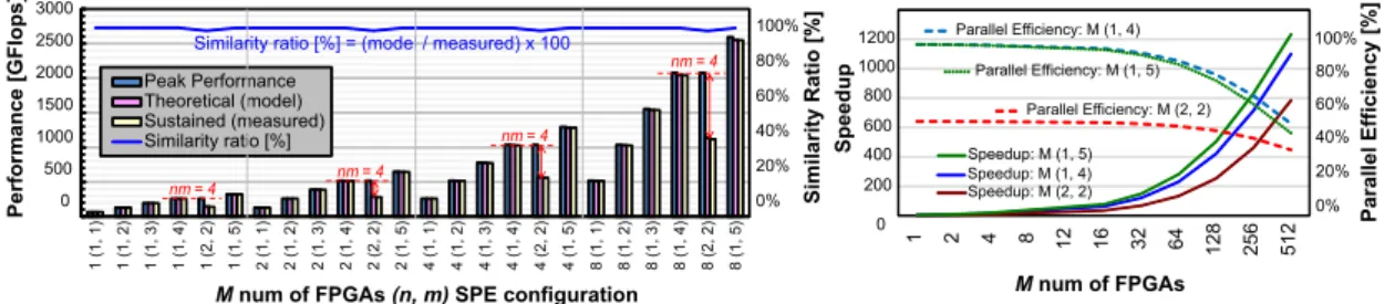
Fig. 8 Performance evaluation of tsunami simulation
with 2.5 TFlops, which is 98% of its peak performance.
This shows that the total pipeline depth of 8×5 =40 cas- caded SPEs is sufficiently enough to accommodate the in- putCstream, without being affected by the pipeline overhead.
In the case where Cstream(1) = 116,104 cycles, as shown in Fig. 7, the pipeline overhead is visibly reflected with the significant difference between the peak and sustained per- formances as the pipeline depth increases.
Figure 8b shows the speedup and parallel efficiency of the largest SPE configurations that can fit the mas- ter and slave FPGAs for efficient resource utilization:
(1,5),(1,4), and (2,4). The expected speedup is achieved forn = 1, whenM FPGAs are increased. The differences among the 3 SPE configurations are significantly observed with more FPGAs due to the pipeline overhead caused by the fixed ocean-depth data grid. (1,5) has the best speedup but its parallel efficiency is slightly lower than (1,4)’s, due to the pipeline overhead when the problem size of com- putation is maintained. (2,2) has the lowest speedup rate and efficiency because of the insufficient bandwidth caused by havingn-parallelized pipelines. This illustrates the per- formance model’s prediction on the factors causing perfor- mance degradation, which in this case, is the bottleneck in the inter-FPGA links due to insufficientBlink.
With this, expanding the design space with multiple FPGAs supports further performance scaling. The key is finding the balance between the M, n, and m to achieve the best speedup and parallel efficiency rates. In the case of tsunami simulation, the large ocean-depth data grid al- lowed performance scaling when we increase the pipeline depth over multiple FPGAs. Ideally,n-parallelized pipelines would be the best approach since it would mean lesser com- puting cycles. However, this requires a larger bandwidth requirement, whereBlink was not able to satisfy. Based on Fig. 8b, implementing (n,m) =(1,5) SPE array is the best option in terms of area, speedup, and efficiency, even though the latter is slightly lower than (1,4)’s. With the currently utilized data grid, cascading up to 16(1,5) = 80 SPEs and 32(1,5) =160 SPEs, have parallel efficiencies of 97% and 94%, respectively, which can still be acceptable rates. How- ever, M >32 FPGAs will bring a rapid rate of decreasing efficiency due to pipeline overhead.
5. Conclusions
This paper presents the design and architecture of a deeply
pipelined stream computing platform on a 1D ring of master and slave FPGAs with communication subsystem. Tempo- ral and spatial parallelism in the custom computing core are explored to efficiently utilize the hardware resources. Fine- grained temporal parallelism is achieved by m-cascaded SPEs while spatial parallelism is explored by having n- parallelized pipelines. By cascading the SPEs on multiple FPGAs, a deeper computing pipeline with a vast design space is achieved to support further performance scaling.
Performance characteristics of the inter-FPGA links were also investigated, where communication buffer depths affect the sustained performance.
A performance model is also presented and validated by implementing a custom practical application on the stream computing prototype platform with 8 cascaded FP- GAs at 80 Gbps links. With this, a practical and efficient exploration of the vast design space can be achieved with the model. Tsunami simulation is implemented and eval- uated on the master and slave FPGAs. The highest scaled performance on 8 FPGAs is achieved with a single pipeline of 5 cascaded SPEs (n,m)=(1,5), where 40 SPEs in a deep pipeline delivered a scaled performance of 2.5 TFlops and a parallel efficiency of 98%.
Future work includes performance estimation and pa- rameter optimization for forthcoming FPGAs such as the In- tel Stratix 10 FPGAs, which have a larger design area and wider available bandwidth, where we can explore multiple n-parallelized pipelines. In addition, we intend to include applying the stream computing platform to other network topologies such as a 2D torus with multiple FPGAs to fur- ther scale the performance.
Acknowledgments
This research was partially supported by Grant-in-Aid for Scientific Research (B) No.17H01706 from MEXT, Japan.
The authors thank the support of Intel university program.
References
[1] A. Mondigo, T. Ueno, D. Tanaka, K. Sano, and S. Yamamoto,
“Design and scalability analysis of bandwidth-compressed stream computing with multiple FPGAs,” Proceedings of the 12th Interna- tional Symposium on Reconfigurable Communication-Centric Sys- tems-on-Chip, ReCoSoC 2017, Madrid, Spain, pp.1–8, IEEE, 2017.
[2] A. Mondigo, K. Sano, and H. Takizawa, “Performance estimation of deeply pipelined fluid simulation on multiple FPGAs with high-
speed communication subsystem,” Proceedings of the 29th Annual IEEE International Conference on Application-specific Systems, Ar- chitectures and Processors, ASAP 2018, pp.1–4, IEEE, 2018.
[3] W. Vanderbauwhede and K. Benkrid, eds., High-Performance Com- puting Using FPGAs, Springer New York, New York, NY, 2013.
[4] M. Vestias and H. Neto, “Trends of CPU, GPU and FPGA for high- performance computing,” Proceedings of the 2014 24th Interna- tional Conference on Field Programmable Logic and Applications (FPL), Munich, Germany, pp.1–6, IEEE, Sept. 2014.
[5] M. Parker, “Understanding peak floating-point performance claims,”
Technical report (white paper): Intel, WP-01222-1.1, 2017.
[6] M. Langhammer and B. Pasca, “Floating-point DSP block archi- tecture for FPGAs,” Proceedings of the 2015 ACM/SIGDA Interna- tional Symposium on Field-Programmable Gate Arrays - FPGA ’15, New York, New York, USA, pp.117–125, ACM, 2015.
[7] M. Lin, S. Cheng, and J. Wawrzynek, “Cascading deep pipelines to achieve high throughput in numerical reduction operations,” 2010 International Conference on Reconfigurable Computing Cascading, Quintana Roo, Mexico, pp.103–108, IEEE, 2010.
[8] K. Dohi, K. Okina, R. Soejima, Y. Shibata, and K. Oguri,
“Performance modeling of stencil computing on a stream-based FPGA accelerator for efficient design space Exploration,” PAPER Special Section on Reconfigurable Systems, IEICE Transactions, vol.E98-D, no.2, pp.298–308, 2015.
[9] K. Sano and S. Yamamoto, “FPGA-based scalable and power-effi- cient fluid simulation using floating-point DSP blocks,” IEEE Trans.
Parallel Distrib. Syst., vol.28, no.10, pp.2823–2837, 2017.
[10] K. Sano, “DSL-based design space exploration for temporal and spa- tial parallelism of custom stream computing,” Proceedings of the Second International Workshop on FPGAs for Software Program- mers (FSP 2015), pp.29–34, Aug. 2015.
[11] K. Nagasu, K. Sano, F. Kono, and N. Nakasato, “FPGA-based tsunami simulation: Performance comparison with GPUs, and roofline model for scalability analysis,” Journal of Parallel and Dis- tributed Computing, vol.106, pp.153–169, Aug. 2016.
[12] M.C. Herbordt, T. VanCourt, Y. Gu, B. Sukhwani, A. Conti, J.
Model, and D. DiSabello, “Achieving high performance with FP- GA-based computing,” Computer, vol.40, no.3, pp.50–57, March 2007.
[13] A. Azarian and J.M.P. Cardoso, “Coarse/fine-grained approaches for pipelining computing stages in FPGA-based multicore archi- tectures,” Proceedings of the European Conference on Parallel Pro- cessing: Euro-Par 2014: Parallel Processing Workshops, vol.8806, pp.266–278, Springer, 2014.
[14] S. Murtaza, A.G. Hoekstra, and P.M.A. Sloot, “Cellular automata simulations on a FPGA cluster,” The International Journal of High Performance Computing Applications, vol.25, no.2, pp.193–204, May 2011.
[15] Y. Kono, K. Sano, and S. Yamamoto, “Scalability analysis of tightly-coupled FPGA-cluster for lattice Boltzman computation,”
Proceedings of the 22nd International Conference on Field Pro- grammable Logic and Applications (FPL 2012), pp.120–127, IEEE, 2012.
[16] A.T. Markettos, P.J. Fox, S.W. Moore, and A.W. Moore, “Intercon- nect for commodity FPGA clusters: Standardized or customized?,”
Conference Digest - 24th International Conference on Field Pro- grammable Logic and Applications, FPL 2014, pp.1–8, 2014.
[17] S.-W. Jun, M. Liu, S. Xu, and Arvind, “A transport-layer network for distributed FPGA platforms,” 2015 25th International Conference on Field Programmable Logic and Applications (FPL), London, UK, pp.1–4, IEEE, Sept. 2015.
[18] N.T. Kung and R. Morris, “Credit-based flow control for ATM net- works,” IEEE Netw., vol.9, no.2, pp.40–48, 1995.
[19] R. Jain, “Congestion control and traffic management in ATM net- works: Recent advances and a survey,” Computer Networks and ISDN Systems, vol.28, no.13, pp.1723–1738, Oct. 1996.
[20] S. Kamolphiwong, A.E. Karbowiak, and H. Mehrpour, “Flow con-
trol in ATM networks: a survey,” Elsevier Computer Communica- tions, vol.21, no.11, pp.951–968, 1998.
[21] “FloPoCo Project WEB.”
[22] V. Titov and F. Gonzales, “Implementation and testing of the Method of Splitting Tsunami (MOST) Model,” 1997.
[23] M. Lavrentiev-jr, A. Romanenko, V. Titov, and A. Vazhenin, “High- performance tsunami wave propagation modeling,” Parallel Com- puting Technologies, Lecture Notes in Computer Science, vol.5698, pp.423–434, Springer, Berlin, Heidelberg, 2009.
Antoniette Mondigo received B.S. and M.E. degrees in Computer Engineering from University of San Carlos, Philippines in 2006 and 2012, respectively. She is now a Ph.D. stu- dent in the Graduate School of Information Sci- ences at Tohoku University and at the same time, a student trainee in the Processor Research Team at Riken Center for Computational Science. Her research interests include architecture and de- sign of reconfigurable systems with FPGAs. She is a student member of IEEE.
Tomohiro Ueno is currently a postdoctoral researcher of the Processor Research Team at Riken Center for Computational Science. He received his Ph.D. from the Graduate School of Information Sciences, Tohoku University, in 2016. Since then he had been a postdoctoral researcher in the Graduate School of Engineer- ing at Tohoku University for a member of Im- PACT project until 2017. His research interests include hardware architectures, hardware algo- rithms, data compression, and communication networks for HPC. He is a member of IEEE and IPSJ.
Kentaro Sano is the leader of the Proces- sor Research Team at Riken Center for Compu- tational Science. He received his Ph.D. from the Graduate School of Information Sciences, Tohoku University, in 2000. Until 2017, he had been an associate professor in the Gradu- ate School of Information Sciences at Tohoku University. His research interests include novel architectures, hardware algorithms, system soft- ware, HLS compilers for HPC systems and re- configurable systems with FPGAs. He is a member of IEEE, ACM, and IPSJ.
Hiroyuki Takizawa is currently a pro- fessor of Cyberscience Center and Graduate School of Information Sciences, Tohoku Uni- versity. His research interests include HPC sys- tems and their applications. He received the B.E. Degree in Mechanical Engineering, and the M.S. and Ph.D. Degrees in Information Sci- ences from Tohoku University in 1995, 1997, and 1999, respectively. He is a member of IEEE CS, ACM SIGHPC, and IPSJ.