Experimental and Numerical Evaluation of Open Hole Tensile Properties
of 3D Printed Continuous Carbon Fiber Reinforced Thermoplastics
by
Yamato H
OSHIKAWA
1,
Keiichi S
HIRASU
1, Junpei T
SUYUKI
and Tomonaga O
KABE
(Department of Aerospace Engineering, Tohoku University, Miyagi, Japan)
Ryo H
IGUCHI
(Department of Aeronautics and Astronautics, The University of Tokyo, Tokyo, Japan)
Kohei Y
AMAMOTO
and Yasuhisa H
IRATA
(Department of Robotics, Tohoku University, Miyagi, Japan) Abstract
To widen the application of 3D printed continuous carbon fiber-reinforced thermoplastics (CFRTPs), understating of both their open hole mechanical properties and fracture mechanisms is of a pressing need. In this study, tensile tests were performed on 3D printed CFRTP plates with open holes and a quasi-3D extended finite element method (XFEM) program was used to compare the experimental results with the numerical analysis. The specimens were formed using a commercially available 3D printer followed by drilling of the hole. The laminate structure of the printed specimens was [0/90]2s. An X-ray computed tomography (CT)
observation of the fabricated specimens showed no delamination was introduced by the drilling process, even though in-plane and interlayer voids due to filament undulation were observed. Experimentally obtained Young’s modulus and OHT strength were 35.6 ± 1.2 GPa and 185.0 ± 2.7 MPa, respectively. The XFEM accurately predicts both Young’s modulus and OHT strength and their values are 36.1 GPa and 191.0 MPa, respectively. The printed specimens failed to leave brittle fracture due to fiber break at the hole edge, which can be also simulated by the XFEM used in this study.
(Received January 11, 2021) Key Words: 3D printing, CFRTPs, Continuous carbon fibers, Open hole tensile testing, XFEM
1. Introduction
In recent years, with the development of additive manufacturing technology, it has been applied to various industries. One of the main features of this technology is that it does not require a mold for manufacturing, thus shortening the development lead time, and that it can easily form complex shapes that are difficult to form by conventional processing. The most common 3D printing method is fused deposition modeling (FDM), also known as fused filament fabrication (FFF), in which thermoplastic resins are heated beforehand and injection molding is performed using a nozzle. This method does not require curing, simplifies processing machines and equipment, and is characterized by its high productivity. However, due to low mechanical properties of thermoplastics, they have long been considered unsuitable for industrial use and have been used in household products and science, technology, engineering and mathematics (STEM) education. Because of the aforementioned advantages, carbon fiber-reinforced thermoplastics (CFRTPs) have recently been focused to improve mechanical properties. Particularly, it has been noted that, Markforged developed the first ever commercial FDM-based multifunctional printing press in 2014, which provides a printing head with two independent extrusion nozzles for plastic and reinforcing fiber feed [1].
In this way, the application of continuous carbon fiber to the FDM process will expand the application of CFRTPs to more general mechanical products. Therefore, it is important to understand the mechanical properties of CFRTPsformed by the FDM in order to improve the reliability of products and increase the degree of freedom in design. Todoroki et al. [2] fabricated 0°, 90°, ± 45°, and lay-up direction type specimens using the MarkTwo printer, and investigated their mechanical properties. Many studies detailing the mechanical properties of such 3D printed composites have been published [1]. On the other hand, stress concentrations around small holes (for fasteners) in composites have been studied for decades, especially in aerospace. Open-hole tensile (OHT) strength is a
determining factor in the design of composite structures. The hole triggers stress concentrations and inherently reduces the net section volume. OHT testing is a prerequisite to leverage the use of composites in load-bearing structural applications [3]. A large amount of research has been conducted in the area of OHT in carbon fiber reinforced composites (CFRPs) prepared by hot pressing. Unlike the hot-pressed CFRPs, 3D printed parts do not require a secondary machining process to form holes or any other geometrical features[4, 5]. However, the OHT strength and fracture mechanisms of 3D printed CFRTPs have little in common with such CFRPs, and there is a lack of understanding of the basic mechanical properties of the 3D printed CFRTPs with drilled hole similar to conventional CFRP open-hole specimens. Additionally, a mesoscale analysis that can predict the progressive damage and resultant failure of 3D printed CFRPs is needed for deep understanding of fracture mechanisms.
In this study, we prepared continuous carbon fiber-reinforced thermoplastics using a commercially available 3D printer, and evaluate the OHT properties. Furthermore, a numerical analysis using the quasi 3D extended finite element method (XFEM) was performed to investigate the fracture mechanisms and compare the experimental results.
2. Experimental Procedures 2.1 Materials
The filament used was a 0.4 mm diameter continuous carbon fiber reinforced nylon filament (CFF, supplied by Markforged, Cambridge, MA, USA). There were 1000 carbon fibers in the CFF, and the fiber volume fraction was approximately 35% [6, 7]. The CFF was supplied for 3D printers to fabricate unidirectional CFRTP coupon specimens.
2.2 3D printer
Many groups have reported continuous CFRTP samples fabricated by a commercially available FDM 3D printer (MarkOne or MarkTwo, Markforged) [1-8]. However, it has been shown to be impossible to print CFFs without a nylon surface layer [2]. Todoroki et al. [2] reported that a
nylon surface layer is printed first. After printing the nylon layer, the nylon filament is removed from the 3D printer, and the tensile test specimen is printed by CFF. This process gives a specimen without the surface nylon layer. In this study, to avoid the process of peeling the specimen from the nylon layer, we modified a commercially available Prusa MK3S (Prusa Research, Prague, Czech) to print the CFF as shown in Figure 1a. One of the problems of 3D printing of CFF is that the CFF spreads and becomes tangled due to its high elasticity. Therefore, a feed extruder, i.e., the stepping motor that feeds the filament near the nozzle is placed at a distance (Figure 1a). Such a method is called the Borden method. In the Borden type, the feed extruder is attached to the frame of the printer and the filament is delivered to the nozzle. In this study, a PTFE tube with the same inner diameter as that of the CFF was inserted into the nozzle (Figure 1b). In addition, the nozzle attached to MarkTwo was used to improve the adhesion between CFFs (Figure 1c).
2.3 Printing procedure
Since the 3D printer used in this study does not have a filament cutting mechanism, the printing path of the specimen must be a single stroke for each layer. Print paths are written as parameterized G-code scripts and the resulting print paths for the 0° and 90° layers are shown in Figures 1d and e, respectively. For each layer, the coordinates in G-code format were output, which created a unidirectional sheet of fiber on each layer by printing all fibers parallel to each other in a single angular orientation, with 180° turns when the path reaches the edge of the part. In addition, a detour route from the end point to the start point was prepared for each layer to match the start and end points of printing of each layer. This path was cut off after printing was completed.
The dimensions of the specimen were set at 203.0 × 30.8 × 1.2 mm3, but the actual dimensions were measured to
be 203 × 32.09 × 1.475 mm3. The stacking configuration was
[0/90]2s. The printing conditions are summarized in Table I.
2.4 OHT testing
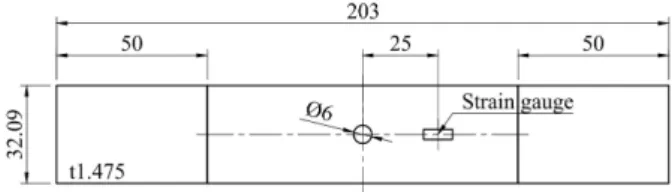
The OHT tests were performed using an Instron 5982 testing machine. The open-hole specimens are 203.0 mm long and 30.8 mm wide with 6.00 mm center hole which is drilled by a drilling machine. Figure 2 shows the schematic drawing of OHT test specimen. The strains were determined using strain gauges (Kyowa Electronic Instruments Co., Ltd., Japan) which were attached to the specimen. The tensile rate was 1 mm/min. The tensile tests were conducted four times, and the
averaged values were used. The Young's modulus was calculated from the slope of the stress-strain diagram when the strain was between 0.1 and 0.3%. The tensile stress was calculated by dividing the load by the full cross-sectional area (32.09 × 1.475 mm2). The digital image correlation (DIC)
method was used to track the surface strain fields during OHT testing. A random speckle pattern is sprayed on one surface of the specimens. In-situ images are captured by a digital camera. The images were captured every 2 kN. MATLAB software was used to determine the material deformation based on the deformation of the speckle pattern.
2.5 X-ray computed tomography
Before OHT tests, specimens were imaged using a ScanXmate-L080TT X-ray µ-CT system (Comscantecno Corp., Yokohama, Kanagawa, Japan). The X-ray voltage and current were 60 kV and 70 μA, respectively. The image size of XY plane, ZX plane and YZ plane were 1152×1296, 348×1152 and 1296×348 pixels, respectively. The scanning resolutions in the three dimensions were the same, 2.83 µm/pixel.
Fig.2 Schematic drawing of OHT test specimen.
Table I Specimen parameter and printing conditions Size 203.0×30.8×1.2 mm3
Laminate structure [0/90]2s
Nozzle temperature 270℃ Bed temperature 60℃ Print speed 7 mm/sec Distance between filaments 0.7 mm Pitch of layers 0.15 mm
3. Numerical Simulation
To compare the experimental results with the numerical analysis, a quasi-3D XFEM was applied. Detailed explanation of the XFEM for OHT tests has been provided in a previous study [9]. In this XFEM, the pressure-dependent elasto-plastic constitutive law was utilized to reproduce the pre-peak nonlinear behavior, and a cohesive zone model (CZM) including a zig-zag softening law combined with an XFEM and interface element was implemented to reproduce the interactive progression of matrix cracks and delamination. In addition, the Weibull criterion was employed to predict size-dependent longitudinal failure dominated by fiber breakage [9]. In this analysis, a triangular two-dimensional mesh model was created by Abaqus followed by extruding these triangular elements in the thickness direction by XFEM as shown in Figure 3. Multiple matrix cracks are pre-inserted independently of the mesh by XFEM at the position where the cracks are expected to occur in each layer. The mesh sizes in the region around the hole (away from the hole) were determined based on the Mode I (II) cohesive zone lengths [10]. The temperature change in the thermal analysis was set to –240 K from the nozzle temperature to room temperature. The physical properties used in the analysis are shown in Table II.
Fig.3 (a) Simulation model and boundary conditions for OHT specimen. (b) Pre-inserted crack locations.
4. Results 4.1 OHT specimen and X-ray CT image
Photographs and X-ray CT images of the OHT specimens fabricated in this paper are shown in Figure 4. As shown in Figure 4c, the filaments ejected from the printer are oriented roughly in one direction in the print direction, but they also appear to be curved, indicating voids between the filaments. Substantial voids which are distributed unevenly within the samples are clearly observed not only in the above plane but also between layers. In particular, there are many voids between the 0° and 90° layers, and few voids in the layer with two overlapping 90° layers in the center. The latest reports showed that the void content in the samples fabricated using CFF and Mark Two printer ranged from 10.3% to 14.3%, with the average being 12% [8] which is much higher than that in the composite laminates manufactured by traditional techniques such as the resin transfer molding and autoclave. On the other hand, no delamination due to the drilling process was observed. The slight curvature in the cross-sectional CT image (Figure 4d) is thought to be due to warping caused by 3D printing.
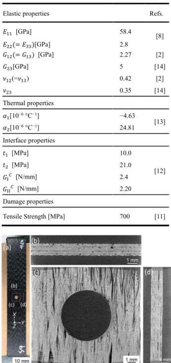
Table II Mechanical properties of 3D printed laminate using CFF.
Elastic properties Refs.
𝐸 [GPa] 58.4 [8] 𝐸 (= 𝐸 )[GPa] 2.8 𝐺 (= 𝐺 ) [GPa] 2.27 [2] 𝐺 [GPa] 5 [14] 𝜈 (=𝜈 ) 0.42 [2] 𝜈 0.35 [14] Thermal properties 𝛼 [10−6 °C−1] −4.63 [13] 𝛼 [10−6 °C−1] 24.81 Interface properties 𝑡 [MPa] 10.0 [12] 𝑡 [MPa] 21.0 𝐺 [N/mm] 2.4 𝐺 [N/mm] 2.20 Damage properties
Tensile Strength [MPa] 700 [11]
Fig.4 (a) Photograph and (b–d) X-ray CT images of fabricated OHT specimen: (b) YZ plane, (c) XY plane and
(d) ZX plane. 4.2 OHT tests
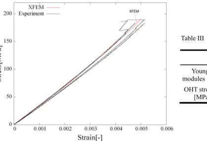
The stress-strain diagram and results of the OHT tests on the printed specimens are shown in Figure 5 and Table III, respectively. Of the four tested samples, all samples underwent failure in a brittle manner even though the variation of strain before fracture in some specimens was seen which is due to delamination of the surface layer. The average OHT strength and Young’s modulus were 185.0 ± 2.7 MPa and 35.6 ± 1.2 GPa, respectively.
The contour plot of the strain distribution at the tensile load of 8 kN (tensile stress of 167 MPa which is 90% of peak stress) is shown in Figure 6. Positive and negative values denote elongation due to tensile stresses and contraction because of compression, respectively. The longitudinal strain is concentrated near the edge of the hole, and it is expected
that the specimen will fracture from here. As shown in Figure 7, the specimen actually fractured from the edge of the hole. The shear strain was distributed radially around the circular hole. The transverse strain was negative as a whole because of the Poission’s effect. These results show a contrast around the circular hole, which is similar to the strain distribution in the 0° layer known from previous studies [15, 16].
Hallet et al. reported that fracture can be classified into three forms; brittle, pull-out and delamination [17]. Figure 7 shows an enlarged view of the fractured specimens. In this study, the samples failed to leave brittle fracture (Figure 7a) due to fiber break at the edge of the drilled hole (maximum longitudinal tensile stress site), and the delamination was also observed on one side of some specimens (Figure 7b). This delamination may be caused by residual stress and void formation during printing. During the 3D printing process, a new layer of material is instantaneously deposited at melting temperature on a substrate (the part built so far) at chamber temperature, and is subjected to thermal contraction while it cools [18]. The platform counteracts the shrinkage of the layer by reaction forces on the bottom plane of the part. The torque
of such forces with respect to the midplane of the part leads to elastic stresses, which result in residual bending deformation once the part is removed from the platform. Especially, for the 0° layer, the coefficient of thermal expansion is very small and there is almost no shrinkage, while the 90° layer shrinks as much as the base polymer matrix. Thus, the effect of warpage due to thermal shrinkage is noticeable when layers with different fiber directions are laminated. In fact, the slight warping was observed in the specimens as shown in Figure 4d. Therefore, it is possible that the specimen used in this study had tensile residual stress in the top layer and compressive residual stress in the bottom layer of the laminate. Further studies should be carried out to examine the effect of the thermal residual stresses on the warpage and OHT strength experimentally and analytically. As mentioned above, He et al. [8] showed that the void content of the specimen printed by MarkTwo is reported to be 12%, which is much higher than that of conventional CFRP laminates. As shown in Figure 4d, more voids were found between the 0° and 90°layers, suggesting that voids are easily introduced when printing on top of layers with different stacking directions.
Table III Young’s modulus and OHT strength obtained by XFEM and tensile tests
XFEM Experiment Young’s
modules [GPa] 36.1 35.6 ± 1.2 OHT strength
[MPa] 191.0 185.0 ± 2.7
Fig.5 Comparison of experiment and predicted stress-strain curves.
Fig.6 Strain distribution at a stress level around 167 MPa in the specimen obtained by DIC: (a) longitudinal strain, (b) shear strain and (c) transverse strain.
- 53 -
Fig. 7 Photograph of fractured specimen: (a) brittle
fracture and (b) brittle fracture and delamination. Fig. 8 Damage distribution at the tensile stress of (a) 13.7 MPa and (b) 187.8 MPa obtained by XFEM. The results depict 80% damaged crack surfaces and interfaces.
4.3XFEM analysis
The predicted stress-strain curve is compared with the experimental ones in Figure 5, where the predicted curve is in reasonable agreement with experiments. The predicted Young’s modules and OHT strength were 36.1 GPa and 191.0 MPa , respectively (Table III), and the prediction errors were 3.2% and 1.4%. Thus, it is suggested that the XFEM model used in this study can be applied to 3D printed CFRTPs.
When the tensile stress reached at 191.0 MPa, the Weibull criterion was satisfied without any drop of tensile stress in the XFEM model and, consequently, the failure mode was regarded as the ‘‘brittle or pull-out”. On the other hand, internal damage distributions at the tensile stress of 10MPa and just before fracture by XFEM shown in Figure 8 indicate that splitting occurs in the 0° layer as soon as tensile stress is applied, and matrix cracking also occurs in the 90° layer as the load increases. This is attributed to the fact that the maximum traction of Mode I (t1), and Mode II (t2) [12] used in the
analysis are smaller than those of conventional CFRP laminates. On the other hand, Figure 8b shows a small amount of delamination near the circular hole, while delamination is observed at the 0°/90° interface in some of the experimental samples (Figure 7b). This is due to the introduction of many voids in the 3D printing as shown in Figure 4. In conventional CFRTP laminates, the load drop occurs when the 0° layer splitting and related delamination propagate unsteadily. In the analysis results obtained in this study, splitting, matrix cracking and slight delamination were observed at an early stage, but the load did not decrease, indicating that the main fracture mechanism was brittle fracture associated with fiber breakage. Therefore, the above damage is considered to have no significant effect on the stiffness or OHT strength of the specimens.
5. Conclusion
In this study, we conducted the OHT tests of 3D printed [0/90]2s CFRTPs, and the XFEM was applied for
validation of experimental data. Experimentally obtained Young’s modulus and OHT strength are 35.6 ± 1.2 GPa and 185.0 ± 2.7 MPa, respectively. The Young’s modulus and OHT strength evaluated by XFEM are 36.1 GPa and 191.0 MPa, respectively, which is reasonable agreement with the experimental values. X-ray CT observation of the fabricated specimens showed that no delamination was introduced by the drilling process, but in-plane and interlayer voids were observed due to filament undulation during fabrication. The DIC was used as a supporting tool for evaluation of strain distribution, where the tensile strain in the longitudinal direction was the highest at the edge of the drilled hole, which
is considered to be the point of fracture. Indeed, the specimens failed to leave brittle fracture due to fiber break at the hole edge even though the delamination was also observed on one side of some specimens. In the XFEM, on the other hand, the brittle fracture due to fiber rupture was the main fracture mechanism and no delamination failure mode was observed. Nonetheless, the Young's modulus and OHT strength did not differ significantly between the experimental and XFEM results, suggesting that the mechanical properties of orthotropic specimens are less affected by the interlaminar voids and delamination.
References
1. Kabir, S.M.F., Mathur, K. and Seyam, A-F. M., A critical review on 3D printed continuous fiber-reinforced composites: History, mechanism, materials and properties, Composite Structures, 232:11476 (2020).
2. Todoroki, A., Oasada, T., Mizutani, Y., Suzuki, Y., Ueda, M., Matsuzaki, R and Hiranoe, Y., Advanced Composite Materials, 29:147-162 (2020).
3. Pyl, L, Kalteremidou, K.-A. and Hemelrijck, D.V., Exploration of the design freedom of 3D printed continuous fibre-reinforced polymers in open-hole tensile strength tests, Composites Science and Technology, 171: 135-151 (2019).
4. Sanei, HR.S., Arndt, A., and Doles, R., Open hole tensile testing of 3D printed continuous carbon fiber reinforced composites, Journal of Composite Materials, 54(20): 2687–2695 (2020).
5. Zappino, E., Filippi, M. , Pagani, A., Petiti, M., Carrera, E., Experimental and numerical analysis of 3D printed open-hole plates reinforced with carbon fibers, Composites Part C: Open Access, 2: 100007 (2020). 6. Blok, L.G., Longana, M.L., and Yu, H., Woods, B.K.S.,
An investigation into 3D printing of fibre reinforced thermoplastic composites, Additive Manufacturing, 22: 176-186 (2018).
7. Chacóna, J.M., Caminero, M.A., Núñez, J.P., García-Plaza, E., García-Moreno, I., and Revert, J.M., Composites Science and Technology, 181:107688 (2019). 8. He, Q., Wang, H., Fu, K., Ye ,L., 3D printed continuous
CF/PA6 composites: Effect of microscopic voids on mechanical performance, Composites Science and Technology, 191: 108077 (2020).
9. Higuchi, R., Okabe, T., Nagashima, T., Numerical simulation of progressive damage and failure in composite laminates using XFEM/CZM coupled approach, Composites Part A: Applied Science and Manufacturing, 95: 197-207 (2017).
- 54 -
Materials System, Vol.38 10. Harper P.W. and Hallett S.R., Cohesive zone length innumerical simulations of composite delamination, Engineering Fracture Mechanics, 75(16): 4774–92 (2008).
11. Zhang, H., Dickson, N.A., and Sheng, Y., McGrail, T., Dowling, P.D., Wang, C., Neville, A., and Yang, D., Failure analysis of 3D printed woven composite plates with holes under tensile and shear loading, Composites Part B: Engineering, 186: 107835 (2020).
12. Reis, J.P., Moura, M.F.S.F., Moreira., de, R.D.F., Silva, F.G.A., Pure mode I and II interlaminar fracture characterization of carbon-fibre reinforced polyamide composite, Composites Part B: Engineering, 169: 126-132 (2019).
13. Kousiatza, C., Tzetzis, D., Karalekas, D., In-situ characterization of 3D printed continuous fiber reinforced composites: A methodological study using fiber Bragg grating sensors, Composites Science and Technology, 174: 134-141 (2019).
14. Sauer, M.J., Evaluation of the Mechanical Properties of 3D Printed Carbon Fiber Composites, Electronic Theses andDissertations, 2436 (2018).
15. Oz, E.F., Mehdikhani, M., Ersoy, N., Lomov, V.S., In-situ imaging of inter and intra-laminar damage in open-hole tension tests of carbon fibre-reinforced composites, Composite Structures, 244:112302 (2020).
16. Habibi, M., Laperrière, L., Digital image correlation and acoustic emission for damage analysis during tensile loading of open-hole flax laminates,Engineering Fracture Mechanics, 228:106921 (2020).
17. Hallett, S.R., Green, B.G., Jiang, W.G., Wisnom, M.R., An experimental and numerical investigation into the damage mechanisms in notched composites, Composites Part A: Applied Science and Manufacturing, 40: 613-624 (2009).
18. Armillotta A., Bellotti, M., Cavallaro, M., Warpage of FDM parts: Experimental tests and analytic model, Robotics and Computer-Integrated Manufacturing, 50: 140-152 (2018).