����
�������������
��� ��* ��������� �237-0061� �������������� *[email protected] �2007 � 5 � 31 ���; 2007 � 9 � 27 ������ ����������������������������������SAM������� �������������������������������������������� ������������������������������[J. Surf. Anal. 11, 71 (2004)]��� �������������������������������������������� ��������������(1)����������������������������� �������(2)������������������������������������ ����(3) ���� 200 nm �������������������������������� �������������������������������������������� ��������������The Secondary Electron Emission Characteristics of
Carbon Materials
Sawa ARAKI*
NISSAN ARC, LTD.,
1, Natsushima, Yokosuka, 237-0061, Japan
(Received: May 31, 2007; Accepted: September 27, 2007)
The secondary electron emission characteristics of various carbon materials have been studied using a conventional scanning Auger microscope (SAM) and a specially designed sample holder with a Faraday-cup attachment. In previous investigations using this technique, we confirmed that the secondary electron emis-sion coefficient � was largely dependent on the surface composition [J. Surf. Anal. 11, 71 (2004)]. The pre-sent study examined the secondary electron emission characteristics of carbon materials having various sur-face structures, with the same sursur-face composition. The results clarified the following points. (1) � of all the carbon materials examined was small in comparison with other materials, suggesting that they have an effect of restraining secondary electron emissions. (2) The change in � due to an increase in surface roughness var-ied between the low and high regions of primary electron energy. (3) � was not dependent on the substrate at a depth below 200 nm. In evaluating �, it should be kept in mind that � is affected by not only the surface composition but also the surface structure, orientation, and surface roughness of the material.
1. ����
���������������������� ����������������������� ����������������������� ����������������������� ����Secondary Electron Emission Coefficient�SEEC� ����������������������� ����������������������� ����������������������� ����������������������� ����������������������� 2. ����������� ����������������������� ����2s ��� 2p ���������spn��� ����������������������� ����������������������� ���������������������� �������������������� ������sp2���������������
���Highly Oriented Pyrolytic Graphite�HOPG��
������C60��������������
�Single-Walled Carbon Nanotubes�SW-CNT���� �����������Multi-Walled Carbon Nano-tubes�MW-CNT������������ 0.3�m� 0.01 �m ������������������� Si ���Al2O3��sp3������������� ����������������������� ��������������� TEM ����� ���������������1 ���� ���������������������� ����������������������� ��������PHI ��Model-4300������ AES ��������������������� pA ��������������������� ���� ����������������������� ������������Ip���������� �������������������Ia��� ����������������������� ����������������������� ����������������������� ����(�������)�(�������)��� ����������������������� ������������AES ��������� ��������������Is�������Ip ������Ia�� a p s I I I � � (1)
� � � � � � � � � � � � � � � � � � � Table 1 Sample information.
Sample Purity Supplier Sample detail Ion etching
time [min.] other information
HOPG >99%*1 Veeco cleavage 0
C60 99.9+% NILACO pressed powder 0.5
SW-CNT 50-70wt.% ALDRICH pressed powder 0.5
MW-CNT 10-40wt.% ALDRICH pressed powder 0.5
Carbon plate (Ra=0.3 �m) 99.98% NILACO as-received 0.5
Carbon plate (Ra<0.01 �m) 99.98% NILACO as-received 0.5
Carbon coat (200 nm)/Au >99%*1 � vapor deposition 0.5 amorphous (by TEM)
Carbon coat (200 nm)/Si >99%*1 � vapor deposition 0.5
Carbon coat (200 nm)/Al2O3 >99%*1 � vapor deposition 0.5 Al2O3(500 nm) on Al.
Carbon coat (1 �m)/glass >99%*1 � vapor deposition 0.5
Diamond >99%*1 DIATOME cleavage 0 artificial
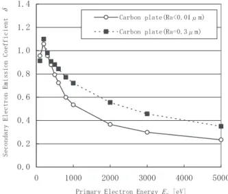
����������������������� ��������� p a p I I I � � � (2) ���������������������� ������100�5000 eV�������� 25 pA� ��������500 �m�400 �m �������� ��������AES ������������� ���5at%�������������� Ar �� ����������������������� ���������3 kV�������� 0.3 A/m2 ���� 3. �� 3.1. spn������� HOPG�sp2���������sp3������� �����������������1 �m�� 3 � ������������������������ ����������������� 3 ���� 200 eV ��������������HOPG�1.3� �������1.1��������������� 1.1 �����������3 ���������� � � � � � � � � � � � � � � � ������ HOPG �������������������� HOPG�������������������� ������� Ep���������������� 3.2. ������� 3 ����� MW-CNT�SW-CNT�C60����������� ��������������������sp2�� ������������������������ ����������������������� ����������������������� ���3.3. ������������������ ����������������������� ����������������������� 3.3. ������� ��������������Ra�0.3 �m�0.01 �m ���2 ������������������� �������
Fig. 1. (a) Variation of secondary electron emission coefficient of carbon-materials as a function of the primary electron en-ergy. (b) The ratio of � of HOPG and diamond to that of car-bon-coat as a function of the primary electron energy.
���
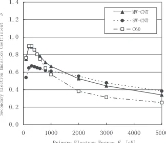
Fig. 2. Variation of secondary electron emission coefficient of carbon-nano-materials as a function of the primary electron energy.
������ Ep���������������� ����Ep����Ra�0.3 �m ��������� �������Ep��������������� ����������������������� ������ 3.4. ����� ��Au������Si�������� Al2O3�� �������200 nm ������������� ����������������������� ��������Fig. 4 ������������ ������������������������ ������������������������ ����������200 nm ���������� ������������������������ ������ 4. ��� ���������������������� ��(1)�������������������� ����������������(2)������ ����������������������� �������������(3)�� 200 nm ���� ������������������������ ������������������������ ����������������������� ���������������������� ������ ���1�����NIMS� ���������������������� ������������ ����1-1� ���������������������� ����������������������� ���������C60������������� ���CNT ������������������ ���� ���� �������2. .�������������� 1 ����������� ����1-2� Fig. 3 �������������������� ���Fig. 1, Fig. 2 ���Ep����������� ����������������������� ����������������������� ���������������������� ���� ������������������� Fig. 3 ������������C60, CNT ������� ������������������������ ������3.2. ������� 3 �������� ���������� ����������������������
Fig. 3. Variation of secondary electron emission coefficient of carbon plates as a function of the primary electron energy, measured Ra=~0.01 �m and 0.3 �m.
����������
Fig. 4.�Variation of secondary electron emission coefficient of carbon deposited on three substrates (Au, Si and Al2O3) and no
����1-3� �3.3. ������������������� ����500 �m�400 �m ������������ ������������������������ ����������������������� ����������������������� ������������� ���� ����������500 �m�400 �m ����� ����������������������� ���� ����1-4� �3.4. ������������� Al2O3��� ����������������������� ������Fig. 4 �� 100 V - 3 kV ������� ����������������������� ����������100 V ������ 5 kV �� ����������������������� ����������������������� ����������������������� ����������������� ���� Al2O3����Al �������������� 500 nm�����2. �������������� 1 ��������������� 100 V ���� ����������������������� ����������������������� ����������������������� ��� ���2����������� ���������������������� ����������������������� ������������������������ ����������������������� ����������������������� ����������������������� ����JSA ������������������ ����������������������� ����2-1� ����������������������� ����������������������� ����������������������� ����������������������� ��������������������� ����2-1-1������ HOPG���������or ������������ purity������ C60�SW-CNT�MW-CNT������������ ����������������������� ���������Purity ����� CNT ���� �SW-CNT ��������������� ���������purity������������ �RMS�������� ����������������������� ��������������� ����������or ������������ purity������� ���� ���������������������2. ��������������1 ��������� ����2-1-2��������� ���������������������� ������������������������ ����������������������� ������������� Ar �������� ������������������������ ����������������������� ����������������������� ������������������������ ���� Ar ���������������2. ���� ����������������������� ��1 ��������� ����2-2� �3.1. spn�������������Ep���� ������������������������ ����������������������� ������������������������ ���������������200 eV � 2000 eV �HOPG ������ 0.1 ������������ ����������������������� ����� 200 eV ��~20%��������� 2000 eV ���50�������������� HOPG ��� 3000 eV �������������� ����������������������� �������
���� ������������������Fig. 1 � Fig. 1(a)���Fig. 1(b)�������������� �������������������� ����2-3� ���� 2-1���������������� ����������������������� �����C60 � CNT ������������� CNT ����������SEM �������� ����������������������� ����������������������� ����������������������� �� ���� SEM �������������������� ����������������������� ����������������������� ����������������������� ����������������������� �������� ����2-4� �3.3. ������������������� ������������������������ �����RMS?�� 0.01 �m ������� eV � ����������������������� ������������������������ ����������������������� ����0.3 �m ���������������� ����������������������� ����������������������� ������������������������ ����������������������� ����������������������� ����������������������� 0.3 �m � 0.01 �m ����������� 50%�� ������������������ 2-3��� �����C60�CNT ������������� ������������������������ ���� ����������������������� � Ep��������������������� ���Ep������������������� ��������������������C60� CNT �������������������� ����������������������� ������������ ����2-5� �3.4. ���������� ����2-5-1��Al2O3������ ���������������������� ����������������������� ����������������������� ��������������������Al2O3 ������������2. ���������� ����������������������� ������ ���� Al2O3����Al �������������� 500 nm��������2. ������������ ��������� ����2-5-2��������� 200 nm ���� ��������� ���������������������� ����������������������� ��������200 nm ������������ ����������������200 nm ���� ����������������������� ����������������������� ������ ���� ���������������������� ����������������������� ������200 nm �������������� ������������������������ ����������������������� �����