A DFT Method for RTL Data Paths Achieving 100% Fault Efficiency
under Hierachical Test Environment
Hiroki Wada , Toshimitsu Masuzawa , Kewal K. Saluja and Hideo Fujiwara
Graduate School of Information Science, Nara Institute of Science and Technology, 8916-5 Takayama-cho, Ikoma-shi, Nara, 630-0101, Japan
Department of Electrical & Computer Engneering, University of Wisconsin-Madison 1415 Engneering Drive, Madison, WI 53706-1691,USA
Abstract– In this paper, we propose a DFT method for RTL data paths to achieve 100% fault efficiency. The DFT method is based on hierarchical test and usage of a combinational ATPG tool. The DFT method requires lower hardware overhead and shorter test generation time than the full scan method, and also improves test application time drastically compared with the full scan method.
Keyword– Design for testability,Data path, Hierarchical test, Complete fault efficiency
1 Introduction
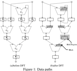
We propose a DFT method for RTL data paths suitable for a hierarchical testing. A data path treated in this paper is a concatenation of hardware elements and wires. Hardware el- ements are categorized in five kinds: primary inputs, primary outputs, registers, operational modules and multiplexers. Fig- ure 1(a) shows an example of those data paths. To simplify the problem, the followings are assumed:
(A1) An operational module has only one or two input ports and only one output port.
(A2) An operational module with one input port has a func- tion that is a bijection between its input and its output. (A3) An operational module with two inputs x and y has a
function that is a bijection between x (y) and its output port by fixing y (x) to a predetermined constant. That is, there are constants c and c such that both fy c x and fx c y are bijections, where fy c x and fx c y are the functions of the operational module when its inputs yand x are fixed to c and c , respectively.
In the hierarchical test, testing for each hardware element M proceeds as follows.
1. Test vectors are generated for M (a combinational cir- cuit) using a combinational ATPG tool.
2. The test vectors are applied to M: the values are fed through primary inputs at appropriate times, so that the desired test vectors can be applied to M.
3. The responses of M to the test vectors are propagated to primary outputs for observation.
To propagate the test vectors and the responses, some hard- ware elements must be controlled adequately. A test plan spec- ifies the control signals to propagate the test vectors and the responses.
Definition 1 A data path is strongly testable iff for each hard- ware element M, there exists a test plan that makes it possible to apply any vector to M and to observe any response of M.
The proposed DFT algorithm (in Section 2) converts an arbitrary data path to a strongly testable data path while keeping the extra hardware as low as possible.
A strongly testable data path has the following advantages. Fast test vector generation: Test vector generation time is short since a combinational ATPG tool can be used. Moreover, it is shorter than that of full scan, orthogonal scan[2] or H-SCAN[3] design, because the ATPG tool is applied to each hardware element separately and not to the whole circuit at once.
Fast test plan generation: Test plan generation time is
C1
C2 C3
C4
R7 R6 R5
R4 R3 R2 R1
Hold Register Mask
(a)before DFT (b)after DFT
Figure 1: Data paths
short since test plans are generated at RTL (not at gate level).
100% fault efficiency: 100% fault efficiency can be achieved for the whole circuit, since each hardware el- ement M is a combinational circuit of small size and strong testability guarantees complete controllability and complete observability of M.
Because the proposed algorithm can convert a data path without backtracking, the conversion time is shorter than that of Genesis[4].
2 DFT for strong testability
In our DFT method, we add no special path for propagating test vectors and responses. Instead, test vectors and responses will be propagated along existing paths.
Consider testing of an embedded hardware element M with two input ports, x and y, in the data path. To test M, a value specified by a test vector should be fed into input port x. We propagate the value along a path p from a primary input a to x. If an operational module C appears in p, the output value of C will depend on the function of C and its input value(s). However, assumption (A2) guarantees that the output of C is completely controllable by its input if C has only one input port. Similarly, for an operationai module C with two input ports, assumption (A3) guarantees that the output of C is completely controllable by one input if the other input is fixed to a constant value. To apply such a constant, in our DFT method, a mask elementis added to the input port. We add the mask element to every two-input operational module C in path p so that its input port appearing in p can control its output port. Thus, using the mask elements, input port x (the terminal node of p) can be completely controlled from primary input a (the start node of p).
However, we cannot always achieve the strong testability only by adding the mask elements. The mask elements guar-
1
IEEE European Test Workshop, May 1999
antee controllability of a single path. Presence of reconvergent paths in a data path can prevent application of a desired input to a two-input module. In particular, this can happen if the paths for propagating the values start from the same primary input and have the same sequential depth. Such reconvergence of paths will cause a timing conflict, i.e. two different values at a primary input at the same time. To resolve such conflicts, in our DFT method, certain registers are augmented with hold function.
The heuristic algorithm for the DFT insertion proceeds in three stages consisting of generation of graph models (stages 1 and 2)and insertion of DFT elements (stage 3). (Stage 1) Construct a control forest: To determine paths to propagate test vectors, we construct a control forest. The control forest is a spanning out-forest1of the port digraph where primary inputs are roots, and its paths are used to propagate test vectors. (Stage 2) Construct an observation forest: To determine paths to propagate responses, we construct an observation forest. The observation forest is a spanning in-forest2of the port digraph where primary outputs are roots, and its paths are used to prop- agate responses.
(Stage 3) Add DFT elements: To make the data path strongly testable, we add DFT elements (mask elements and hold func- tion) to the data path at strategic locations. See Figure1(b).
The computation time of the above algorithm is n where nis the number of hardware elements in a given data path.
We also propose a test plan generation algorithm for the data path obtained by the DFT algorithm. The test plan gen- eration algorithm can generate for all modules in a data path without backtracking. The time complexity of the algorithm is n2 . The algorithm is not presented in this paper due to space limitation. For details, see [1].
3 Experimental results
We applied our method to three benchmarks: GCD, 4th IIR, and Paulin. Tables 1, 2 and 3 summarize the experimental results. To evaluate the effectiveness of our method, we com- pare it with the full scan method. In the experiments, gate-level implementation of each of the three data paths is generated us- ing a logic synthesis tool AutoLogicII (Mentor Graphics Co.), and test vectors are generated using a combinational ATPG tool TestGen (Sunrise Test System Inc.) on a SUN SPARC Station- 20 (SuperSPARC 75MHz).
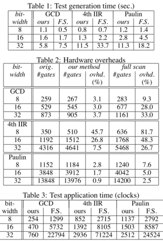
We achieved 100% fault efficiency for all circuits, using our method as well as the full scan method. Table 1 shows the test generation time. In this table column bitwidth denotes the width of the data paths considered in our experimantal study. Three different widths were considered. Columns ours and F.S. show test generation time for designs using our method and full scan method respectively. The test generation time for our method includes CPU time of our DFT algorithm (in Section 2) and the test plan generation algorithm (not described in this paper) in addition to the total test generation time for all hard- ware elements. The time for the DFT and the test plan gen- eration was 0.2 seconds for each of three data paths. Notice that the CPU time for these algorithm does not depend on the bitwidth since the algorithms work on RTL data paths. Advan- tage of hierarchical testing can be further argued as follows. While ATPG in full scan designs is executed for the complete data path at once, ATPG in our method is executed for each hardware element separately. Thus, our method offers greater advantage as the size of a data path becomes larger.
1A directed forest in which each port is reachable from some primary input. 2A directed forest in which there is path from each port to some primary output.
Table 1: Test generation time (sec.)
bit- GCD 4th IIR Paulin
width ours F.S. ours F.S. ours F.S.
8 1.1 0.5 0.8 0.7 1.2 1.4
16 1.6 1.7 1.3 2.2 2.8 4.5
32 5.8 7.5 11.5 33.7 11.3 18.2 Table 2: Hardware overheads bit- orig. our method full scan width #gates #gates ovhd. #gates ovhd.
(%) (%)
GCD
8 259 267 3.1 283 9.3
16 529 545 3.0 677 28.0
32 873 905 3.7 1161 33.0
4th IIR
8 350 510 45.7 636 81.7
16 1192 1512 26.8 1768 48.3
32 4316 4641 7.5 5468 26.7
Paulin
8 1152 1184 2.8 1240 7.6
16 3848 3912 1.7 4042 5.0
32 13848 13976 0.9 14200 2.5
Table 3: Test application time (clocks)
bit- GCD 4th IIR Paulin
width ours F.S. ours F.S. ours F.S.
8 254 1299 852 2715 1137 2792
16 470 5732 1392 8105 1503 8587
32 760 22794 2936 71224 2512 24524
Table 2 shows hardware overhead of the DFT methods. Column orig. lists the number of gates in circuits generated from the original data paths. Column our method and F.S. con- tain the number of gates in circuits generated from the data paths after modification by the DFT methods. In all examples, our DFT method has lower hardware overhead (ovhd.) than the full scan method.
Table 3 shows test application time for the data paths. We determined the time by the number of clocks required to ap- ply all the generated test vectors and to observe the responses. Our method improves test application time drastically com- pared with the full scan method.
Acknowledgment This work was supported in part by Semi- conductor Technology Academic Research Center (STARC) un- der the Research Project and in part by the Ministry of Educa- tion, Science, Sports and Culture, Japan under the Grant-in-Aid for Scientific Research B(2) (No.09480054).
References
[1] T. Masuzawa, H. Wada, K. K. Saluja and H. Fujiwara: “ A non-scan DFT method for RTL data paths to archieve complete fault efficiency,” Information Science Technical Report:TR98009, Nara Institute of Science and Technol- ogy, 1998
[2] R.B.Norwood and E.J.McCluskey: “Orthogonal scan: Low overhead scan for data paths”, Proc. 1996 Int. Test Conf. ,pp.659-668 ,1996
[3] S. Bhattacharya and S. Dey: “A high-level alternative to full-scan testing with reduced area and test application time,”Proc. the IEEE VLSI Test Sympo.,pp.74-80,1996 [4] S.Bhatia and N.K.Jha: “Genesis: A behavioral synthesis
system for hierarchical testability,” Proc. European Design and Test Conference , pp272 -276 , 1994
2