A Binding Method for Hierarchical Testing
Using the Results of Test Environment Generation
Hiroaki FUJIWARA
†Toshinori HOSOKAWA
‡Ryoichi INOUE
†Hideo FUJIWARA
†††Graduate School of Industrial Technology, Nihon University, 1-2-1 Izumicho, Narashino, Chiba 275-8575, Japan
‡College of Industrial Technology, Nihon University, 1-2-1 Izumicho, Narashino, Chiba 275-8575, Japan
††Faculty of Informatics, Osaka Gakuin University, 2-36-1 Kishibe-Minami, Suita-shi, Osaka, Japan
E-mail: †[email protected], ††[email protected],
‡[email protected], ‡‡[email protected]
Abstract The recent advances in semiconductor technology have resulted in an exponential increase in VLSI circuit density and complexity. Therefore, it is difficult to generate test sequences for sequential circuits using gate-level sequential ATPGs. Hierarchical test generation methods that generate test environments for each functional element at the functional register transfer level and test patterns for each combinational module at the gate level have been proposed to accelerate sequential test generation. In this paper, we propose a binding for testability method that preferentially assigns operations with test environments and operations without test environments to the same operational unit to reduce the number of hard-to-test operational units. The experimental results show the effectiveness of the proposed method.
Keywords hierarchical test generation, behavioral synthesis, test environment, binding for testability, functional register transfer level
1. Introduction
The recent advances in semiconductor technology have resulted in an exponential increase in very-large-scale integration (VLSI) circuit density and complexity. Effective and efficient test generation algorithms for combinational circuits have been proposed. These algorithms can achieve high fault efficiency even for large circuits [1-5]. However, it is very difficult to achieve high fault efficiency for sequential circuits in a reasonable test generation time by a conventional gate-level sequential automatic test pattern generator (ATPG).
Generally, the current large-scale integrated circuits (LSI) design flow starts from the register transfer level
(RTL) design. Design productivity decreases as LSI design costs increase [6]. Therefore, a new design methodology that uses behavioral synthesis to describe the LSI behavior and synthesize RTL circuits is gathering attention.
Because the amount of LSI behavioral descriptions is less than that of RTL descriptions, designing at the behavioral level can improve design productivity. Because behavioral synthesis assigns resources such as registers and operational units, the synthesis performance greatly influences the performance of the synthesized circuits [6].
Behavioral synthesis primarily performs scheduling [6] and binding [6]. Scheduling assigns execution times to operations and binding assigns registers and operation units to variables and operations. Synthesized cycle-accurate circuits after scheduling are said to be functional RTL circuits. Synthesized circuits after scheduling and binding are said to be structural RTL circuits. Functional RTL circuits and structural RTL circuits are synthesized to gate-level circuits by logic synthesis.
Several design-for-testability (DFT) methods based on hierarchical test generation [7] for structural RTL circuits have been proposed [8-10]. In references [8-10], a structural RTL circuit consists of a data-path part and a controller part, both of which are isolated in the test modes. Separate DFT methods have been proposed for the data-path part and the controller part. Therefore, the area overhead for testing becomes larger. Hierarchical test generation methods for a stuck-at fault model for functional RTL circuits have been also proposed [11-13]. In these methods, a given functional RTL circuit is first described in an assignment decision diagram (ADD) [14]. Then, test environments are generated for each
operation. A test sequence is formed by substituting the corresponding test patterns of the gate-level circuit to the operation in the test environments. Compared with a gate-level ATPG, these methods can drastically reduce the test generation time without sacrificing fault coverage [11-13]. These methods perform binding by logic synthesis. Therefore, if the test environment coverage, which is the ratio of the number of nodes successfully generating test environments to the total number of nodes, is low, it is not guaranteed that the generated test sequences can achieve high fault coverage. In this paper, we propose a binding for testability method that preferentially assigns operations with test environments and operations without test environments to the same operational unit to reduce the number of hard-to-test operational module units.
The outline of this paper is as follows. Section 2 explains ADD. Section 3 describes behavioral synthesis. Section 4 describes hierarchical test generation. In Section 5, a binding for testability method is proposed. The experimental results are shown in Section 6. Finally, Section 7 concludes this paper.
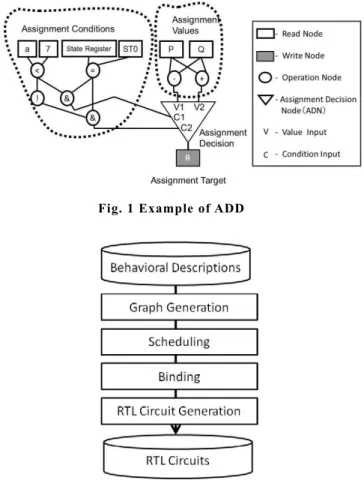
Fig. 1 Example of ADD
Fig. 2 Flow of behavioral synthesis
2. Assignment Decision Diagram
An ADD is an acyclic graph that consists of a set of nodes categorized into the following four types: read node, write node, operation node, and assignment decision node (ADN), as shown in Fig. 1. In addition, the ADD has a set of edges containing the connectivity information between two nodes. (Fig. 1). The read node represents a primary input port, a storage unit, or a constant. The write node represents a primary output port or a storage unit. The operation node expresses an arithmetic operation unit or a logic operation unit, and the ADN selects a value from a set of values provided to it based on the conditions computed by the logic operation units. If one of the condition inputs becomes true, the value of the corresponding data input is selected. Although ADD was essentially introduced as an internal representation in the behavioral synthesis process, it can be used to describe a functional RTL circuit, the controller part and the data-path part, which are homogeneously represented.
3. Behavioral Synthesis
Behavioral synthesis generates RTL circuits using hardware description languages such as VHDL and Verilog-HDL from behavioral descriptions using, for example, C language and System C. Behavioral synthesis consists of four steps: graph generation, scheduling, binding, and RTL circuit generation, as shown in Fig. 2. In the graph generation step, graphs such as the ADD [14] or the Control/Data-Flow Graph (CDFG) [6] are generated from the given behavioral descriptions. In the scheduling step, each operation is assigned to a time slot corresponding to a clock cycle or time interval. In the binding step, operational units (hardware components) and registers are assigned to operations and variables, respectively. In the RTL circuit generation step, the data-path part and the controller part are generated.
In behavioral synthesis using ADD, for example, scheduling and binding are implemented by transforming the graph structures. In this paper, an ADD after scheduling is said to be a functional ADD, and an ADD after binding is said to be a structural ADD.
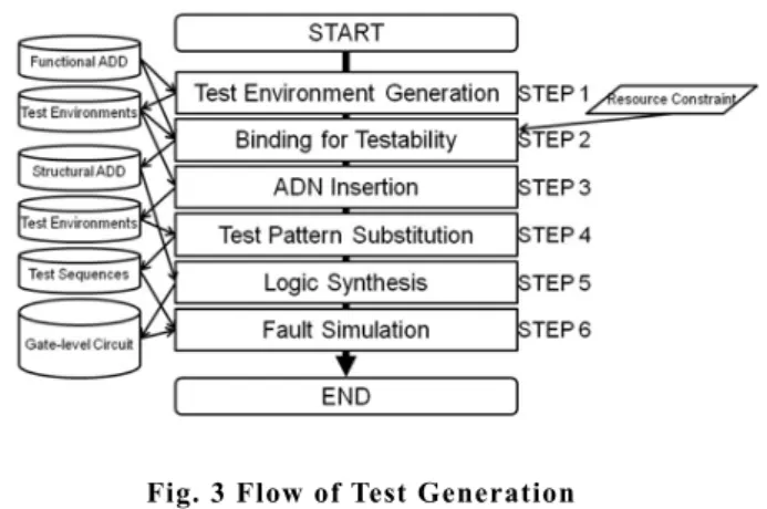
Fig. 3 Flow of Test Generation
4. Hierarchical Test Generation Based on a
Functional ADD
4.1. Test Environment Generation
Hierarchical test generation for a functional ADD (i.e., after scheduling) is explained as follows. When a node N is being tested, the testability of the node is guaranteed if any value can be propagated from a read node corresponding to a primary input port to the input of N, and the value at the output of N can be propagated to a write node corresponding to a primary output port. The path allowing any value to be propagated from a read node corresponding to a primary input port to the input of N is called a justification path, and the path allowing the value at the output of N to be propagated to a write node corresponding to a primary output port is called the propagation path. In this paper, justification and propagation are done through symbolic processing that utilizes 9-valued algebra [11]. The series of symbols obtained from the symbolic processing that activates justification and propagation paths is known as the test environment for the node under test. For a given node under test, its test sequence is generated by first extracting a test pattern from the test set library and substituting the test pattern for the test environment. The test set library is obtained beforehand by first taking a gate-level circuit whose functionality is the same as that of the node under test, then generating the test patterns for all faults in the circuit using a combinational ATPG algorithm. In the case that the node is synthesized to a different circuit, fault simulation must be performed to check the fault
efficiency of the test patterns.
4.2. Problem of Hierarchical Test
Generation Based on a Functional ADD
If the test environment coverage [12-13], which is the ratio of the number of nodes successfully generating the test environments to the total number of nodes, is high, fault coverage at the gate level is also high. However, high fault coverage is not necessarily obtained compared to gate-level sequential ATPG methods, even if hierarchical test generation methods [11-13] are used. The reason is described as follows. In references [11-13], binding processing was not taken into account. The binding processing of logic synthesis may assign operation nodes with no test environments generated for the same operational unit. In this case, the operational unit does not have test environments. Therefore, we consider that because faults in the operational unit are not detected by the generated test sequences, fault coverage is not high. To resolve this problem, we propose a binding for testability method which preferentially assigns operations with test environments and operations without test environments to the same operational unit.
5. Binding for Testability
5.1. Test Design Flow
The procedure of the proposed test generation is explained. The flow of the test generation is shown in Fig. 3.
(STEP 1) Test environments are generated for a given functional ADD by the method shown in reference [11].
(STEP 2) The binding for testability is performed for a functional ADD under the constraint of the number of operational units. The binding for testability method is described in Section 5.3 in detail. A structural ADD is generated by the binding.
(STEP 3) ADNs are inserted into an ADD when the binding is performed for a functional ADD. Therefore, test environments for the inserted ADNs are generated. (STEP 4) Test sequences are generated by first extracting test patterns from a test set library and by substituting these test patterns for the test environments.
(STEP 5) Logic synthesis is performed for the structural ADD generated in STEP 2 and a gate-level circuit is
generated.
(STEP 6) Fault simulation is performed for the gate-level circuit by the test sequences generated in STEP 4, and the fault coverage is calculated.
5.2. Problem Formulation
(Definition 1: Functional RTL test environment coverage)
all TE
F
N
RTE N
#
#
Functional RTL test environment coverage (RTEF) is defined as the ratio of the number of nodes successfully generating test environments (#NT E) to the total number of nodes under test in a functional ADD (#Nal l). In this paper, the nodes under test are only the operation nodes. (Definition 2: Structural RTL test environment coverage)
all TE S
M
RTE M
#
#
Structural RTL test environment coverage (RTES) is defined as the ratio of the number of modules successfully generating test environments (#MT E) to the total number of modules under test in a structural ADD
(#Ma l l). In this paper, the modules under test are only
the operational units. (Problem formulation)
Inputs: Nodes under test in a functional ADD (e1, …, en), where n is the number of nodes under test and each node has the information of whether a test environment is generated.
Outputs: The binding information for each module (B1,
…, Bm), where m is the number of modules and each binding information has assigned nodes.
Optimization: Maximize the structural test environment coverage.
Constraint: The number of operational units.
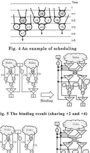
Fig. 4 An example of scheduling
Fig. 5 The binding result (sharing +2 and +4)
Fig. 6 The binding result (sharing +2 and +7)
Fig. 7 Binding for testability algorithm
5.3. Binding for Testability Algorithm
The proposed binding algorithm for testability is explained using an example. Fig. 4 shows a scheduling example. Fig. 5 shows the binding results in which the add operation nodes +2 and +4 are assigned to the same adder unit for Fig. 4. Fig. 6 shows the binding results in which the add operation nodes +2 and +7 are assigned to the same adder unit for Fig. 4. In the test environment generations for +2 and +4 of Fig. 4, because the symbol for fault effects O [11] cannot be propagated to the outputs of the multiplier nodes *1 and*2, the test environments cannot be generated. The test environment for +7 can be generated. When +2 and +4 are assigned to the same adder unit, the test environment of the adder unit does not exist and the adder unit cannot be tested (Fig. 5). In contrast, when +2 and +7 are assigned to the same adder unit, the test environment of the adder unit exists and the adder unit can be tested. In this paper, we propose a binding for testability method which preferentially assigns operations with test environments and operations without test environments to the same operational unit. Our goal is to improve structural test environment coverage while satisfying the resource constraints.
Fig. 7 shows the algorithm of binding for testability. Explanations for each line of code are given in the following.
(line 1) An operation set OP is given. The elements of the OP are operation nodes. Each operation node has the information of whether a test environment has been generated.
(line 2) Lines 3 to 9 are iterated for each operation Ni with a test environment.
(line 3) Lines 4 to 8 are iterated for each operation Nj
without a test environment.
(line 4) If Ni and Nj are able to be merged, lines 5 to 8 are performed.
(line 5) Ni and Nj are merged to a new operation Nn e w. (line 6) Nn e w is added to the OP.
(line 7) Ni and Nj are deleted from the OP. (line 8) The algorithm returns to line 2.
(line 12) Lines 13 to 19 are iterated for each operation Ni in the OP.
(line 13) Lines 14 to 18 are iterated for each operation Nj except Ni.
(line 14) If Ni and Nj are able to be merged, lines 15 to 18 are performed.
(line 15) Ni and Nj are merged to a new operation Nn e w.
(line 16) Nn e w is added to the OP.
(line 17) Ni and Nj are deleted from the OP. (line 18) The algorithm returns to line 12.
(line 22) Each node in the OP is assigned to an operational unit.
6. Experimental Results
The test environments and the test sequences using the method shown in reference [11] were generated for Paulin, Diffeq, and DCT, which are functional RTL circuits. The binding for testability method proposed in this paper was applied to the circuits. For comparison, the left-edge algorithm (LEA) [15] was also applied to the circuits.
Table 1 shows the results of the test environment generation. In Table 1, “Circuits” denotes the names of the circuits, “With TE” denotes the operation nodes with test environments, and “Without TE” denotes the operation nodes without test environments. Table 2 shows the results of the two algorithms for binding the circuits. In Table 2, “Operations” denotes the types of operational units, “Proposed” denotes the names of the operation nodes assigned to the operational units using the proposed binding method, and “LEA” denotes the names of the operation nodes assigned to the operational units using the LEA. Table 3 shows the functional RTL test environment coverage (“RTEF”) and the structural RTL test environment coverage (“RTES”). In Table 3, “Proposed” denotes the structural test environment coverage using the proposed binding method, and “LEA” denotes the structural test environment coverage using the LEA. The functional RTL test environment coverage was 70% to 76%. The structural RTL test environment coverage using the proposed binding method was 100%. In contrast, the structural test environment coverage using the LEA was only 75% to 80%.
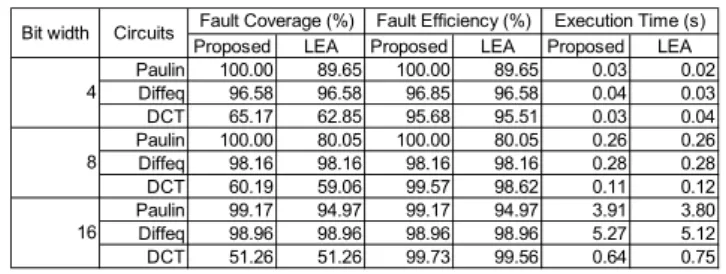
After the test sequence generation and binding, the gate-level circuits were generated by logic synthesis. Fault simulations for single stuck-at faults in only the operational units were performed for the gate-level circuits by the generated test sequences. Table 4 shows the fault coverage, the execution time for the fault simulation, and the fault efficiency. In Table 4, “Bit width” denotes the bit widths of the data path in the circuits, and “Execution Time” denotes the execution time for the fault simulation. Untestable faults were
identified using the gate-level sequential test generation tool “TetraMAXT M” from Synopsys. Thus, the fault efficiencies were calculated.
The fault coverage for the circuits generated by our proposed binding method increased by 4.22% on average compared with that generated by the LEA. The proposed binding for testability method effectively improved the structural test environment coverage and the fault coverage.
The fault coverage for DCT was low compared with that of the other circuits. Because DCT has many multipliers with constant input, many untestable faults in the gate-level circuit were identified by the TetraMAX ATPG.
Table 1 Experimental Results of Test Environment Generation
Table 2 Experimental Results of Binding
Table 3 Experimental Results of Test Environments Coverage
Table 4 Experimental Results of Fault Coverage
7. Conclusion
In this paper, we proposed a binding for testability method which preferentially assigns operations with test environments and operations without test environments to the same operational unit to improve the structural test environment coverage. The experimental results showed that both the structural test environment coverage and the fault coverage of the proposed binding method increased compared with those of LEA without considering the test environment. In future work, register binding for hierarchical testability will be examined.
References
[1] M. Schulz, E. Trischler and T. Sarfert, "SOCRATES: A Highly Efficient Automatic Test Pattern Generation System," IEEE Trans. on Computer-Aided Design, Vol. 7, No. 1, pp. 126-137, Jan. 1988.
[2] W. Kunz and D. Pradhan, "Recursive Learning: An Attractive Alternative to the Decision Tree for Test Generation in Digital Circuits," in Proc. IEEE International Test Conference on Discover the New World of Test and Design, pp. 816-825, 1992.
[3] M. Henftling, H. C. Wittmann and K. J. Antreich, "A Single-Path-Oriented Fault-Effect Propagation in Digital Circuits Considering Multiple-Path Sensitization," in Proc. 1995 IEEE/ACM International Conference on Computer-Aided Design, pp. 304-309, 1995.
[4] C. Wang, S. Reddy, I. Pomeranz, X. Lin and J. Rajski,
"Conflict Driven Techniques for Improving Deterministic Test Pattern Generation," in Proc. IEEE International Conference on Computer-Aided Design, pp. 87-93, 2002.
[5] E. Gizdarski and H. Fujiwara, "SPIRIT: A Highly Robust Combinational Test Generation Algorithm," IEEE Trans. on Computer Aided Design for Integrated Circuits and Systems, Vol. 21, No. 12, pp. 1446-1458, Dec. 2002.
[6] D. D. Gajski, N. D. Dutt, A. C-H Wu and S. Y-L Lin, HIGH-LEVEL SYNTHESIS: Introduction to Chip and System Design, Kluwer Academic Publisher, 1992. [7] B. T. Murray and J. P. Hayes, "Hierarchical Test
Generation Using Pre Computed Tests for Modules," IEEE Trans. Computer-Aided Design, Integrated Circuits & Syst., Vol. 9, No. 6, pp. 594-603, Jun. 1990. [8] I. Ghosh, A. Raghunathan and N. K. Jha, "Design for
Hierarchical Testability of RTL Circuits Obtained by
Circuits With TE Without TE
Paulin
Diffeq
DCT
+1, +2, -2, *1, *2, *4, *6
+1, +2, -2, *1, *2, *4, *6, <
+1, +2, +3, -1, -2, *1, *2, *3, *4, *5
-1, *3, *5
-1, *3, *5
+4, +5, +6
Circuits Operations Proposed LEA
MUL1 *3,*6 *3,*5
MUL2 *1,*2,*4,*5 *1,*2,*4,*6
ADD +1,+2 +1,+2
SUB -1,-2 -1,-2
MUL1 *4,*5 *3,*5
MUL2 *1,*2,*3,*5 *1,*2,*4,*6
ADD +1,+2 +1,+2
SUB -1,-2 -1,-2
LES < <
MUL1 *1,*2,*3 *1,*2,*3
MUL2 *4,*5 *4,*5
ADD1 +1,+3,+4,+6 +1,+3,+3,+5
ADD2 +2,+5 +4,+6
SUB -1,-2 -1,-2
Paulin
Diffeq
DCT
Proposed LEA
Paulin 70.00 (7/10) 100.00 (4/4) 75.00 (3/4) Diffeq 72.73 (8/11) 100.00 (5/5) 80.00 (4/5) DCT 76.92 (10/13) 100.00 (5/5) 80.00 (4/5) Circuits RTEF (%)
RTES (%)
Proposed LEA Proposed LEA Proposed LEA
Paulin 100.00 89.65 100.00 89.65 0.03 0.02
Diffeq 96.58 96.58 96.85 96.58 0.04 0.03
DCT 65.17 62.85 95.68 95.51 0.03 0.04
Paulin 100.00 80.05 100.00 80.05 0.26 0.26
Diffeq 98.16 98.16 98.16 98.16 0.28 0.28
DCT 60.19 59.06 99.57 98.62 0.11 0.12
Paulin 99.17 94.97 99.17 94.97 3.91 3.80
Diffeq 98.96 98.96 98.96 98.96 5.27 5.12
DCT 51.26 51.26 99.73 99.56 0.64 0.75
Fault Efficiency (%)
Fault Coverage (%) Execution Time (s)
Bit width Circuits 4
8
16
Behavioral Synthesis," IEEE Trans. Computer-Aided Design for Integrated Circuits and Systems, Vol. 16, pp. 1001-1014, Sep. 1997.
[9] S. Ohtake, T. Masuzawa and H. Fujiwara, "A Non-scan Approach to DFT for Controllers Achieving 100% Fault Efficiency," Journal of Electronic Testing: Theory and Applications (JETTA), Vol. 16, No. 5, pp. 553-566, Oct. 2000.
[10] H. Wada, T. Masuzawa, K. K. Saluja and H. Fujiwara,
"Design for Strong Testability of RTL Data Paths to Provide Complete Fault Efficiency," in Proc. of 13th International Conf. on VLSI Design, pp. 300-305, Jan. 2000.
[11] I. Ghosh and M. Fujita, "Automatic Test Pattern Generation for Functional RTL Circuits Using Assignment Decision Diagrams," in Proc. of ACM/IEEE Design Automation Conference, pp. 43-48, Jun. 2000. [12] L. Zhang, I. Gosh and M. Hsiao, "Efficient Sequential
ATPG for Functional RTL Circuits," in Proc. International Test Conference, pp. 290-298, Sep. 2003. [13] H. Fujiwara, C. Y. Ooi and Y. Shimizu, "Enhancement of
Test Environment Generation for Assignment Decision Diagrams," 9th IEEE Workshop on RTL and High Level Testing (WRTLT'08), pp. 45-50, Nov. 2008.
[14] V. Chaiyakul, D. D. Gajski and L. Ramachandran,
"High-Level Transformations for Minimizing Syntactic Variances," in Proc. Design Automation Conference, pp. 413-428, Jun. 1993.
[15] F. J. Kurdahi and A. C. Parker, “REAL: A Program for Register Allocation,” in Proc. Design Automation Conference, pp. 210-215, Jun. 1987.