1 | P a g e
Diodes
- Consist of two doped semiconductor - Joining of one n-type and one p-type
semiconductor
- When two semiconductors are brought together, electrons will transfer from N to P (filling up of
͞holes͟)
- If there is a depletion junction, the electrons will require energy to cross the junction - When the diodes are connected in FORWARD BIAS, it will
lower the potential barriers between the junction and pushes free electrons across the barrier.
- IV curve of diode is as shown,
o When it is in forward bias, the current increases exponentially
o In reverse bias, the current will drop to very small until the breakdown voltage, a LARGE NEGATIVE CURRENT is produced.
Diode Equation
iD = Is e
vD nVT− 1
Where VT = kT
q
k = 1.38 × 10⁻²³JK−1(Boltzman s constant) q = 1.6 × 10⁻¹⁹C
n= 1 (In this course), n is an integer constant which depends on the fabrication of the diode
Zener diodes
Zener diode is designed to function in reverse biased mode, their breakdown characteristics is deliberately made to be as vertical on the IV curve as possible.
- Act to provide constant voltages in a circuit
- Diode is made to breakdown at a certain voltage, which is known as Zener voltage VZ
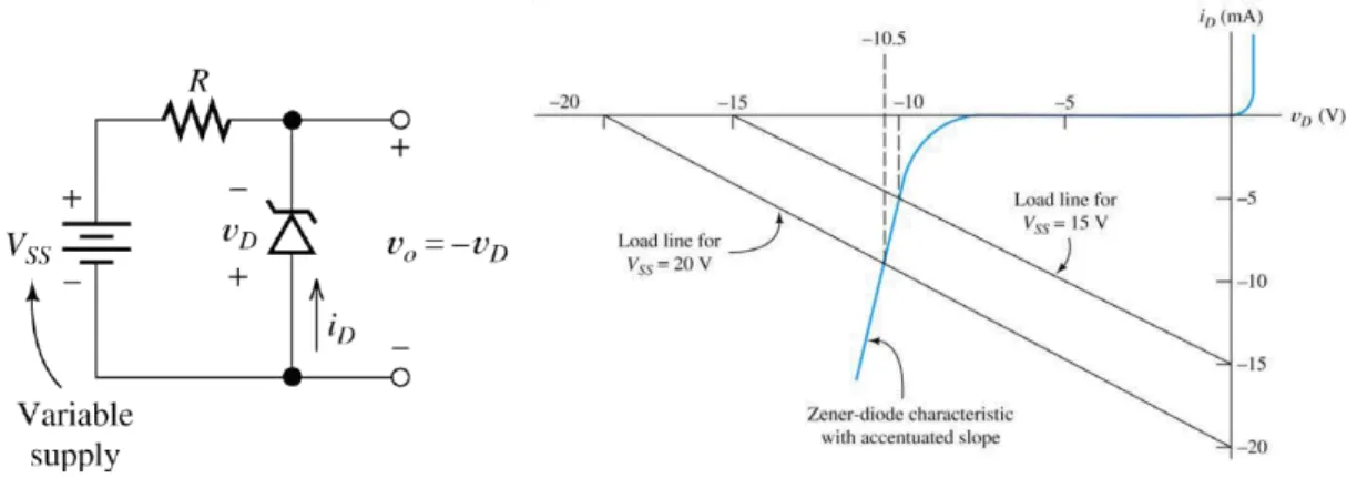
Load-line Analysis
- Intersection point of both graphs = operating point - Apart from that, we should also check the maximum
diode current or maximum power dissipation of the diode is NOT EXCEEDED!
2 | P a g e
- Load line technique can also be used to predict the behaviour of Zener diode too
Offset Voltage
- An offset voltage of 0.6 V is usually used
- If vD 0.6V, consider it to be short circuit but having a fixed 0.6 V drop - If VZ < vD < 0.6�, consider the diode to be open circuit
- If vD < VZ, consider the diode current to be VZ
Rectifier Circuits
Half-Wave Rectifier
- When a diode is connected to an AC source, a half wave rectifier is constructed
- Since we know that the diode will make a potential drop of 0.6 V, we also observe the rectified voltage to be 0.6V less than the real value.
- This can be applied to a battery charger circuit
Smoothing Capacitor
- During the conversion of AC to DC, a smoothing capacitor should be used to minimize the varying values of the rectified voltage
- When a capacitor is connected to a diode circuit, during the increasing of voltage value, the capacitor will be charged at the same time to the peak voltage - When the diode is in reverse bias, the capacitor starts
to supply current to the load until the next positive half cycle
- When the capacitor is discharging, this creates the ripple voltage Vr (as SMALL as possible)
- To analyse the output, we assume that the capacitor discharges in a full period of time, T (period of the AC source!!) and the load current is approximately constant (The current ripple is small – See the
diagram in the NEXT PAGE)
3 | P a g e
∆Q = C × ∆V = iLT
Since, ∆V = Vr,
=���
��
The output DC voltage will be assumed to be about
Vr 2
- When dealing with questions involving half wave rectifier, remember:
o Take the peak AC voltage as (For all half/full wave rectifier)
o When applying the capacitor equation, remember use the Vr as the ripple voltage value and take the time T as the period of the AC supply voltage.
- The capacitor in most cases are large (mF range)
Full Wave Rectifier
- Full wave rectifier can give the result at which there is NO gap between the rectified voltage
- The analysis of the problem are still the same, the only differences are: o Take note that the discharging
time now is �
o The equation of the capacitor is
= ���
��
Smoothing Filters
- To further refine the smoothing action and to reduce the ripple voltage, a FILTER can be used - A low-pass filter is used
- The capacitance of C is made to be small impedance at ripple frequency compared to R and RL i.e. X RL since RL R
Peak AC Voltage= supply to load + offset voltage of diode(s) + ripple voltage
connected
4 | P a g e
- To analyse AC effect, the output ripple voltage Vro is
Vro = jX R + jXVr Vro
Vr = X R2+ X2 - For DC part, VD is analysed
VL = RL R + RL���
- That is why we want to make the amplitude of initial signal larger in order to obtain the desired output DC value
Voltage Regulator
- Zener diode is used because it can provide constant voltage
- Unregulated source passes through the RS, which limits the current and then pass through Zener diode - The output voltage is then being regulated to VZ.
- As long as the Zener diode holds some current, it will fix the output voltage to VZ, so the load current is iL = VZ
RL - The load current iL : iL = iS− iZ
- Using Kirchoff s Voltage law, we can see that the limiting current iS is: vs = iSRS+ VZ
- The Zener diode will be able to regulate the circuit by keeping the output voltage as constant as long as: o It has a minimum current for it to operate
o Does not exceed the power rating
- The load resistance cannot be so small that the Zener diode current becomes zero!
- The load resistance also cannot be too large that the Zener diode exceeds its power rating! PROBLEM ANALYSIS
When approach to a problem of Smoothing RC filter, the following should be taken note: - Find the capacitive impedance
- Find the filtered ripple voltage
- If load resistance is given, then the output DC voltage can be determined
5 | P a g e
Diode small signal Analysis
- Diode is a voltage driven device
- The type of current flow through the diode is dependent on the potential applied across it - In an input supply of both AC and DC, the equation can be
written as
VS ω = VD+ vdcos(ωt)
- When voltage increases, the current increases (since the IV curve of diode is increasing exponentially)
- We can determine the AC resistance from the Q point (operating point) of the diode
- After that, we can replace the diode with an effective resistance rd and then we can analyse AC and DC separately
- Assumption: The AC change is small - To find the AC resistance,
Assume: iD ≈ IS e
v D n V T
diD dvD =
1 nVT �� �
��
��� = ��
���
�� =��� �=��� �
�
- Since the AC signal is much smaller than the DC value, we replace iD = IDQ(The actual DC current) - Important points:
o In AC equivalent circuits, DC is assumed to be connected to the ground point. This is because the voltage does not change.
o If the impedance of the capacitor is small enough to neglect, just do so.
- This analysis can aid us into the application of Voltage controlled attenuator at which the DC voltage change will influence the output voltage of the entire circuit
- This can be used as automatic controlling the recording volume of microphone PROBLEM ANALYSIS
When dealing with problems involving AC and DC sources in a diode circuit, the following should be carried out:
- Analyse the circuit with only DC source - Find the DC current IDQ by assuming vd=0.6 V - Find the AC resistance ��
- Analyse circuit with only AC source, ground the DC supply and replace the diode with rd
- Solve for vVo
S