D ir e ct e d I n spe ct ion a n d
M a in t e n a n ce Le a k Su r v e y a t a
Ga s Fr a ct ion a t ion Pla n t Usin g
Tr a dit ion a l M e t h ods a n d
Opt ica l Ga s I m a gin g
Dave Picar d, Clear st one Engineer ing Lt d.;
Jeff Panek, I nnovat ive Envir onm ent al Solut ions I nc.;
Dave Fashim paur , BP
Out line of Pr esent at ion
1.0 I NTRODUCTI ON
1.1
Facilit y Descr ipt ion
1.2
Obj ect ives
2.0 METHODOLOGY
2.1
Em issions Sur vey
3.0 OVERVI EW OF THE EMI SSI ONS
3.1
Em issions I nvent or y
3.2
Aver age Com ponent Em ission Rat es
3.3
Sit e- Specific Em ission Fact or s
4.0 EMI SSI ON REDUCTI ON OPPORTUNI TI ES
4.1
Fugit ive Equipm ent Leaks
5.0 LEAK DETECTI ON METHODOLOGY COMPARI SON
I nt r oduct ion
I nt r oduct ion
1.2 Obj ect iv es
Pr im ar y obj ect ive –
t o ident ify and m easur e hydr ocar bon
em issions fr om fugit ive equipm ent leaks
and highlight pot ent ial cost - effect ive
em issions r educt ion oppor t unit ies.
Secondar y obj ect ive –
t o com pare t he over all per for m ance of
t he Haw k passive I R cam er a opt ical gas
im aging m et hod t o convent ional leak
Met hodology
2.1 Em issions Sur vey: m ain elem ent s
scr e e n in g of e qu ipm e n t com pon e n t s t o
de t e ct le a k s,
m e a su r e m e n t of e m ission r a t e s fr om ident ified
leaking equipm ent com ponent s ( i.e., leaker s) ,
m e a su r e m e n t of e m ission s fr om con t in u ou s
v e n t s and r esidual flow s fr om em er gency vent s
dur ing passive per iods,
de v e lopin g cou n t s of t he sur veyed equipm ent
com ponent s,
de v e lopm e n t of t h e e m ission s in v e n t or y ,
de t e r m in a t ion of sit e - spe cific a v e r a ge
e m ission fa ct or s for fugit ive equipm ent leaks,
and
cost - be n e fit a n a ly sis of t he ident ified cont r ol
Met hodology
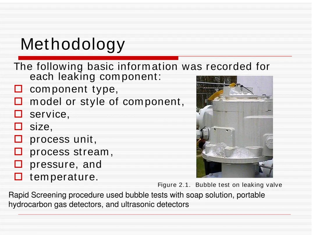
The follow ing basic infor m at ion w as r ecor ded for
each leak ing com ponent :
com ponent t y pe,
m odel or st y le of com ponent ,
ser vice,
size,
pr ocess unit ,
pr ocess st r eam ,
pr essur e, and
t em per at ur e.
Rapid Screening procedure used bubble tests with soap solution, portable
hydrocarbon gas detectors, and ultrasonic detectors
Met hodology
2.1.2 Leak - Rat e Measur em ent s
The HiFlow Sam pler w as t he pr im ar y m et hod used
t o m easur e em ission r at es fr om leaking
M
e
th
o
d
o
lo
g
y
H
a
w
k
P
a
s
s
iv
e
I
R
C
a
m
e
Over view of t he Em issions
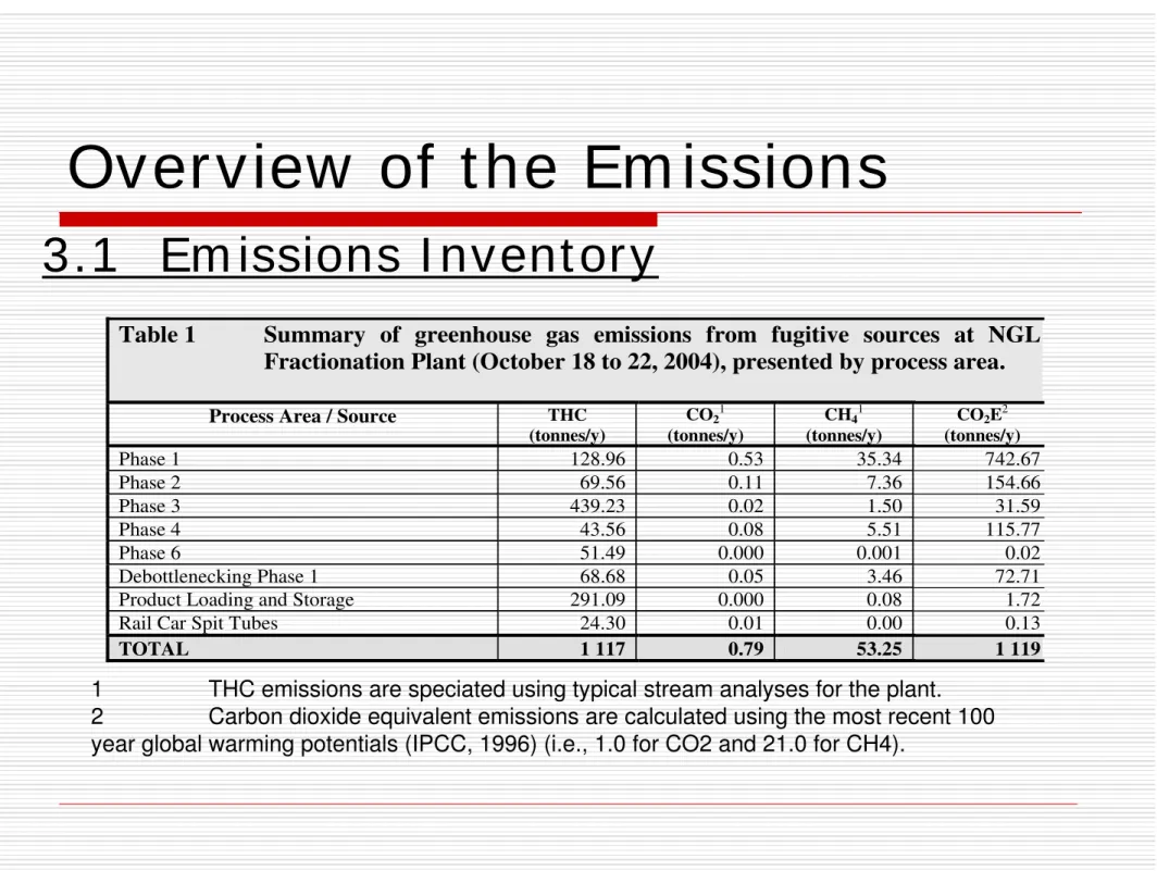
3.1 Em issions I nvent or y
Table 1 Summary of greenhouse gas emissions from fugitive sources at NGL Fractionation Plant (October 18 to 22, 2004), presented by process area.
Process Area / Source THC (tonnes/y)
CO21
(tonnes/y)
CH41
(tonnes/y)
CO2E2
(tonnes/y)
Phase 1 128.96 0.53 35.34 742.67 Phase 2 69.56 0.11 7.36 154.66 Phase 3 439.23 0.02 1.50 31.59 Phase 4 43.56 0.08 5.51 115.77 Phase 6 51.49 0.000 0.001 0.02 Debottlenecking Phase 1 68.68 0.05 3.46 72.71 Product Loading and Storage 291.09 0.000 0.08 1.72 Rail Car Spit Tubes 24.30 0.01 0.00 0.13
TOTAL 1 117 0.79 53.25 1 119
1 THC emissions are speciated using typical stream analyses for the plant.
Over view of t he Em issions
Phase 3 39.3% Phase 1
11.5% Phase 2 6.2% Spit Tubes
2.2% Product Storage and
Loading 26.1%
Debottleneck Phase 1 6.2%
Phase 6 4.6%
Phase 4 3.9%
Over view of t he Em issions
Debottleneck Phase 1 6.5%
Product Storage and Loading
0.2%
Spit Tubes 0.01%
Phase 2 13.8% Phase 6
0.002% Phase 4
10.3%
Phase 3 2.8%
Phase 1 66.4%
Over view of t he Em issions
3.2 Av er age Com ponent Em ission Rat es
Table 2 Fraction of leaking components and average component emission rates for data collected at Gas Fractionation Plant (October 18 to 22, 2004).
95 % Confidence Limits Component
Number of Components
Surveyed
Number of Leakers
Percentage of Components
Leaking
Average Emission Rate
(kg/h/source) Lower Upper
Connectors 68 670 107 0.14 0.000211 0.000092 0.000331 Block Valves 7 471 284 3.80 0.006452 0.00495 0.00796
Over view of t he Em issions
Open-Ended Lines 25.0%
Other
0.001% Pump Seals 10.2%
Control Valves 9.1%
Connectors 14.7%
Valves 37.7% Pressure Relief Valves
1.0%
Crank Case Vents 2.4%
Over view of t he Em issions
3.3 Sit e- Specific Em ission Fact or s
Table 3 Comparison of average emission factors derived from collected data to other published values (kg/h/source).
Source Fractionation
Plant1
CAPP2 Gas Facilities
U.S. EPA Gas Facilities3
U.S. EPA Refineries4
Connectors 2.11e-04 2.53e-03 3.048e-04 2.5e-04 Block Valves 6.45e-03 4.351e-02 3.400e-03 2.68e-02
Control Valves 1.67e-02 N/A N/A N/A Open-Ended Lines 5.55e-02 3.73e-03 9.015e-04 2.30e-03 Pressure Regulators 4.05e-05 N/A N/A N/A Pump Seals 1.22e-01 2.139e-01 N/A 1.14e-01 Crank Case Vents 5.18e-01 N/A N/A N/A Orifice Meters ND N/A N/A N/A Compressor Seals ND 8.049e-01 1.172e-00 6.36e-01 Pressure Relief Valves 4.79e-03 1.210e-01 2.238e-03 1.60e-01
N/A Average emission factor for this source type is not available. ND Leaks for this type of component not detected at the Gas Fractionation Facility.
1 Based on data collected at Gas Fractionation Plant October 18 to 22, 2004.
2 Source: Canadian Association of Petroleum Producers. 1999. A Detailed Inventory of CH4 and VOC Emissions from Upstream Oil and Gas Operations in Canada. Volume 2: Development of the Upstream Emissions Inventory. Calgary, AB.
3 Source: U.S. EPA and GRI. 1996. Methane Emissions from the Natural Gas Industry. Volume 8: Equipment Leaks. Research Triangle Park, NC 27711
Em ission Reduct ion Oppor t unit ies
4.1 Fugit ive Equipm ent Leaks
Tot al gas losses: 470.8 x 10
3m
3/ y
Value pr oduct lost : est . CAN $386,465 annually.
423 leaking com ponent s;
320 of t hese ar e est im at ed t o be econom ical t o
r epair .
I m plem ent ing all cost - effect ive equipm ent r epair s
ident ified w ould r esult in net pr esent savings of
CAN $1,055,850 and r educe hydr ocar bon losses by
465.0 x 10
3m
3/ y and GHG em issions by 826.5
Table 5
Summary of ten largest cost-effective emission reduction opportunities.
CEL Tag ID (Yellow)
LSI Tag ID (Blue and
Yellow)
Process Unit / Location Component Type
Emission Rate (103
m3/y)
Value of Gas ($/year) Payout Period (years)
Y133 CM-12.201/Splitter Compressor -
0.5" Gate valve seat Open-ended line - 4'' 111.920 115494 0.002 B22 PM-18.204/LPG Transfer Pump -
GREATER THAN 18.4% Gate valve - 4'' 13.246 12620 0.02 5305 HT-16.207AB/Depropanizer
Overhead Condenser - Gate valve - 6'' 13.697 10624 0.02 5641 Y200 PV-17.11/Butane Treater - union Threaded connection - 1'' 8.678 8955 0.003
B77 PM-18.15/Propane Loading Pump
- GREATER THAN 18.4% Pump seal - 6'' 22.397 17373 0.03 5213 B238 PM-18.209/Debutanizer Reflux
Pump - Gate valve - 8'' 2.672 3919 0.1 5637A B194A Next to PV-17.11 – union Threaded connection - 1'' 6.942 7164 0.004
B97 PM-18.702/Propane Loading
Pump Gate valve - 10'' 4.327 3356 0.1 5371
CM-12.02/Regen Gas Recycle Compressor - B11 (GREATER THAN 18.42%)
Valve cover - 1'' 30.293 6026 0.03 Y141 PM-18.401/EP to Pump –
FLAMEOUT Pump seal 12.471 12007 0.04
Leak Det ect ion Met hodology
Com par ison
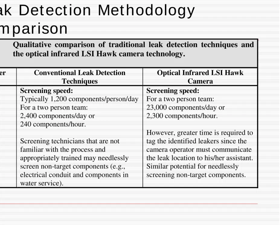
Table 6
Qualitative comparison of traditional leak detection techniques and
the optical infrared LSI Hawk camera technology.
Parameter Conventional Leak Detection Techniques
Optical Infrared LSI Hawk Camera
Speed Screening speed:
Typically 1,200 components/person/day For a two person team:
2,400 components/day or 240 components/hour.
Screening technicians that are not familiar with the process and
appropriately trained may needlessly screen non-target components (e.g., electrical conduit and components in water service).
Screening speed:
For a two person team: 23,000 components/day or 2,300 components/hour.
Siz e : Size and w eight have
im pr oved over t he Haw k ver sion.
D iff icu lt t o a cce ss com pon e n t s:
Usin g t h e ca m e r a e le v a t e d com pon e n t s a n d ot h e r
difficu lt a cce ss loca t ion s ca n be scr e e n e d f r om t h e gr ou n d or a t a dist a n ce .
Siz e : Gas det ect or s and spr ay bot t les
ar e sm all and light - w eight and allow t he oper at or t o be ver y m obile in all areas.
D iff icu lt t o a cce ss com pon e n t s:
Depending on com ponent , ladder s or ot her access point s m ust be found. Ext ension poles m ay be used t o scr een r oofline vent s and ot her elevat ed
sour ces.
M obilit y
Opt ica l I n fr a r e d LSI H a w k Ca m e r a
Con v e n t ion a l Le a k D e t e ct ion Te ch n iqu e s Pa r a m e t e r
Applica t ion of Le a k D e fin it ion :
The cam er a oper at or is able t o qualit at ively assess t he size of each leaker ( i.e., sm all, m edium , lar ge) , but t he t echnology
cur r ent ly does not apply an obj ect ive leak definit ion.
Le a k I sola t ion : Cam er a can
m or e clear ly ‘see’ a sour ce of leakage despit e t he close
pr oxim it y of ot her leaking and non- leaking com ponent s.
Un con v e n t ion a l Le a k e r s: The
cam er a is m or e apt t o pick up leaking equipm ent com ponent s in unconvent ional places since a w ide field of view is used.
M isse d Sou r ce s: Less sensit ive
t o but st ill dependent on t he level of car e and at t ent ion of t he scr eening t echnician.
Applica t ion of Le a k D e f in it ion :
An obj ect ive leak definit ion ( i.e., US EPA definit ion of 1 per cent hydr ocar bon concent r at ion in vicinit y of leaker ) can be applied using gas det ect or s.
Le a k I sola t ion : I t is som et im es
difficult t o ident ify a leaking com ponent w her e t her e ar e high backgr ound
r eadings due t o int er fer ence fr om ot her near by leaking sour ces and in
congest ed ar eas.
Un con v e n t ion a l Le a k e r s: Tr adit ional
t echniques focus in on expect ed
sour ces and locat ions ( e.g., seal vent s, m echanical connect ions, cover s, et c) . Leakage at ot her point s on a
com ponent or on piping ( e.g., due t o cor r osion and m echanical dam age) m ay not be ident ified.
M isse d Sou r ce s: The r eliabilit y of t he
m et hod is highly dependent on t he car e and at t ent ion used by t he scr eening t echnician.
Le a k
I de n t ifica
t ion
Opt ica l I n fr a r e d LSI H a w k Ca m e r a
Con v e n t ion a l Le a k D e t e ct ion Te ch n iqu e s Pa r a m e t e r
Opt ica l I n fr a r e d LSI H a w k Ca m e r a
Con v e n t ion a l Le a k D e t e ct ion Te ch n iqu e s Pa r a m e t e r
Ta ble 6 Com pa r ison of a dv a n t a ge s a n d disa dv a n t a ge s of t r a d it ion a l le a k de t e ct ion t e ch n iqu e s a n d t h e opt ica l in fr a r e d LSI H a w k ca m e r a t e ch n ology .
Cam er a use r equir es individuals w it h specific t r aining.
Flir GasFindI R has aut om at ic cont r ast cont r ol, easier t o use t han HAWK but st ill r equir es t r aining and exper ience.
Tr adit ional t echniques ar e r elat iv ely sim ple t o lear n and r equir e lim it ed exper t ise.
Dat a can hav e high degr ee of var iabilit y.
Pot e n t ia l Applica t ion for Rou t in e LD AR
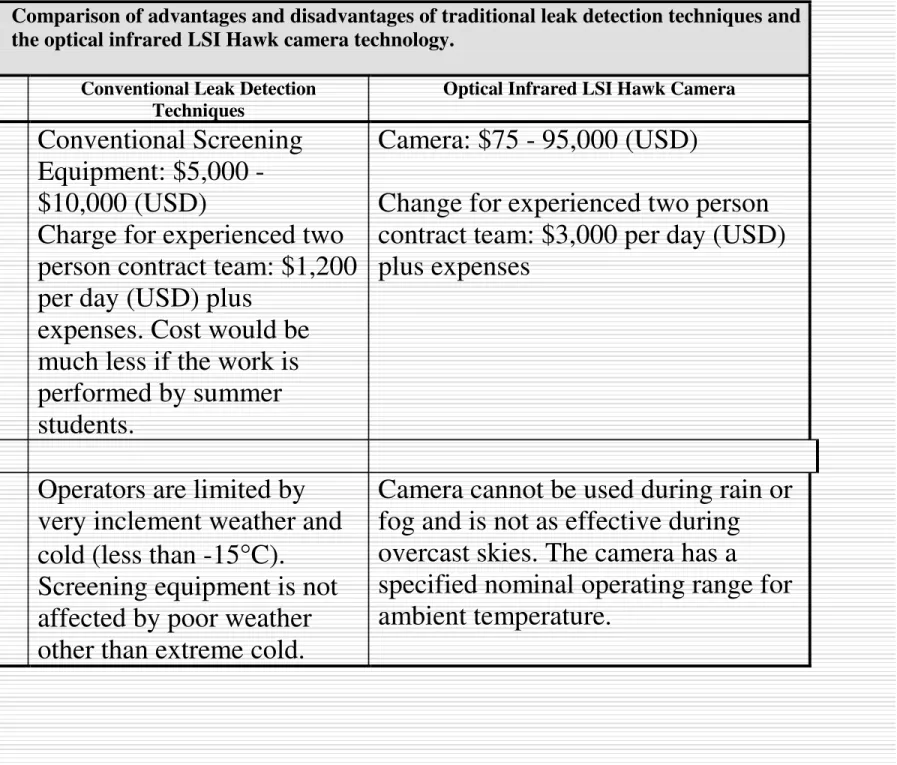
Table 6 Comparison of advantages and disadvantages of traditional leak detection techniques and the optical infrared LSI Hawk camera technology.
Parameter Conventional Leak Detection Techniques
Optical Infrared LSI Hawk Camera
Cost
Conventional Screening
Equipment: $5,000 -
$10,000 (USD)
Charge for experienced two
person contract team: $1,200
per day (USD) plus
expenses. Cost would be
much less if the work is
performed by summer
students.
Camera: $75 - 95,000 (USD)
Change for experienced two person
contract team: $3,000 per day (USD)
plus expenses
Weather
Operators are limited by
very inclement weather and
cold (less than -15
°
C).
Screening equipment is not
affected by poor weather
other than extreme cold.
Camera cannot be used during rain or
fog and is not as effective during
overcast skies. The camera has a
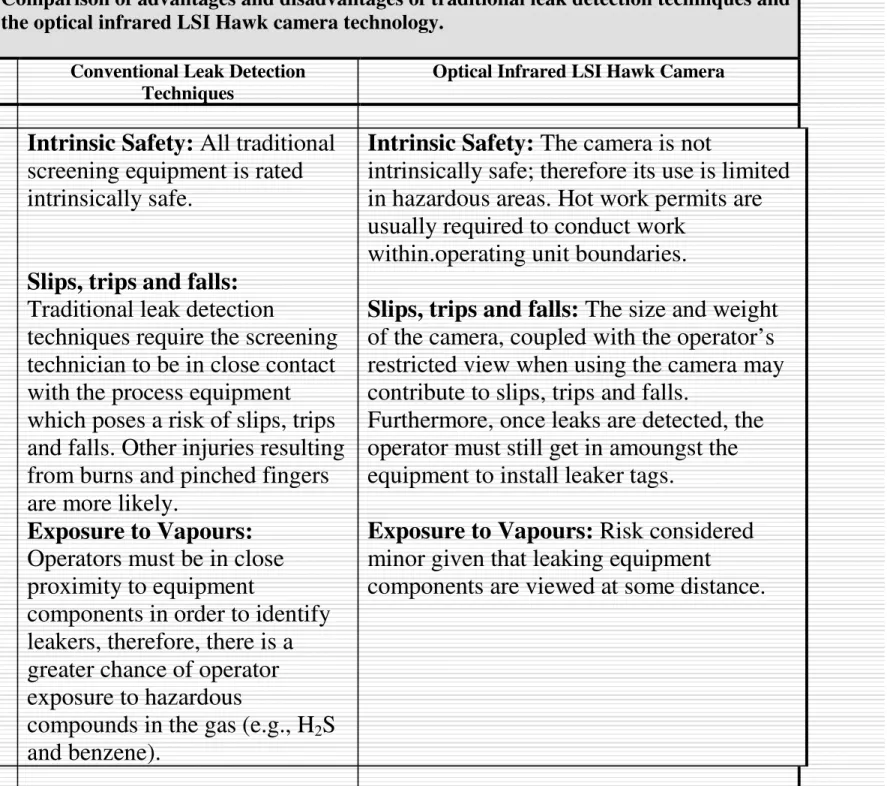
Table 6 Comparison of advantages and disadvantages of traditional leak detection techniques and the optical infrared LSI Hawk camera technology.
Parameter Conventional Leak Detection Techniques
Optical Infrared LSI Hawk Camera
Safety Intrinsic Safety: All traditional screening equipment is rated intrinsically safe.
Slips, trips and falls:
Traditional leak detection
techniques require the screening technician to be in close contact with the process equipment which poses a risk of slips, trips and falls. Other injuries resulting from burns and pinched fingers are more likely.
Exposure to Vapours:
Operators must be in close proximity to equipment
components in order to identify leakers, therefore, there is a greater chance of operator exposure to hazardous
compounds in the gas (e.g., H2S
and benzene).
Intrinsic Safety: The camera is not
intrinsically safe; therefore its use is limited in hazardous areas. Hot work permits are usually required to conduct work
within.operating unit boundaries.
Slips, trips and falls: The size and weight of the camera, coupled with the operator’s restricted view when using the camera may contribute to slips, trips and falls.
Furthermore, once leaks are detected, the operator must still get in amoungst the equipment to install leaker tags.
Exposure to Vapours: Risk considered minor given that leaking equipment