Classification of Sequential Circuits Based on τ
kNotation
Chia Yee Ooi and Hideo Fujiwara
Graduate School of Information Science, Nara Institute of Science and Technology Kansai Science City, 630-0192 Japan
E-mail: {chiaye-o, fujiwara}@is.naist.jp
Abstract
In this paper, we introduce a new test generation complexity notation called τk notation, which consists of τk-equivalent and τk-bounded, in order to clarify the classification of sequential circuits based on combinational test generation complexity. We reconsider the test generation complexity for the existing classes of acyclic sequential circuits. Several new classes of sequential circuits that cover some cyclic sequential circuits have been identified as being τ–equivalent and τ– bounded.
1. Introduction
It has been known for almost three decades that test generation problem is NP-complete. However, empirical observation shows that the combinational test generation problem seems to be O(nr) for some constant r, where n is the size of the circuit. Consequently, works have been done on searching for classes of sequential circuits with combinational test generation complexity.
Classes of sequential circuits with combinational test generation complexity include balanced sequential circuits [1], strongly balanced sequential circuits [2], internally balanced sequential circuits [4], switched balanced sequential circuits [5] and switched internally balanced sequential circuits [6]. In [3], a test generation model (TGM) transforms an acyclic sequential circuit into its combinational equivalent with logic duplicates at most d time frames where d is the sequential depth. On the other hand, the test generation problem for general sequential circuits, which is modeled by an iterative logic array, possesses greater time complexity than that of the acyclic sequential circuits does. To clarify the time complexity of the test generation, we introduce τk notation to classify the sequential circuits. In our discussion, τ(n) is used to denote the combinational test generation complexity where τ(n)=Θ(nr) for some constant r ≥ 2.
In Section 2, based on the asymptotic notation, we define a new test generation complexity notation that we call τk notation. In section 3, we reconsider the time
complexity of test generation problem for the existing classes of acyclic sequential circuits based on τk notation. In Section 4, several τ-equivalent and τ2–bounded classes of sequential circuits, which include some cyclic sequential circuits, are introduced. Conclusion is presented in the final section.
2. Preliminaries
Generally, asymptotic notation is used to describe the asymptotic running time of an algorithm. This notation is also convenient for describing the worst-case running time of the test generation problem. Let g(n) be a given function. The following describes briefly Θ(g(n)), O(g(n)) and Ω(g(n)). A function f(n) belongs to the set Θ(g(n)) if g(n) is an asymptotically tight bound for f(n). A function f(n) belongs to the set O(g(n)) if g(n) is an asymptotically upper bound for f(n) while a function f(n) belongs to the set Ω(g(n)) if g(n) is an asymptotically lower bound for f(n) [7].
To facilitate our discussion, we define the time complexity of test generation problem as follows.
PC: Combinational Test Generation Problem Instance: A combinational circuit C and a fault f. Question: Is there a test pattern to detect f in C? PS: Sequential Test Generation Problem Instance: A sequential circuit S and a fault f. Question: Is there a test sequence to detect f in S? Pα: Class α Test Generation Problem
Instance: A sequential circuit S in α and a fault f. Question: Is there a test sequence to detect f in S? Definition 1: The time complexity of a problem Pis the time complexity of the fastest algorithm for the problem P. Let TC(n), TS(n) and Tα(n) be the time complexity of PC, PS and Pα, respectively, where n is the size of the problem instance. TC(n), TS(n) and Tα(n) are also called test generation complexity for class C, class S and class α, respectively.
To show that TC(n) is the basics of the time complexity of the test generation problem, τ(n) is used to denote TC(n) in the following text, where τ(n)=O(nr) for some constant r ≥ 2.
IEEE 13th Asian Test Symposium (ATS'04), pp. 348-353, Nov. 2004.
Definition 2: T(n) is τk-equivalent if T(n)=Θ(τk(n)) and τk-bounded if T(n)=O(τk(n)), where k>0.
Definition 3: Class α is τk-equivalent if Tα(n)=Θ(τk(n)) and τk-bounded if Tα(n) = O(τk(n)), where k>0.
The following section reconsiders the test generation complexity of the existing classes of acyclic sequential circuits based on τk notation.
3. Existing classes of acyclic sequential circuits
A sequential circuit is said to be a balanced sequential circuit if, for any pair of primary input and primary output, all paths between them have the same number of flip-flops. A subclass of balanced sequential circuits, which is called strongly balanced sequential circuits, was then proposed. A sequential circuit is a strongly balanced sequential circuit if it is balanced and in addition, all paths between a node and all reachable PIs in its fan-in cone have the same number of flip-flops. A wider class of sequential circuits with combinational test generation complexity is internally balanced sequential circuits. A sequential circuit is an internally balanced sequential circuit if a circuit resulting from operation 1 of the extended combinational transformation in [4] on an acyclic sequential circuit is a balanced sequential circuit. It has been shown in the previous works that these three classes of sequential circuits can be converted into its combinational model. Thus, we have the following theorem based on τk notation.
Theorem 1: Internally balanced sequential circuits, balanced sequential circuits and strongly balanced sequential circuits are τ–equivalent.
An acyclic sequential circuit is a sequential circuit without feedback. Based on the test generation model called time expansion model or TEM in [10], we show that the test generation complexity for this class is not τ– equivalent.
Lemma 1: Let u and v be arbitrary logic blocks of an acyclic sequential circuit where u∈parents(v). The logic block u will be mapped to q different logic blocks in TEM if there are p different connections between logic block u and v with q different labels where p≥q.
Proof: Let v’ be the corresponding logic block of v in TEM and l(v’)=v and let ri(u,v) be labels for each connection (u,v) where 0≤i≤q. From the condition of input preservation and time consistency [10],
t(uj’)=t(v’)-ri(u,v) (1)
Since 0≤i≤q, the range of j is also 0≤j≤q. Since u=l(uj’), the lemma is proved.
Theorem 2: There exists an acyclic sequential circuit where its test generation complexity represented by TEM is not τ–equivalent.
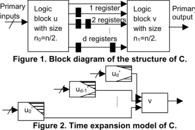
Proof:Let an acyclic sequential circuit, C has a structure represented by a topology graph G=(V,A,r) as follows:
1. V={u,v} where u∈parents(v) and A={ai | 0≤i≤d}; 2. ri(u,v)=i for 0≤i≤d where ri(u,v) represents a label on arc aj and d is the sequential depth of C.
Let n0 and n1 be the size of the logic block represented by vertices u and v, respectively where n0=n1=n/2 as shown in Figure 1. The primary inputs of C is denoted by a vector X and C has the following structure in the logic block u. For 0≤i≤d,
1. There is a fan-out point w in the logic block u from which output line zi of the logic block u is reachable for all i;
2. The sub-circuit ci with function zi*(X,w) has size ki, which is a constant, while the sub-circuit with function w(X) has size nw. The sub-circuit w(X) is non- overlapped to ci for all i. So,
=
≤
−
d
i i
w k
n n 2 0
(2) From Lemma 1, vertex u in the topology graph is mapped to (d+1) different vertices in TEM as shown in Figure 2. Let kij be the size of the logic portion with respect to an output zi of a logic block uj’. The size of the logic portion being removed nrj with kmax denotes maximum ki is as follows.
d k n
k k
n
rj
j i j i
ij rj
≤ •
≤
≤
≠
≠ max
max (3)
The size of the remaining logic portion of logic block uj’ is nj=n−nrj≥n−k •d
2 max
2 (4)
From equation (3) and (4), the size of the combinational equivalent of the acyclic sequential circuit represented in TEM is
) 2 (
) 2 (
) 2 (2
) 2 (2
2 max
0
max 0
1 0
d d n k
d
d n n k
n n n
n n N
d
j d
j
rj d
j j
+
− •
• +
=
+
− • + ≥
= − +
=
=
=
=
(5)
Therefore, the test generation complexity of the acyclic sequential circuit is
) (
)) ( (
))) 2 (
) 2 (( ( )
( max 2
r r A
n d
n d
d d n k
d N
T
Ω •
= Ω •
=
+
− •
• Ω +
=
=
τ τ τ
(6)
Since N ≤ d •n (7)
) (
)) ( (
r r A
n d O
n d O T
•
=
•
= τ
(8) )
( )
( r r r
A d n n
T =Θ • ≠Θ (9)
for some constant r.
for some constant r, for some constant r.
The equation (9) has proved the theorem.
However, there are other test generation models for acyclic sequential circuits besides TEM. “Is TA τ- equivalent?” is still an open question. No one has proved the answer is “Yes” but it might probably be “No” since the existing works show that generally in the time expansion model for the test generation problem, the logic duplication might happen for at most d time frames, where d is the sequential depth. Therefore, we have the following conjecture and theorem.
Figure 1. Block diagram of the structure of C.
Figure 2. Time expansion model of C. Conjecture 1: Acyclic sequential circuits is not τ- equivalent.
Theorem 3: Acyclic sequential circuits is τ2–bounded. Proof:See [9].
The practical observation shows that the test generation of acyclic sequential circuits is close to Θ(τ(n)) instead of Θ(τ2(n)) bound. Therefore, its test generation is still not very hard.
4. Classes of easily testable sequential circuits In this paper, we consider a class is easily testable if its test generation complexity is τ2-bounded. In other words, τ2-bounded classes and τ-equivalent classes are easily testable. Since a larger class means lower scan overhead is necessary in order to ensure the circuits in the class are easily testable, it is important to identify larger classes of easily testable kernels for the scanned design circuits. In this section, we introduce three classes of easily testable sequential circuits, which include some cyclic sequential circuits. These classes have less area overhead and at the same time, have similar test generation complexity compared to the acyclic sequential circuits.
Generally, the test generation problem of a cyclic sequential circuit is modeled by an iterative logic array that consists of several time frames so that it can be solved by combinational test generation techniques. The test generation problem involves the following three steps.
1. Derivation of the excitation state for a fault in the combinational part at time frame 0 by treating the present-state (PS) lines as primary inputs and the next- state (NS) lines as primary outputs;
2. State justification, which considers the fault effect in all time frames. This step extends the iterative array in backward direction for i time frames, where i is a positive integer;
3. State differentiation, which considers the fault effect in all time frames. This step extends the iterative array in forward direction for j time frames, where j is a positive integer.
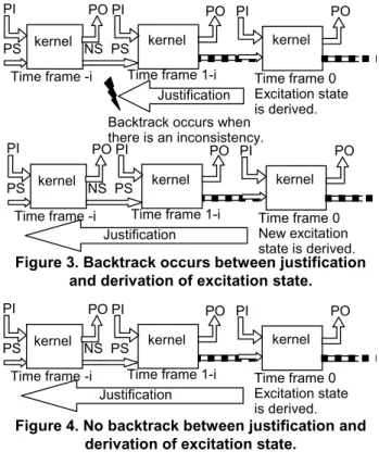
State differentiation that considers the fault effect in all time frames is also called fault propagation. Generally, backtracks might occur between the three steps. For a given fault, step 1 is performed to obtain an excitation state for state justification and fault propagation. If state justification or fault propagation fails, step 1 is performed again to get a different excitation state for justification and fault propagation as in Figure 3. Logic duplication of the circuit combinational part, which affects significantly the test generation complexity, takes place at every time frame except time frame 0. In the worst case, i and j are at most 2p, where p is the number of memory elements. Note that the state justifications that fail to justify an excitation state and the fault propagations that fail to propagate the fault effect to any primary output are also taken into account in determining the time complexity of the state justification TJ and the time complexity of the fault propagation TD respectively.
However, there are exceptional classes of sequential circuits with τ-equivalent or τ2-bounded test generation complexity, which include some cyclic sequential circuits. In such classes, backtrack between state justification, fault propagation and derivation of excitation state do not occur as illustrated in Figure 4. This means it is guaranteed that any excitation state can be justified and any activated fault can be propagated to a primary output. Since the derivation of the excitation state is done by the test generation on the combinational part at time frame 0, the time complexity TE(n) is always τ-equivalent. Therefore, if the state justification and fault propagation can be reduced to problem with τ2-bounded or τ-equivalent or less time complexity, the circuits become easily testable. The test generation complexity for a class of easily testable sequential circuits, TS(n) is
TS(n) ≤ TE(n)+ TJ+ TD
= τ(n)+ TJ+ TD (10)
The following sub-sections introduce three new classes of easily testable sequential circuits, which cover some cyclic sequential circuits.
v ud’
ud-1’
u0’ Logic block u with size n0=n/2.
Logic block v with size n1=n/2. Primary
inputs
Primary output
d registers 2 registers 1 register
Figure 3. Backtrack occurs between justification and derivation of excitation state.
Figure 4. No backtrack between justification and derivation of excitation state.
4.1. Length-bounded testable circuits
The number of time frames expanded by the state justification and fault propagation accounts for the length of a test sequence. In this section, we introduce a new class of easily testable sequential circuits called length- bounded testable circuits, the test sequence length of which can be bounded so that the class becomes easily testable.
Definition 4: A sequential circuit S is k-length-bounded testable with respect to a fault set F if the following conditions are satisfied.
1. For any state si, there exists a state justification sequence of length at most k;
2. For any pair of states (si, sif), there exists a fault propagation sequence of length at most k, where si is a fault-free state and sif is a faulty state corresponding to a fault f and f∈F.
Theorem 4: k-length-bounded testable circuits is τ2- bounded if k is O(n), where n is the size of the sequential circuits.
Proof: To generate a test sequence, firstly an excitation state is derived. Secondly, the excitation state is justified and thirdly, the fault effect is propagated to a primary output. Condition 1 of definition 4 implies that for any state si, there exists a state justification sequence and hence no backtrack occurs between the state justification
and derivation of excitation state. It also guarantees that the excitation state can be justified within sequence length of k. So, the state justification is performed on the combinational part duplication of size at most k•n. Generally, the time complexity of the state justification TJ
for an excitation state is τ–bounded. Therefore,
TJ(k•n) = O(τ(k•n)) (11)
Condition 2 of definition 4 implies that for any pair of states (si, sif), there exists a fault propagation sequence and hence no backtrack occurs between fault propagation, state justification and derivation of excitation. It also guarantees that the fault effect can be propagated to a primary output within sequence length of k. This means the fault propagation is performed on the combinational part duplication of size at most k•n. Generally, the time complexity of the fault propagation TD for an activated fault is τ–bounded. Therefore,
TD(k•n) = O(τ(k•n)) (12)
Let TLBT(n) be the test generation complexity for k- length-bounded testable circuits and k be O(n). Then,
TLBT(n) ≤ TE(n)+ TJ(k•n)+ TD(k•n)
= τ(n)+O(τ2(n))+ O(τ2(n))
= O(τ2(n)), which is τ2-bounded. (13) 4.2. Time-bounded testable circuits
In this section, another new class of sequential circuits called time-bounded testable circuits is introduced. Instead of being bounded by the test sequence length, the state justification and fault propagation for this class is bounded by the time complexity, which is a stronger condition. The time-bounded testable circuit is defined as follows.
Definition 5: A sequential circuit S is k-time-bounded testable with respect to a fault set F if the following conditions are satisfied.
1. For any state si, there exists a state justification sequence which can be obtained in time O(k);
2. For any pair of states (si, sif), there exists a fault propagation sequence which can be obtained in time O(k), where si is a fault-free state and sif is a faulty state corresponding to a fault f and f∈F.
Theorem 5: k-time-bounded testable circuits is τ- equivalent (τ2-bounded) if k is τ(n) (τ2(n)), where n is the size of the sequential circuits.
Proof: To generate a test sequence, firstly an excitation state is derived. Secondly, the excitation state is justified and thirdly, the fault effect is propagated to a primary output. From definition 5, it implies that for any state si
there exists a state justification sequence and for any pair of states (si, sif) there exists a fault propagation sequence. Hence, there is no backtrack between the derivation of excitation state, state justification and fault propagation.
PO PI PO
Time frame 0 Excitation state is derived. Backtrack occurs when
there is an inconsistency. Justification kernel
PI
PS
Time frame -i PO
NS PS PI
Time frame 1-i
kernel kernel
PO PI PO
Time frame 0 New excitation state is derived. Justification
kernel PI
PS
Time frame -i PO
NS PS PI
Time frame 1-i
kernel kernel
PO PI PO
Time frame 0 Excitation state is derived. Justification
kernel PI
PS
Time frame -i PO
NS PS PI
Time frame 1-i
kernel kernel
From condition 1, the excitation state can be justified in
time TJ = O(k) (14)
From condition 2, the fault effect can be propagated to a primary output in time TD = O(k) (15) The test generation complexity for k-time-bounded testable circuits, TTBT(n) is
TTBT(n) ≤ TE(n)+TJ+TD
= τ(n)+O(k)+O(k) (16)
= Θ(τ(n)) if k=τ(n) or O(τ2(n)) if k=τ2(n) Therefore, k-time-bounded testable circuits is τ– equivalent if k=τ(n) and τ2–bounded if k=τ2(n).
4.2.1. State-shiftable finite state machine realizations. It is hard to realize a time-bounded testable circuit in general. To show a concrete realization of time-bounded testable circuits, state-shiftable finite state machine is introduced here. A state-shiftable finite state machine [11] is a machine that possesses
1. transfer sequences of length at most [log2m] to carry the machine from state s0 to state si for all i, and 2. distinguishing sequences of length [log2m], which are arbitrary input sequences consisting of 2 input symbols, where m denotes the number of states. A sequential circuit that is realized from the state- shiftable finite state machine (FSM) is called state- shiftable finite state machine (FSM) realization.
Theorem 6: State-shiftable FSM realizations is τ- equivalent if the following conditions are satisfied.
1. The FSM contains a 2-column submachine equivalent to a binary shift register;
2. The output logic sub circuit OL’ with input symbols ε0 and ε1 is separate from other logic sub circuits; and
3. All the next state logic sub circuits with input symbols ε0 and ε1 are separate from each other, where input symbols ε0 and ε1 shift bit 0 and 1, respectively into the least significant bit or LSB of the next state. Proof: Refer [12].
4.3. Time-bounded validity-identifiable circuits The test generation of time-bounded validity- identifiable circuits is also bounded by the time complexity. However, different from the time-bounded testable circuits, the circuits has easily identifiable valid states and the state validity information, i.e. density of encoding is taken into account in the test generation. Density of encoding is defined as the fraction of the total number of possible states, which are valid [8].
Density of encoding=
states all of number
states valid of number
Definition 6: A sequential circuit S is k-time-bounded validity-identifiable with respect to a fault set F if the following conditions are satisfied.
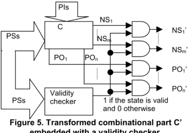
1. There exists a combinational circuit of size O(n) called validity checker (Figure 5) that can identify the validity of states, where n is the size of the sequential circuits;
2. For any valid state si, there exists a state justification sequence which can be obtained in time O(k);
3. For any pair of states (si, sif), there exists a fault propagation sequence which can be obtain in time O(k), where si is a fault-free valid state and sif is a faulty state corresponding to a fault f and f∈F.
Theorem 7: k-time-bounded validity-identifiable circuits is τ-equivalent (τ2-bounded) if k is τ(n) (τ2(n)), where n is the size of the sequential circuits.
Proof: To generate a test sequence for a given fault in a k- time-bounded validity-identifiable circuit, firstly a valid excitation state is derived at time frame 0. From condition 1, the excitation state is always guaranteed to be valid by embedding a validity checker in the combinational part of the sequential circuit as shown in Figure 5 such that a fault is testable in C with a valid state if and only if the fault is testable in the transformed combinational part C’. Secondly, the state justification is performed and lastly the fault propagation is performed. From definition 6, it is obvious that for any valid state si there exists a state justification sequence and for any pair of state (si,sif) there exists a fault propagation sequence. Hence, no backtrack occurs between the derivation of excitation state, state justification and fault propagation. Condition 2 guarantees that a state justification can be done in time
TJ = O(k) (17)
Condition 3 implies that the fault effect can be propagated to a primary output in time
TD = O(k) (18)
The test generation complexity for the k-time-bounded validity-identifiable circuits, TTBVI(n) is
TTBVI(n) ≤ TE(n)+TJ+TD
= τ(n)+O(k)+O(k) (19)
= Θ(τ(n)) if k=τ(n) or O(τ2(n)) if k=τ2(n) Therefore, k-time-bounded validity-identifiable circuits is τ–equivalent if k=τ(n) and τ2–bounded if k=τ2(n). 4.3.1. Counter-cycle one-hot design realizations. Counter-cycle one-hot design realization is presented to show how to realize the time-bounded validity-identifiable circuits concretely. Counter-cycle one-hot design realization satisfies the following conditions.
1. The number of codeword states is in O(n) and there exists a codeword checker of size O(n);
2. There exists an input symbol ε that strongly connects all codeword states accordingly in a counter- cycle such that
a. the output function λ(si,ε)=01 if the state transition function δ(si,ε)=s0; and
b. the output function λ(si,ε)=10 if the state transition function δ(si,ε)∈SV-{s0}; and
3. Output logic sub circuit OL’ with input symbol ε is separate from other logic sub circuits;
4. All the next state logic sub circuits with input symbol ε are separate from each other, and
5. The counter-cycle one-hot design realization is resettable, where si,s0∈SV, which is a set of all codeword states, s0 is the initial state of the counter- cycle and n is the size of the counter-cycle one-hot design realization.
Theorem 8: Counter-cycle one-hot design realizations is τ-equivalent.
Proof: Refer [12].
Figure 5. Transformed combinational part C’ embedded with a validity checker. 5. Conclusion
τk notation has been introduced in order to clarify the test generation complexity. Based on this notation, the test generation complexity for balanced sequential circuits, strongly balanced sequential circuits, internally balanced sequential circuits have been proved as being τ-equivalent while the test generation complexity for acyclic circuits has been showed as being τ2-bounded. We introduced three new classes of easily testable cyclic sequential circuits. The test generation complexity for k-length- bounded testable circuits is τ2-bounded if the parameter k is O(n) while the test generation complexity for k-time- bounded testable circuits and k-time-bounded validity- identifiable circuits is τ-equivalent (τ2-bounded) if the parameter k is τ(n) (τ2(n)), where n is the size of the sequential circuits. Our future works are to find an
effective DFT method and efficient test generation algorithm for each easily testable class.
Acknowledgments This work was supported in part by Japan Society for Promotion of Science (JSPS) under Grants-in-Aid for Scientific Research B(2) (No. 15300018). The authors would like to thank members of Fujiwara Laboratory who have given their valuable comments.
References
[1] R. Gupta and M. A. Breuer, “The BALLAST methodology for structured partial scan design,” IEEE Transactions on Computers, Vol. C-39, No. 4, pp. 538—544, April 1990. [2] A. Balakrishnan and S. T. Chakradhar, “Sequential
circuits with combinational test generation complexity,” Proc. IEEE International Conf. VLSI Design, pp. 111— 117, January 1996.
[3] R. Gupta and M. A. Breuer, “Testability properties of acyclic structures and applications to partial scan design,” Proc. IEEE VLSI Test Symp, pp. 49—54, 1992.
[4] H. Fujiwara, “ A new class of sequential circuits with combinational test generation complexity,” IEEE Transactions on Computers, Vol. 49, No. 9, pp. 895—905, September 2000.
[5] R. Gupta and M. A. Breuer, “Partial scan design of register transfer level circuits,” Journal of Electronic Testing: Theory and Applications, Vol. 7, pp. 25—46, 1995.
[6] M. Inoue, C. Jinno and H. Fujiwara, “An extended class of sequential circuits with combinational test generation complexity,” Proc. of 20th International Conference on Computer Design, pp. 200—205, September 16—18, 2002.
[7] T. H. Cormen, C. E. Leiserson and R. L. Rivest, Introduction of Algorithms, The MIT Press, 1990. [8] T. E. Marchok, A. El-Maleh, V. Maly and J. Rajski, “A
Complexity Analysis of Sequential ATPG,” IEEE Transactions on Computer-Aided-Design of Integrated Circuits and Systems, Vol. 15, No. 11, pp. 1409—1423, November 1996.
[9] C. Y. Ooi and H. Fujiwara, “Classification of sequential circuits based on combinational test generation complexity,” NAIST Information Science Technical Report, NAIST-IS-TR2004001, January 2004.
[10] T. Inoue, T. Hosokawa, T. Mihara and H. Fujiwara, “An optimal time expansion model based on combinational ATPG for RT level circuits,” IEEE the 7th Asian Test Symposium (ATS’98), pp. 190—197, December 1998. [11]. Hideo Fujiwara and Kozo Kinoshita, “Easily testable
sequential machines,” Technology Reports of The Osaka University, Vol. 24, No. 1214, 1974.
[12] C. Y. Ooi and H. Fujiwara, “Some τ-equivalent classes of sequential circuits,” NAIST Information Science Technical Report, NAIST-IS-TR2004002, June 2004. PSs
PIs
C
Validity checker
NS1’
NSm’
PO1’
POn’
PO1 POn
PSs 1 if the state is valid
and 0 otherwise NS1
NSm