A High-Level Synthesis Method for Weakly Testable Data Paths
Michiko Inoue† Takeshi Higashimura† Kenji Noda‡
Toshimitsu Masuzawa† and Hideo Fujiwara†
†Nara Institute of Sience and Technology
Ikoma, Nara, 630-0101 Japan
‡ULSI Systems Development Laboratories, NEC
Kawasaki, 211-0011 Japan
Abstract
We present a high-level synthesis method that considers weak testability of generated register-transfer level (RTL) data paths, as well as their area and performance. The weak testability, proposed in our previous work, is a testa- bility measure of RTL data paths for non-scan design. We introduce a design objective for weak testability that is a condition on resource sharing sufficient for weak testability. We propose a heuristic synthesis algorithm that generates a weakly testable data path while minimizing area under a performance constraint.
Key words: high-level synthesis, testability, sequential ATPG, non-scan design
1. Introduction
This paper addresses testability consideration of VLSI circuits during high-level synthesis. Such early considera- tion to testability in the design process is one of the most ef- fective ways to reduce testing cost. High-level synthesis for testability has been investigated in the several literatures[6]. They include such various testability goals as partial scan designs easily testable for sequential automatic test pattern generation (ATPG)[14, 8, 7, 11], full scan designs to make combinational ATPG[12] applicable, designs for hierarchi- cal testability[2], or designs for self testability[1, 5, 4]. In this paper, we propose a high-level synthesis method gener- ating easily testable data paths. Our work is mainly different from the previous related works in the following two points. (1) Our target is a weak testability which is a testability mea- sure of register-transfer level (RTL) data paths whose target
This work was supported in part by Semiconductor Technology Aca- demic Research Center (STARC) under the Research Project and in part by the Ministry of Education, Science, Sports and Culture, Japan under the Grant-in-Aid for Scientific Research B(2) (No.09480054).
is non-scan design for sequential ATPG[15]. (2) We give testability consideration from the beginning of high-level synthesis. High-level synthesis consists of several tasks such as scheduling and binding. In most works (except for a few) on high-level synthesis for testability, testability is considered only during binding after scheduling.
Scan design is the most popular method generating eas- ily testable design both for combinational and sequential ATPG. Full scan design guarantees high fault coverage and high fault efficiency obtained by combinational ATPG, but it makes much sacrifices of performance and area and it takes long test application time. Though partial scan de- sign improves such disadvantages while giving up combina- tional ATPG, there still remains problems of area overhead and long test application time. Moreover, scan design has another disadvantage, incapability of at-speed testing[9]. Recently, some non-scan design-for-testability (DFT) tech- niques for RTL data paths were proposed by Dey et al.[3] and Takabatake et al.[15]. The latter is our previous work, where we defined a new testability measure called weak testabilityfor RTL data paths and presented a DFT tech- nique which uses thru module to make the data path weakly testable. Experimental results showed the effectiveness of the proposed testability measure and the DFT technique. In this paper, we consider the weak testability during high- level synthesis that is a design stage earlier than RTL. This is the first high-level synthesis technique generating easily testable non-scan design for sequential ATPG.
Scheduling and binding are main tasks of high-level syn- thesis. Scheduling assigns operations to control steps where they are executed. Binding assigns variables and delays to registers, operations to operational modules, and data transfers to interconnection units (e.g., connection lines and multiplexors). Testability of an RTL data path much de- pends on the data path structure, and binding determines the structure. Therefore, many previous works consider testability during binding after scheduling. There are some
IEEE the 7th asian test symposium (ATS'98), pp. 40-45, Dec. 1998.
few works, to the best of our knowledge, that consider testability during scheduling[8, 5, 14, 4]. In the first two works[8, 5], scheduling methods are not their major contri- bution. They consider some supplementary heuristic rules to support the other tasks succeeding to the scheduling. In other works, generated RTL data paths are restricted to the model called a register file model[14] (They succeeded in simultaneous consideration of scheduling and operational module binding in this restricted model.), or a genetic algo- rithm approach that attempts to optimize area, performance and testability is proposed[4]. Scheduling has a great influ- ence on possibility of resource sharing and consequently on binding. Therefore, testability consideration from schedul- ing is necessary to generate testable design. In this pa- per, we propose a high-level synthesis method which gen- erates weakly testable data paths while optimizing perfor- mance and area. This method includes testability analysis for data flow graph (DFG) before synthesis, and high-level synthesis tasks, scheduling and binding, which consider the weak testability. The testability analysis phase is distinc- tive, where we extract constraints on resource sharing from a given DFG for testability. Testability is considered as con- straint on resource sharing in the succeeding high-level syn- thesis tasks such as scheduling and binding.
The rest of the paper is organized as follows. In Section 2, some basic definitions and a definition of weak testability are given. In Section 3, we propose a high-level synthesis method that generates weakly testable data path. Experi- mental results appear in Section 4. Conclusions are given in Section 5.
2. Models and Testability
Our high-level synthesis method is applied to a data flow graph (DFG), and transforms it into an RTL data path. We first define these two models at different levels.
A DFG is a digraph G V E , which represents behav- ior of a circuit. The nodes are classified into primary inputs, primary outputs, operations and delays. A delay is used in the case where an output sequence is computed iteratively for some input sequence, where a delay represents to hold a value obtained in one iteration to use in the succeeding iter- ations. A directed edge e u v in E represents a data flow from a node u to a node v. We call a set of edges outgoing from the same tail but not incoming to a delay a variable. Figure 1 shows a DFG of the 3rd order lattice wave filter (3LWF). It has one primary input PI, one primary output PO, 5 operations labeled by or , 3 delays D1 D2 D3, and 7 variables in out d1 d3 a b c.
A data path consists of hardware elements (primary in- puts, primary outputs, registers, multiplexors, and mod- ules)1and connection lines with some bit-width. We define
1We consider that constants are included within modules.
PI
D1 D2
* +
+ + +
D3
PO in
1
2
3 4
5 out a
b c d1
d3
Figure 1. DFG of 3LWF.
weak testability of a data path using weak controllability and weak observability of hardware elements. Intuitively, weak controllability of a hardware element H means that some value (not necessarily any) on the output of H can be justified from primary inputs, and weak observability of a hardware element H means that some value on the output of H can be propagated to primary outputs. In the following formal definition, H1 X(resp. H1 H2) means that there is a connection line from the output of a hardware element H1to an input X of some hardware element (resp. some in- put of a hardware element H2). Let
P I
,R
eg,M
uxandM
denote sets or primary inputs, registers, multiplexors, and modules, respectively. LetI N
Mdenote a set of inputs of a module M. For an input X of a module, let thru X denote a predicate representing that the module provides an oper- ation that returns just the value of the X . We call such an input thru input.Definition 1 weak controllability[15]
A set of weakly controllable hardware elements is the min- imum set
H
wcsatisfying the following conditions.1. A primary input. I
P I
IH
wc.2. A register or multiplexor with a weakly controllable input.
H
R
egM
ux HH
wcH H HH
wc.3. A module only with weakly controllable inputs or with a weakly controllable thru input.
M
M
XI N
M HH
wc H XX
I N
M thru X HH
wc H X MH
wc.Definition 2 weak observability[15]
A set of weakly observable hardware elements is the mini- mum set
H
wosatisfying the following conditions.1. A primary output. O
P O
OH
wo.2. A hardware element connecting to a weakly observ- able register or multiplexor.
H
R
egM
ux HH
wo H H HH
wo.3. A hardware element connecting to a weakly observ- able module where the connecting input is a thru input or all the other inputs are weakly controllable.
M
M
MH
wo XI N
MH X thru XX
I N
M X HH
wcH XH
H
wo.Definition 3 weak testability[15]
A data path DP is weakly testable iff all registers in DP are weakly controllable and weakly observable.
We assume that from any register there exists a path to some primary output. In this case, if all registers in a data path are weakly controllable, all registers are also weakly observable, and hence the data path is weakly testable. Therefore, we consider only weak controllability in the fol- lowing.
3. High-level synthesis for weak testability 3.1. Outline
We propose a high-level synthesis method for weak testability. This is a heuristic that generates a weakly testable data path with the minimum number of resources from a DFG under a time constraint, where a resource means a module or a register, and a time constraint is given as the number of control steps in which all operations must be executed. For simplicity, we assume disjoint operation type sets, that is, for each operation type, a corresponding module type is uniquely determined. Moreover, we assume that all operations are single-cycle operations.
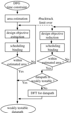
Weak testability has a good property that, before synthe- sis, we can consider a condition on resource sharing suffi- cient for weak testability of a synthesized data path. We call such a sufficient condition design objective for weak testa- bility, or just design objective. Figure 2 shows the outline of this method. In the method, we first estimate the num- ber of resources using force-directed scheduling[13] that is a heuristic minimizing the number of resources under a time constraint. Then we iteratively attempt design objective ex- traction, scheduling and binding until satisfying the estima- tion of the number of resource. In design objective extrac- tion, we analyze a DFG and extract a design objective as constraint on resource sharing for weak testability. If we cannot obtain a data path within the predetermined iteration limit, we reduce the extracted design objectives, and itera- tively attempt design objective reduction, scheduling, and binding until satisfying the resource estimation. Finally, we apply the DFT technique([15]) to a synthesized data path if it is not weakly testable.
DFG time constraint
weakly testable datapath design objective
extraction
scheduling binding
datapath is weakly testable ?
No
DFT for datapath area estimation
within estimated area ?
design objective reduction
scheduling binding
within estimated area ? No
No Yes
Yes Yes
#backtrack limit over
Figure 2. High-level synthesis method.
3.2. Design objective
We define weak controllability of an element in a par- tially bound DFG like for a data path. A partially bound DFG means that binding to resources are partially deter- mined. For a partially bound DFG, we call the informa- tion to specify which elements share a hardware element a sharing information. A sharing information is a set
B
B1 B2 Bk of sharing sets, where each sharing set Bi
represents a set of elements which share the same resource. For such a partially bound DFG, if some DFG element e is weakly controllable and it shares the same resource with another DFG element e , we consider e is also weakly con- trollable. We define weak controllability and weak testabil- ity on a DFG as follows. For a DFG, let
P I
d denote a set of primary inputs.Definition 4 weak controllability on a DFG
For a DFG G V E and a sharing information
B
, a set of weakly controllable elements in G is the minimum setE
wcsatisfying the followings. 1. A primary input.
pi
P I
d piE
wc.2. An edge outgoing from a weakly controllable node. u v E u
E
wc u vE
wc.3. A node whose all incoming edges are weakly control- lable.
v V u u u v E u v
E
wc vE
wc.4. An edge or node which shares a hardware element with some weakly controllable one.
B
B
x B x Ewc BE
wc. Definition 5 weak testability on a DFGFor a DFG G V E and a sharing information
B
, if all variables and delays in G are weakly controllable, G is weakly testable forB
.If some DFG element is weakly controllable for a shar- ing information
B
, the resource to which it is bound is also weakly controllable if the synthesized data path satisfiesB
. This implies that if a DFG G is weakly testable for a sharing informationB
,B
is a sufficient condition for weak testabil- ity of a data path synthesized from G. A design objective is a sharing information sufficient for weak testability. 3.3. Design objective extractionIn general, for a given DFG and a time constraint, there may be one or more design objectives. To extract good de- sign objectives, we introduce overlap degree of a sharing in- formation which represents difficulty for a sharing informa- tion to be satisfied. For two elements to share the same re- source, it is necessary that these two elements do not use the same control step. We derive overlap possibility ol p e1 e2
of two operations or two variables from ASAP and ALAP scheduling. The overlap possibility ol p e1 e2 0 implies that they never use the same control steps, therefore, they can share a resource. The value' implies that they nec- essarily use the same control step and they cannot share a resource. The value 1 implies they may use the same con- trol step. We define an overlap degree old of a sharing set Band of a sharing information
B
as follows.old B
-
e1e2 B e1 e2
ol p e1 e2
old
B -
B B old B
The value 0 of the overlap degree means that all elements in each sharing set are sure to use distinct control steps, while the value' means some elements in some sharing set use the same control step and they cannot share a resource.
We extract a design objective with a small overlap degree from a DFG by the following greedy method. Starting from an empty sharing information, we repeatedly augment it un- til it becomes a design objective. We consider two types of augmentation of a sharing information
B
. One is to add an element e to some sharing set B, where e is not weakly con- trollable forB
and all elements in B and e are assigned tothe same type of resource. Another is to add a new sharing set consisting of a weakly controllable element e1and a not weakly controllable element e2to
B
, where e1and e2are assigned to the same type of resource. In each iteration, we select the next augmentation as follows.1. Select the augmentation such that the increased over- lap degree is the smallest. If there are two or more such augmentations, consider the next.
2. Select the augmentation such that the increased num- ber of types of weakly controllable resources is the largest. If there are two or more such augmentations, consider the next.
3. Select the augmentation such that the increased num- ber of weakly controllable elements is the largest. If there are two or more such augmentations, select one of them, arbitrarily.
An extracted design objective is considered as constraint in the succeeding high-level synthesis tasks. If the succeed- ing tasks fail to satisfy the extracted design objective, we extract the next design objective. In this case, the last aug- mentation is canceled and the design objective extraction algorithm backtracks.
3.4. Scheduling
Scheduling assigns operations to control steps where they are executed. First we delete all delay nodes from a DFG, and apply a scheduling algorithm to the remained acyclic DFG. We schedule operations for a given sharing information to be satisfied. For two elements in the same sharing set to share a resource, it is necessary that two ele- ments are assigned to different control steps. To represent such a condition, we add new types of edges to a DFG. We define two types of edges an operation constraint edge and a variable constraint edge.
An operation constraint edge op1 op2 means that op2
must be executed after op1. Therefore, two operations never be executed at the same control step and they can share the same module. For two operations in the same sharing set with overlap possibility of 1, we add an operation constraint edge that is outgoing from the operation whose largest dis- tance from a primary output is not smaller and incoming to the other operation. A variable constraint edge op1 op2
means that op2must be executed at the same control step as op1or after. If there exist variable constraint edges from all operations that use a variable v1to an operation that gener- ates a variable v2, two variables never use the same control steps and they can share a register. For two variables in the same sharing set with overlap possibility of 1, we add variable constraint edges that are outgoing from all opera- tions which use the variable whose largest distance from a
primary output is not smaller and incoming to an operation which generates the other variable.
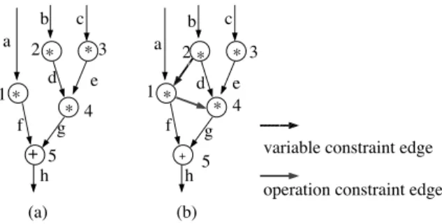
Example. Figure 3 shows an original DFG and an extended DFG for a design objective 1 4 b f where 1 and 4 are operations and b and f are variables. We add an op- eration constraint edge 1 4 for a sharing set 1 4 and a variable constraint edge 2 1 for a sharing set b f .
a
b c
d e
f g
h +
*
*
*
*
a
b c
d e
f g
h
+
*
*
*
*
variable constraint edge operation constraint edge
(a) (b)
1
2 3
4 5
1
2 3
4
5
Figure 3. (a) original DFG. (b) extended DFG.
We schedule the above extended DFG by the modified algorithm of the force-directed scheduling algorithm[13]. We modified it so as to consider operation constraint edges and variable constraint edges.
3.5. Binding
We consider design objective during register binding and the succeeding module binding. Register binding and mod- ule binding are performed on a register compatibility graph and a module compatibility graph, respectively. These are graphs that represent which DFG elements can share a re- source. In register binding, we first merge variables in the same sharing set into one node, and then apply a known minimum clique partition algorithm[16] to the merged com- patibility graph. Module binding performs similarly. We first merge operations in the same sharing set into one node. Then we repeatedly pick a maximal clique from the merged compatibility graph and assign operations in the clique to one module. We repeat this until all operations are assigned. To minimize the interconnection cost, we select a maximal clique so that operations that have common input registers or common output registers belong to the same clique. Fi- nally, we connect resources by connection lines and multi- plexors according to a DFG.
3.6. Design objective reduction
If we cannot obtain a weakly testable data path within the iteration limit, we reduce design objectives. Design objectives obtained in the preceding extraction are reduced to sharing information that may not be sufficient for weak
testability. We apply the following one element deletion and synthesis considering the reduced sharing information to the extracted design objectives in turn until we obtain a data path within the estimated number of resources. If we cannot obtain such a data path, we delete one more element from reduced sharing informations, and repeat this.
We explain how to delete one element from some sharing set in a design objective or a sharing information
B
. Let Gebe an extended DFG for
B
. We first find constraint edges that cause the dissatisfaction ofB
. For this purpose, we ap- ply the modified algorithm of a well known list scheduling algorithm[10] to Ge. It is a heuristic scheduling algorithm that minimizes the number of control steps under a resource number constraint. We modified it so as to consider con- straint edges. If scheduling result exceeds the time con- straint and some constraint edges appear on critical paths, we select an element to be deleted among the operations and variables corresponding to such constraint edges. Other- wise we select an element among all elements inB
. Among these candidates, we select the element such that an overlap degree is decreased most by its deletion.4. Experimental result
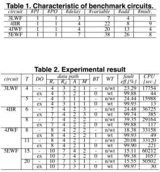
We made experiments on the proposed high-level test synthesis method. Experiments were made on four bench- mark circuits, the 3rd order lattice wave filter (3LWF, Fig.1), the 4th order IIR cascade filter (4IIR), the 4th order Jaumann wave filter (4JWF) and the 5th order digital ellip- tical filter (5EWF), under different time constraints. Table 1 shows the characteristic of these benchmark circuits. We applied our synthesis method to these and generated weakly testable data paths (Table 2). A column T denotes time con- straints. In a column DO, ’–’ means the synthesis without design objective extraction and “ex” means the synthesis considering extracted design objectives. Columns Rv, Rd, Aand M denote the numbers of registers for variables, reg- isters for delays, adders and multipliers of the synthesized RTL data path, respectively, and BT denote the number of backtracks of design objective extraction caused by the dis- satisfaction of the succeeding synthesis. In a column WT,
“wt” means that an obtained data path is weakly testable and “n/wt” means a data path is not weakly testable. We then applied test generation to show the effectiveness of weak testability. We used a logic synthesis tool AutoLogicII (Mentor Graphics Co.) and an ATPG tool TestGen (Sunrise Test System, Inc.) on a Sun Ultra (300MHz 2). Columns fault eff. and CPU denote the fault efficiency and the test generation time.
For all benchmark circuits and all time constraints, we obtained weakly testable data paths with the same number of resources as the case without design objective extraction. In the case without design objective extraction, we did not
Table 1. Characteristic of benchmark circuits.
circuit #PI #PO #delay #variable #add #mult.
3LWF 1 1 3 7 4 1
4IIR 1 1 4 22 8 9
4JWF 1 1 4 20 13 4
5EWF 1 1 7 38 26 8
Table 2. Experimental result
data path fault CPU
circuit T DO R
v Rd A M BT WT eff.[%] [sec.]
3LWF 4 - 4 3 2 1 - n/wt 23.29 17754
ex 4 3 2 1 0 wt 99.88 44
5 - 4 3 1 1 - n/wt 24.44 15988
ex 4 3 1 1 0 wt 99.93 13
4IIR 6 - 7 4 2 3 - n/wt 24.48 36725
ex 7 4 2 3 0 wt 99.74 385
8 - 7 4 2 2 - n/wt 39.35 29164
ex 7 4 2 2 0 wt 99.88 117
4JWF 8 - 8 4 2 2 - n/wt 18.38 33158
ex 8 4 2 2 1 wt 99.93 49
11 - 8 4 2 1 - n/wt 20.08 33120
ex 8 4 2 1 0 wt 99.90 221
5EWF 15 - 10 7 4 2 - n/wt 15.11 60212
ex 10 7 4 2 0 wt 99.38 1057
20 - 10 7 3 1 - n/wt 15.55 50502
ex 10 7 3 1 0 wt 99.97 30
obtain any weakly testable data path. That is, our method realized weak testability without sacrifice of the number on resources. Moreover, in most cases (except for one case), the synthesis algorithm generated a data path for the design objective extracted first. This implies the effectiveness of the overlap degree. In the test generation result, weakly testable data paths have almost complete fault efficiency with small test generation time, while not weakly testable data paths have low fault efficiency.
5. Conclusions
In this paper, we proposed a high-level synthesis method that generates a weakly testable data path. We introduce a design objective for weak testability that is a condition on resource sharing sufficient for weak testability. We propose a high-level synthesis method using design objective ex- traction while minimizing the number of resources under a time constraint. We showed the effectiveness of the method by experiments on several benchmark circuits. In the ex- periments, we obtained weakly testable data paths with the same number of resources as the case without design objec- tive extraction. That is, we achieved weak testability with- out sacrifice of the number of resources. One of the future works is to evaluate the proposed method for more large scale circuits.
References
[1] L. Avra. Allocation and assinment in high-level synthesis for self-testable data path. In Proc. Intl. Test Conf., pages 463–472, 1991.
[2] S. Bhatia and N. Jha. Genesis: A behavioral synthesis sys- tem for hierachical testability. In Proc. European Design and Test Conf., pages 272–276, 1994.
[3] S. Dey and M. Potkonjak. Transforming behavioral speci- fications to facilitate synthesis of testable designs. In Proc. Intl. Test Conf., pages 184–193, 1994.
[4] M. K. Dhodhi, I. Ahmad, and A. A. Ismaeel. Data path synthesis for easy test testability. In Proc. Asian Test Symp., pages 317–322, 1994.
[5] I. G. Harris and A. Orailo˘glu. SYNCBIST: synthesis for concurrent built-in self-testability. In Proc. Intl. Conf. on Computer Design, pages 101–104, 1994.
[6] T.-C. Lee. High-Level Test Synthesis of Digital VLSI Circuit. Artech House Publishers, 1997.
[7] T.-C. Lee, N. Jha, and W. Wolf. Behavioral synthesis of highly testable data paths under non-scan and partial scan environments. In Proc. Design Automation Conf., 1993. [8] T.-C. Lee, W. Wolf, and N. Jha. Behavioral synthesis for
easy testability in data path scheduling. In Proc. Intl. Conf. on Computer Design, pages 616–619, 1992.
[9] P. Maxwell, R. C. Aitken, V. Johansen, and I. Chiang. The effect of different test sets on quality level prediction: When is 80% better than 90%? In Proc. the Intl. Test Conf., pages 358–364, 1991.
[10] M. C. McFarland, A. C. Parker, and R. Camposano. Tutorial on high-level synthesis. In Proc. 23th Design Automation Conf., pages 330–336, 1988.
[11] A. Mujumdar, R. Jain, and K. Saluja. Incorporationg per- formance and testability constraints during binding in high- level synthesis. IEEE Trans. on Computer-Aided-Design, 15(10):1212–1225, Oct. 1996.
[12] R. B. Norwood and E. J. McClusky. High-level synthesis for orthogonal scan. In Proc. VLSI Test Symp., pages 370–375, 1997.
[13] P. Paulin and J. Knight. Force-directed scheduling for the behavioral synthesis of ASIC’s. IEEE Transactions on Computer-Aided-Design, 8(6):661–679, 1989.
[14] M. Potkonjak, S. Dey, and R. Roy. Considering testabil- ity at behavioral level: Use of transformation for partial scan cost minimization under timing and area constraints. IEEE Trans. on Computer-Aided-Design, 14(5):531–546, May 1995.
[15] K. Takabatake, M. Inoue, T. Masuzawa, and H. Fujiwara. Non-scan design for testable data paths using thru operation. In Proc. Asia and South Pacific Design Automation Conf., pages 313–318, 1997.
[16] C. Tseng and D. P. Siewiorek. Automated synthesis of data paths in digital systems. IEEE trans. on CAD, 5(3), 1986.