Study of the unified control system of the magnets
in the KEKB/PF-AR accelerators
Tatsuro Nakamura
DOCTOR OF PHILOSOPHY
Department of Accelerator Science
School of High Energy Accelerator Science
The Graduate University for Advanced Studies
2011
Abstract
KEKB is a double-ring, asymmetric-energy, electron-positron collider, which is pursuing luminosity frontier. In order to improve its luminosity, commissioning has been continued incessantly. Because various machine tunings are frequently necessary during the commissioning, the control system is required to be highly responsive and flexible. Especially for the magnets and magnet power supplies, which define optics of the accelerators, the efficiency and flexibility of the control system are essentially important.
To achieve these requirements the design and the construction of the control system of the magnet power supplies have been carried out with the following view points. The most important point is the unified treatment of the magnet power supplies. KEKB has wide variety of the magnet power supplies, from the large power supplies for the main bending magnets to the small power supplies for the steering magnets. The bending magnets, quadrupole magnets, sextupole magnets and steering magnets require different type of power supplies and are operated in the different manner. The magnet can be iron core or air core, superconducting or normal conducting, with or without auxiliary windings, and so on. There are many different types of the magnet power supplies, in the scale, in the regulation scheme, bipolar or unipolar, with or without pole changer, and so on. Although such differences exist, focusing on the common properties of the magnet power supplies, the hardware of the interface and the software of the control system have been designed not separately for each type but designed as universal for the all types as possible.
Another important point is reliability. Although resources of the budget and the man power to construct KEKB have been limited, it has been required to keep the control system reliable. Not only in the construction phase but also in the maintenance phase, reliability should be considered. In order to maintain reliability in such conditions, the design strategy adapted is simplification. Especially it is important how to simplify the interface to the magnet power supply with the control computer. It greatly influences the reliability of the control system. In the previous, TRISTAN, control system CAMAC was adopted as the standard interface. Between the CAMAC module and the magnet power supply there were wired signal lines for each signal one by one. If KEKB adopted the same scheme, the amount of wires could be huge because the number of magnet power supplies in KEKB is large, more than double. In KEKB, instead of the parallel wiring, one serial line has been introduced for a magnet power supply. All signals are exchanged through the single serial line.
Thus, considering unification and simplification as the important principles, the magnet power supply control system has been developed. There are two major tasks in the development. One is the development of the interface between the control computers and the magnet power supplies. The other is the development of the control software. KEKB control system has adopted EPICS (Experimental Physics and Industrial Control System) as the core software framework. And two types of computers have been installed. One is IOC (Input/Output Controller), which directly controls the equipments through its own hardware connection to the equipments. The other is OPI (Operator Interface), which runs various high level applications like operator interface.
The synchronous operation of multiple magnet power supplies is required in order to change optics without loosing stored beams. For this purpose, the synchronous setting has been designed that the tracking data are calculated in the IOC and sent to the magnet power supply beforehand and then the synchronous start signal triggers the synchronous tacking. In this method the magnet power supply is required to store the array data for the tracking and to set them in sequence with the interval clock. Although it requires some intelligence in the magnet power supply, total system can be simplified and flexible operation is possible. ARCNET (Attached Resource Computer NETwork) has been adopted as the serial interface. It supports relatively long packet and communication speed is enough for our purpose. The twisted-pair cable with RS485 type differential driver has been chosen as the media of ARCNET. This configuration allows multi-drop wiring. The synchronous start signal is also delivered by the cable combined with ARCNET. Thus, the simplification of the wirings has been achieved. For the implementation of the ARCNET interface, the PSICM (Power Supply Interface Controller Module) has been developed. It is the plug-in module in the magnet power supply and has an ARCNET interface and a microcomputer with the control software (firmware). PSICM has been designed to be universal for any type of the power supplies. All of the magnet power supplies can be controlled in single manner using PSICM.
In the development of the control software, the magnet power supplies have been treated in unified manner. Among the different types of the magnets and the power supplies, the common features are abstracted. Major functions incorporated in the IOC are followings.
(1) parameter conversion from abstracted magnetic field strength to the current (2) regular setting sequences to reduce the magnetic hysteresis problem
(3) synchronous and asynchronous operations for the current setting
Although the magnet power supply control system has been originally designed for the KEKB, because of its universal design, it has been also well applied to the PF-AR
magnet control system. PF-AR has been upgraded in 2001. At that time its control system has been renewed using the same way as KEKB. PSICM can be used for PF-AR without any modifications. Most of the control software for KEKB can be also applied for PF-AR. In addition for PF-AR, the pattern operation of the acceleration has been developed based on the same mechanism of the synchronous operation. The tracking pattern of the acceleration can be flexibly configured.
As the unification has been implemented in the IOC layer, the magnet power supply can be treated as the abstracted object independent of the hardware in the OPI layer. Such abstraction has reduced the load of the development of the user application programs. Thus, during a decade of the commissioning of the KEKB accelerators, many application programs have been developed and have contributed to the tuning up and improvement of the accelerators continuously.
Contents
1. Introduction... 8
1-1. Motivation and approach of the study ... 8
1-2. Composition of the thesis... 9
2. KEKB magnet power supplies and control system... 11
2-1. The magnets and the magnet power supplies for the KEKB accelerators ... 11
2-2. EPICS ... 12
2-2-1. IOC database... 14
2-2-2. Channel Access... 14
2-3. KEKB accelerator control system... 15
2-3-1. IOC in KEKB ... 16
2-3-2. Control network ... 18
2-3-3. OPI layer ... 18
3. Development of the interface to the magnet power supply ... 20
3-1. Prerequisites of the design of the interface ... 20
3-2. Consideration of the CAMAC system of TRISTAN ... 20
3-3. Serial communication for the interface... 21
3-4. Synchronous operation of the multiple magnet power supplies ... 22
3-4-1. The required specifications of the synchronous setting ... 22
3-4-2. Implementation of the synchronous setting ... 24
3-5. Delivery system of the synchronous start signal... 26
3-5-1. Event timing system ... 26
3-5-2. Delivery of the synchronous start signal from the IOC to the magnet power supply... 27
3-6. PSICM ... 28
3-7. ARCNET interface VME module for the magnet power supply... 30
3-8. ARCNET hub for the magnet power supply ... 32
3-9. Entire configuration of the magnet power supply control system ... 33
3-9-1. Current monitor system of the magnet power supply... 34
3-9-2. Interlock signal from the magnet... 35
4. Development of the control software... 36
4-1. 3-layers scheme of the distributed control system ... 36
4-1-1. Software of the PSICM layer... 36
4-1-2. Software of the IOC layer ... 37
4-1-3. Software of the OPI layer ... 39
4-2. Required functions for the magnet power supply control software ... 39
4-3. Control parameter... 40
4-3-1. Magnetic field as the control parameter ... 40
4-3-2. Excitation function... 41
4-3-3. Virtual parameter and QCS virtual magnet power supplies ... 43
4-4. Standardization... 44
4-4-1. Direct setting... 44
4-4-2. Sequence setting ... 45
4-4-3. Standardize setting... 45
4-4-4. Simple standardize setting... 46
4-5. Asynchronous setting and Synchronous setting ... 47
4-5-1. Asynchronous setting... 47
4-5-2. Synchronous setting... 47
4-5-2-1. Synchronous setting server ... 47
4-5-2-2. Synchronous pole change server ... 50
4-6. Exclusion control for the magnet with auxiliary coils... 52
4-7. Implementation of the software on the IOC ... 54
5. User application programs for the operation... 57
5-1. Operation panel for the storage rings ... 57
5-2. Operation panel for the injection BT lines... 59
5-3. Injection mode switching panel for the BT line ... 60
5-4. Optics panel for the storage rings ... 61
5-5. Orbit correction panel for the storage rings... 62
6. PF-AR magnet power supply control system ... 64
6-1. Upgrade of PF-AR ... 64
6-2. Treatment of the existing magnet power supplies of PF-AR ... 65
6-3. Tracking of the acceleration of PF-AR ... 65
6-4. Control system of the injection BT line of PF-AR... 67
7. Discussion... 68
7-1. Simplification ... 68
7-2. Unification... 68
7-3. Prerequisite and limit of application of the methodology ... 69
7-4. Balance between hardware and software ... 70
8. Summary ... 72
Acknowledgements... 75
References... 77
1. Introduction
1-1. Motivation and approach of the study
KEK B-factory (KEKB) is an asymmetric-energy electron-positron collider. It consists of two storage rings. One is LER (Low Energy Ring), which stores the 3.5GeV/c positron beam, and the other is HER (High Energy Ring), which stores 8GeV/c electron beam. Both beams collide at the Interaction Point (IP) to produce intensive pairs of B meson and anti-B meson. Belle detector is installed at the IP. The B mesons are provided for the various experiments of the elementary particle physics, especially for the experimental studies of the CP violation in B meson decays.
These experiments require large amount of B mesons in order to improve statistical precision. Thus, KEKB has challenged to the aggressive goal that the design luminosity is 1034cm-2s-1, which is one-order of magnitude higher luminosity than ever achieved before. To achieve such high luminosity the commissioning phase of KEKB was expected to be continued for a long time. Indeed the commissioning has been continued during the whole operation period. The operation of KEKB started in 1998. The design luminosity has been achieved in 2003. Even after that the effort to improve the luminosity has been still continued. Finally the luminosity has reached to the twice of the design value in 2009.
Because various machine tunings are frequently necessary during the commissioning, the control system is required to be highly responsive and flexible. Especially for the magnets and magnet power supplies, which define optics of the accelerators, the efficiency and flexibility of the control system are essentially important. The main theme of this thesis is a methodology to design and to construct a control system of the magnet power supplies to achieve these requirements.
In the KEKB, the design and the construction of the control system of the magnet power supplies have been carried out with the following view points. The most important point is the unified treatment of the magnet power supplies. KEKB has wide variety of the magnet power supplies, from the large power supplies for the main bending magnets to the small power supplies for the steering magnets. The bending magnets, quadrupole magnets, sextupole magnets and steering magnets require different type of power supplies and are operated in the different manner. The magnet can be iron core or air core, superconducting or normal conducting, with or without auxiliary windings, and so on. There are many different types of the magnet power supplies, in the scale, in the regulation scheme, bipolar or unipolar, with or without pole
changer, and so on. Although such differences exist, focusing on the common properties of the magnet power supplies, the hardware of the interface and the software of the control system have been designed not separately for each type but designed as universal for the all types as possible. It helps accelerator physicist to concentrate on the problems of accelerator physics rather than the detailed difference of the magnetic power supplies during the development of software and accelerator operation.
Another important point is reliability. Although resources of the budget and the man power to construct KEKB have been limited, it has been required to keep the control system reliable. Not only in the construction phase but also in the maintenance phase, reliability should be considered. In order to maintain reliability in such conditions, the design strategy adapted is simplification. Especially it is important how to simplify the interface to the magnet power supply with the control computer. It greatly influences the reliability of the control system. In the previous, TRISTAN, control system CAMAC was adopted as the standard interface. Between the CAMAC module and the magnet power supply there were wired signal lines for each signal one by one. If KEKB adopted the same scheme, the amount of wires could be huge because the number of magnet power supplies in KEKB is large, more than double. In KEKB, instead of the parallel wiring, one serial line has been introduced for a magnet power supply. All signals are exchanged through the single serial line.
Thus, considering unification and simplification as the important principles, the magnet power supply control system has been developed. There are two major tasks in the development. One is the development of the interface between the control computers and the magnet power supplies. The other is the development of the control software. In this thesis the details of these developments are described. The large scale control system like a magnet power supply control system for accelerators tends to be complicated because it involves large diversity of the components and diversity of the required operations. But focusing on the universal features among the diversity, it is possible to reduce the complexity and to construct the control system with good perspective. This thesis shows such methods through describing the process of the development of the KEKB/PF-AR magnet control system.
1-2. Composition of the thesis
In this chapter, the background of this study has been described. And then the approach of the study has been presented. In addition, the composition of the thesis is also presented.
In chapter 2, the prerequisites for the system design is reviewed. One is the magnets and the magnet power supplies for the KEKB accelerators. Another is the KEKB control system itself. They are boundary conditions of the study.
In chapter 3, the detailed design and development of the I/O (Input/Output) interface between control computer and the magnet power supply are described. The unified serial I/O interface has been designed, which is universal for any type of magnet power supplies. Specifically ARCNET, which is a token passing field network, has been adopted for the I/O interface. The dedicated protocol has been defined on the ARCNET packet. The I/O interface also includes the synchronous start signal. Not only the specification of the I/O interface has been defined, but also its implementation, named PSICM, has been developed. PSICM is the plug-in module into the magnet power supply and also universal for any type of magnet power supplies. Total configuration of the control system of the magnet power supplies is also described in chapter 3.
In chapter 4, the detailed features of the control software are described. Treating the magnet power supply as an abstracted object in software, it can be handled in unified manner without considering the detailed differences of the hardware in the higher-level application programs. Because the KEKB magnet power supply control system is the distributed control system, the key point of the software design is that how the functions are divided and distributed over the layers. At first this point is discussed. Then each description of the developed software follows. Finally the implementation of the software of the control computer is also described.
In chapter 5, in order to show how the magnet power supply control system has been used in the actual operation of the accelerators, several examples of the higher-level application programs written by users including the author are introduced.
In chapter 6, the PF-AR magnet power supply control system is described. Originally the magnet power supply control system using ARCNET and PSICM has been designed only for KEKB accelerators. Later it has been able to be applied also to the upgrade of the PF-AR. Only by adding some extensions to the software almost all features of the KEKB magnet power supply control system can be shared with the PF-AR system, so that the efficient development has been achieved. The history of the application and the additional features specific to the PF-AR are described in chapter 6.
In chapter 7, discussing its methodology of the system design, more general analysis is shown. Several guidelines to design control system are presented.
In chapter 8, summary of this thesis is described.
2. KEKB magnet power supplies and control system
In this chapter, the magnets and the magnet power supplies for the KEKB accelerators are described. The control system is also overviewed. They are the prerequisite for the system design.
2-1. The magnets and the magnet power supplies for the KEKB accelerators
Table 1 shows the numbers of magnets and magnet power supplies in LER and HER. To increase the flexibility of operation and beam tuning, more then 2200 magnet power supplies have been installed for the two storage rings. Among them more than 1700 are small power supplies whose rating electric current is 10A or less. These small power supplies are mainly used for the corrector dipoles. Installing such a large number of corrector magnets and magnet power supplies is the unique characteristic of the KEKB accelerators.
Because KEKB accelerators have been constructed in the reused tunnel of TRISTAN, the power supply rooms and the local control rooms are also the reuse of TRISTAN. The components of the TRISTAN accelerators have been also reused as many as possible. Many magnets have been reused but also many magnets have been newly produced for the KEKB. In contrast almost all magnet power supplies are newly designed and produced. Exceptions are only 8 large power supplies, which are the reuse of the TRISTAN ones.
Table 2 shows the numbers of magnets and magnet power supplies in the beam transport lines (BT), which transport positrons and electrons from Linac to the injection points of LER and HER.
12 power supply buildings are distributed along the tunnel of the storage rings and are named with number from D1 to D12. The magnet power supplies for LER and HER are installed in 8 of them (D2, D3, D5, D6, D8, D9, D11, D12). The magnet power supplies for BT are installed in 3 power supply rooms (CBT, ARS, ARW), which are located in the central control building or PF-AR experiment buildings.
Table 1: numbers of magnet power supplies in KEKB rings Numbers of magnets are also shown in parentheses.
LER HER
Bend 28 (168) 24 (136)
Steering 555 (555) 527 (527)
Quadrupole
Normal Quad. 118 (450) 113 (436)
Skew Quad. 8 (8) 12 (12)
IR-Quad. 2 (2) 4 (4)
Sextupole
Normal Sx 54 (108) 52 (104)
Skew Sx 4(8) 10 (20)
Wiggler 4 (146)
Auxiliary coil
Back-leg 50 35
Aux. Quad. 8 1
Aux. Sx 6 6
Solenoid to sweep photoelectron 596 Special magnet / power supply
Lambertson septum 1 (1) 1 (1)
QCS 10 (2)
BBA (beam based alignment) 2
Total 2231 (2688)
Table 2: numbers of magnet power supplies in KEKB BT lines Numbers of magnets are also shown in parentheses.
Positron BT line Electron BT line
Bend 16 (58) 18 (65)
Steering 50 (50) 45 (45)
Quadrupole 53 (61) 53 (60)
Back-leg 16 25
Total 276 (339)
2-2. EPICS
For constructing the control system of KEKB accelerators, the control system of TRISTAN is not reused. Instead new control system has been developed. As the core software framework of the new control system, EPICS has been adopted.
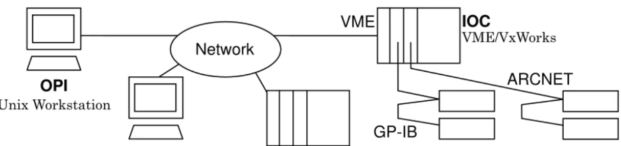
EPICS (Experimental Physics and Industrial Control System) is the software toolkit to construct control systems for scientific instruments such as accelerators, telescopes and other large experimental apparatuses. EPICS is developed and maintained by international collaboration. Figure 1 shows a typical configuration of the control system using EPICS. In general two types of computers are used in the EPICS control system. One is IOC (Input/Output Controller), the other is OPI (Operator Interface). IOC is the computer which directly controls the equipments through its own hardware connection to the equipments. OPI is the computer which runs various high level applications like operator interface. IOC and OPI are connected each other by LAN (Local Area Network) with IP (Internet Protocol). They constitute a distributed control system, where IOC provides control services, and OPI utilize them as clients. Thus, EPICS is suitable to the network distributed system.
One of the typical IOC is a VME (VERSAmodule Eurocard bus) single board computer. In this case, various types of VME interface boards are often used to connect to the devices. In historical reason VxWorks is often used as OS (Operating System) of the VME-based IOC. In this case, to develop the IOC software, generally host computer is necessary for cross development. Sometimes the host computer can be also OPI. Old EPICS (version R3.13 or older) supported only VxWorks as the OS of IOC. Current version (R3.14) supports multiplatform for IOC. Common OPI has been UNIX based workstation. Recently PC (Personal Computer) becomes popular, and Windows, Linux and Macintosh are also used as OPI.
The basic features of EPICS are IOC Database and Channel Access (CA). IOC Database is the core function of IOC. Channel Access is the basic communication protocol of EPICS. Detailed descriptions of these key technologies are given in the following sections.
Network
IOC
VME/VxWorks VME
ARCNET
Figure 1: a typical configuration of the control system using EPICS GP-IB
OPI Unix Workstation
2-2-1. IOC database
IOC Database is the memory resident database on IOC. It provides the core function of IOC. The database is defined as a set of records. Typically one record is corresponding to an input signal or an output signal. There is another type of record, which is not corresponding to input/output signal directly but holds internal state or executes some calculation. The record is identified by its name. Each record has its own record type and behaves according to its record type. Each record has a fixed set of fields, which is defined according to its record type. The field is the elemental unit for data access. The most important field is VAL field, which typically holds input/output data or the result of the calculation. Between records, you can define a reference, which is called link. Using link, data can be passed from one record to the other, or control its behavior. Defining IOC database is the basic procedure to construct the control system with EPICS.
2-2-2. Channel Access
Channel Access (CA) is the communication protocol between lower layer (IOC layer) and upper layer (OPI layer) or between lower layers. CA is based on client-server model. The unit of the data access is called channel. The channel is corresponding to the unit of data which is specified by "record_name.field_name". This name is called channel name, which identifies the channel. The client can execute read operation (get) or write operation (put) using channel name. The client does not have to specify the IOC on which the channel is resident i.e. the client does not have to know the server name. It can access the data only with the channel name. This simplicity is one of the advantages of Channel Access. There is another function called monitor. Using this function, the Channel Access server automatically sends a notification whenever the channel status is changed. At the client side, when the client receives the notice, registered callback routine is automatically called with the channel information including the new value, status and timestamp.
Thus, the procedure of the data access is very simple in EPICS. You do not have to consider the detailed implementation, like that what kind of device to be accessed, which computer to be communicated with, and so on. Only you need to know is channel name. EPICS provides such a simple method to users.
2-3. KEKB accelerator control system
As described before, the control system of TRISTAN has been fully replaced with the new control system using EPICS.
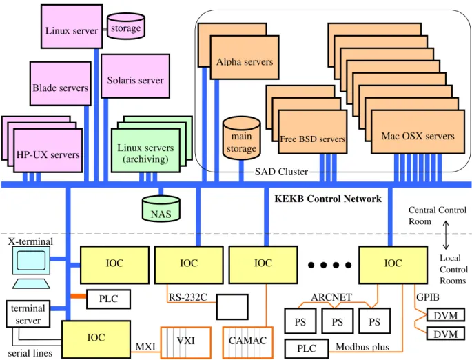
Figure 2 and Figure 3 show the schematic view of the control system of TRISTAN [1] [2] and KEKB [3] [4] [5] [6], respectively. The control system of TRISTAN consisted of HIDIC minicomputers, which were distributed along the accelerator ring and the network which connected them each other. These computers and network have been completely replaced with new ones because of the rapid progress of the technologies of the computers and networks since the TRISTAN control system was designed and constructed.
Figure 2: Original configuration of the TRISTAN control system; reproduced from reference [1].
Linux server
Alpha servers
Free BSD servers Mac OSX servers main
storage storage
IOC terminal
server
IOC IOC IOC
Central Control Room
Local Control Rooms KEKB Control Network
X-terminal
serial lines
Figure 3: schematic view of the KEKB control system SAD Cluster
DVM DVM GPIB PS
PS PS
ARCNET
PLC Modbus plus
VXI CAMAC
MXI
RS-232C IOC
PLC
NAS Linux servers
(archiving) HP-UX servers
Blade servers Solaris server
KEKB control system has been designed to use UNIX based workstations as OPI and VME computers as IOC. The VME computer and the devices to be controlled are connected through various types of field buses. The field buses in KEKB are CAMAC, ARCNET, VXI/MXI, GP-IB, RS-232C, and Modbus Plus, and so on. In contrast to TRISTAN control system, in which the field bus used was CAMAC only, it is the distinctive feature of the KEKB control system to adopt various field buses.
2-3-1. IOC in KEKB
Figure 4 shows a typical VME computer in the local control room in KEKB. The VME subrack with the power supply module and cooling fan modules has a single board computer and several interface boards to control various field buses. Usually the system monitoring module called RAS is also mounted in the subrack. The RAS monitors power lines, temperature of the flowing air and status of the cooling fans. The RAS can also
reset the VME computer. Because the RAS has the serial communication line which is independent of the board computer, operator can reboot the VME computer remotely when the VME computer became hang-up. All of the VME computers in KEKB adopted VxWorks as real-time operating system (OS).
Figure 4: a typical VME computer installed in the local control room
At the beginning of the operation of KEKB, only VME computers were installed as IOC. Later the computers other than VME have been gradually installed because EPICS R3.14 has been released and it allows the OS other than VxWorks for IOC, thus, we can choose wide variety of the platforms for IOC. The most frequently used non-VME type computers in KEKB are PC-AT/Linux. It is inexpensive and easy to construct IOC. Another popular platform in KEKB is F3RP61, which is the CPU module of the Yokogawa FA-M3 series PLC (Programmable Logic Controller). It support Linux and EPICS can run on it. Recently F3RP61 becomes intensively used in KEKB.
For the case of magnet power supply, only VME computers are used. Each power supply building has a local control room and one IOC for magnet power supplies is assigned to each local control room. Thus, the 8 IOC’s for LER and HER, and 3 IOC’s for BT are installed. 8 IOC’s for LER and HER are dedicated IOC to magnet power supplies,
but 3 IOC’s for BT are not only for magnet power supplies but also for other components of BT. We also have one special IOC in the central control building which is used for the overall control of magnet power supplies.
2-3-2. Control network
In KEKB backbone system of the control network consists of the optical fibers between central control room and local control rooms. At the beginning 100Mbps FDDI was adopted for the backbone line and FDDI GigaSwitch was installed at the central control room. The branch line within the local control room has been 10Base-T Ethernet. Later because of the advances in Ethernet technology, it becomes unfavorable to maintain FDDI system both in the cost and in the performance. Thus, another backbone system using Gigabit Ethernet has been installed and gradually migration has been done. Currently the migration has been completed and the FDDI system has stopped.
2-3-3. OPI layer
In KEKB various types of computers have been installed in the OPI layer. They can be classified into the following 3 categories in the operational view.
(1) General purpose servers for the control system (2) SAD Cluster machines (servers for operation) (3) Special purpose machines
The general purpose servers for the control system are the UNIX based server workstations installed in the central control building. At the beginning one HP-UX server has been installed. It has been used to run higher level application for the operation and also used for the development and the management of the IOC software, file management, RDBMS (Relational Database Management System) server, and so on. Later the second HP-UX server has been installed. In 2006 2 new servers (Sun/Solaris, Linux) has been installed. Currently this Linux server is the main server of the KEKB control system. After that additional HP-UX server and blade server system have been also installed.
Apart from these servers the group of computers called SAD Cluster is also used to run the application programs for operation. These applications are mostly written in SAD Script. SAD (Strategic Accelerator Design) is a computer program complex for accelerator design developed in KEK since 1986. Originally SAD Cluster machines have been served for the modeling calculation of accelerators. Since the commissioning of
KEKB, they also have served for operation programs of KEKB. By the historical reason, not only KEKB but also other accelerator users use SAD Cluster. The programs that are not related to KEKB operation also run. Therefore, SAD Cluster is managed separately from the control group and operated separately from the general purpose servers for the control system. SAD Cluster consists of various architectures of computers. They are HP-UX, Alpha/Tru64 UNIX, Linux, Macintosh and FreeBSD in historical order. (HP-UX machines and Linux machines have been discarded.)
Apart from category (1) and (2), several computers have been installed for special purposes. For example, there are 3 Linux servers that are dedicated to run archive program called KEKBLog. It collects various monitoring data and setting data and archives them during operation of KEKB accelerators. Because it is required to run uninterrupted, the dedicated servers are assigned to it. Such special purpose machines are managed by each manager separately.
3. Development of the interface to the magnet power supply
It is important how the interface between the IOC and the magnet power supply is designed, because it determines the characteristics of the control system of the magnet power supplies of KEKB. In this chapter the detailed design and development of the interface are described. Overall configuration of the control system of the magnet power supplies is also described.
3-1. Prerequisites of the design of the interface
As described before, KEKB storage rings are characterized by a large number of magnet power supplies. Especially more than 1700 small power supplies whose rating current is 10A or less have been installed. For a large number of such a small power supply, the cost of the production is important. Therefore, the cost reduction of the interface is also required.
About the speed of the interface, no stringent requirements have been imposed because the magnets in KEKB are basically controlled in DC operation. The only requirement is that the control speed should catch up the speed of operators. More detailed discussion about the speed of the interface is shown in section 3-4-1.
3-2. Consideration of the CAMAC system of TRISTAN
In the TRISTAN control system, CAMAC was adopted as the unified interface for all of the accelerator components. Therefore, the interface for the magnet power supply was also CAMAC. CAMAC crates were installed in the local control room adjacent to the power supply room. The CAMAC crate was connected to the control computer (HIDIC) through a serial highway. The signal lines between CAMAC modules and the magnet power supplies were relayed by the terminal blocks.
At first, the reuse of the CAMAC system of TRISTAN was one of the candidates for KEKB. But it was finally excluded from our choices because of the following reasons.
(1) Because a number of the magnet power supplies increases significantly, the stocks of the components of the CAMAC system were insufficient. Therefore, adding the components like CAMAC modules, crates, crate controllers, and so on, was necessary. But they were expensive.
(2) The amount of the wiring for the signal lines from the CAMAC module to the magnet power supply was large.
(3) The system had various components, which were serial highways, crate controllers, crates, various kinds of modules, terminal blocks, and so on. Therefore, the maintenance load seemed to be heavy.
(4) If the magnet power supplies of TRISTAN continued to be used, the CAMAC system including the wirings could be also used without rewiring. For an example, the low level RF systems of TRISTAN have continued to be used for KEKB. In this case its interface has also continued to be CAMAC and rewiring has not been necessary. But for the magnet power supply case, almost all magnet power supplies were not reused. Exceptions are only 8 power supplies. For such situation, the reuse of the CAMAC was not so advantageous.
3-3. Serial communication for the interface
Instead of the CAMAC system, we have considered the system which utilizes serial communication in order to reduce the amount of wirings. The serial communication was also used in TRISTAN for the connection from the control computer (HIDIC) to the crate controller. The idea is that serial communication can be applied from the control computer (IOC) directly to the magnet power supply. It seems to greatly simplify the system configuration.
There are many systems of the serial communication. There are advantages and disadvantages to each system. Here the following three representative examples are being considered.
(1) RS-485 asynchronous serial communication (2) CAN bus
(3) ARCNET
The asynchronous serial communication is a simple method and can be easily controlled by computers. Because the built-in serial interface in the embedded microcomputer can be used for this purpose, the hardware can be simple. On the other hand because the unit of the communication is a byte, you need to design and implement your own higher level communication protocol than byte transfer.
CAN (Controller Area Network) bus is the serial communication which is developed to reduce wirings. Because the unit length of the data transfer (packet length) is rather short, it is suitable for the case that the simple short commands are frequently passed, but it is not so suitable for transferring the large amount of data. As described later, transferring several kilobytes data is required for the KEKB magnet power supply control system in order to send the tracking data which are used for the synchronization
among multiple magnet power supplies.
ARCNET (Attached Resource Computer NETwork) is a token passing network. It supports relatively long packet (up to 512 bytes) and communication speed is enough (up to 10Mbps) for the KEKB magnet power supply control system. Because the controller chips on which the communication protocol is implemented are available, it is easy to construct the system. The ARCNET supports several kinds of signal transmission media. Among them twisted-pair cable driver is supported with HYC2485 media driver. This configuration allows multi-drop wiring. Up to 20 ARCNET nodes can be connected on a single network segment in a daisy-chain manner.
As the result of the comparison we have decided to adopt ARCNET for the KEKB magnet power supply control system, so that we has greatly reduced the amount of signal cables.
3-4. Synchronous operation of the multiple magnet power supplies
In KEKB rings, because the energies of the injection beams are equal to the stored beam energies for the collision, acceleration operation is not necessary. Therefore, the synchronous ramping of the magnet power supplies for the acceleration is not required. But the synchronous changing of the multiple magnet power supplies is still required in order to perform the following examples of operations keeping the stored beam stable.
(1) Setting multiple steering magnets in order to make local bump orbit (2) Changing multiple quadrupole magnets to change betatron tune (3) Changing steering magnets over the whole ring for the orbit feedback (4) Changing the optics
(5) Changing the beam energy for the energy scan
Thus, efficient operation to change the magnetic fields of the magnets with the stored beam being kept stable is required in KEKB. Therefore, the mechanism to set currents of more than two magnet power supplies synchronously with each others should be implemented in the control system.
3-4-1. The required specifications of the synchronous setting
The required specifications of the synchronous setting of the magnet power supplies have been given by consideration of the model case assuming some operations of the magnets. We, operation group, have discussed the tolerance of the synchronization error and the time to be allowed for setting as the requirements. These requirements have
become one of the guidelines for designing the magnet power supply control system. The detailed discussions are given below.
Firstly for the operations with corrector dipoles, most frequent operation is assumed to be the setting bump orbit for the lattice diagnostics. Therefore, a model case of the operation of the bump orbit is assumed as followings. The assuming bump height spans
±10mm. The corresponding kick angle of the corrector dipoles spans ±0.5mrad. The span is equally divided to 8 steps and the bump orbits are set at the 9 points. Then orbit measurement follows at each point. Each orbit measurement is assumed to take 1 second. Therefore, the desirable setting time of each bump orbit is also 1 second or less. Thus, according to this model, they have imposed the following requirement.
Change speed of the corrector dipole 0.125mrad/sec (Condition-1)
Then the bump orbit consists of at least 2, sometimes 8 corrector dipoles. The setting current of these corrector dipoles must be changed synchronously each others. The tolerance of the synchronization error per one corrector dipole ⊿θ is estimated from the following requirements.
(1) No beam loss ⊿θ 1mrad/√8
(2) Displacement at IP is less thanσy*/4 ⊿θ 1.1μrad/√8 (3) Deviation of the betatron tune is less than 3×10⁻⁴ ⊿θ 1.2μrad/√8 (4) Deviation of the orbit length ⊿L/L 1×10⁻⁷ ⊿θ 0.3mrad/√8 Among them (2) and (3) are dominant (but not required if the bump orbit is just for the lattice diagnostics). Thus, the following guideline has been imposed.
⊿θ 1μrad/√8 (Condition-2)
Secondly for the operations with quadrupole magnets, several requirements have been also discussed. However, they are less severe than these conditions of the corrector dipoles.
Under the conditions discussed above, the requirements on the synchronous operation have been considered. In order to suppress the synchronization error, amount of the change of the corrector dipole within one tracking step should satisfy the Condition-2. Because total amount of the change of the corrector dipole is 0.125mrad in the model, the Condition-2 requires that a number of tracking steps of the synchronous operation needs to be about 354 steps or more. Including margin, more than 400 steps is considered to be desirable guideline. Thus, the following condition has been defined as the guideline for designing the control system.
Case of 8 corrector dipoles to be changed 0.125mrad synchronously within 1
second (Asummption-1)
Setting current with 400 steps per second has to be done under the Assumption-1. (Condition-3)
Then the time to be allowed for the synchronous operation has been considered. The original requirement from the operation group is that setting bump orbit should be completed within 1 second. This time includes not only the time of changing current of the magnet power supplies but also the time consumed by the control system like as the time of calculations, the time of the data transfer, and so on. However, the changing current takes up to 1 second because of the response characteristics of the magnet power supply. Therefore, no time is left for the control system if the requirement is strictly imposed. Then we, control group, have redefined the requirement that the time for control system should be small enough compared to 1 second. Thus, the following condition has been also defined as the guideline for designing the control system.
The time for control system should be less than 0.1 second under the Asumption-1. (Condition-4)
3-4-2. Implementation of the synchronous setting
The procedure of the synchronous setting takes following steps in sequence. First the tracking pattern of the current is calculated for each magnet power supply. Then synchronous change of the current along the pattern is performed. In the digital control system, in order to change the current, it seems natural way to digitize the time. In other words, the time axis is divided into the steps with the constant short time interval, and then the corresponding current is set at every step.
It has been the key point of the system design that how the synchronous setting is implemented using the serial communication interface between the IOC and the magnet power supply. Following 3 methods of the synchronous setting have been considered.
(1) The IOC sends a value of the setting current to the magnet power supply every step. The synchronization is done by the IOC. The role of the magnet power supply is just doing D/A conversion of the received value and then outputting. (2) The IOC does not send a value of the setting current every step, but sends only the
final setting value to the magnet power supply. The magnet power supply generates the tracking pattern from the final setting value, and then sets the current according to the pattern with the interval clock. For the synchronization,
some mechanism to deriver the synchronization signal to the magnet power supply is necessary.
(3) The generation of the tracking pattern is done by IOC. The generated data are sent to the magnet power supply. The magnet power supply receives the data and temporarily stores them, and then sets the current according to the stored data with the interval clock. For the synchronization some external signal is necessary to trigger the start of the setting current. (Figure 5 shows the timing chart.) In case of (1), the magnet power supply does not have to have the complex mechanism. On the other hand, the interface is required of the real-time response. Because ARCNET supports real-time communication, this method is possible in principle. However, the careful system design is necessary in order to achieve the required response. For an example, the configuration of the ARCNET interface should be carefully tuned. In case of (2) and (3), the real-time response of the interface is not required. On the other hand, the magnet power supply needs to be more intelligent. Especially in case of (2), complex calculation to generate the tracking pattern is required. Such a complex function is assumed to be implemented on the embedded microcomputer. However, considering the maintenance, for example adding functions or performance improvement, it is better to implement such function as the software of the IOC than as the embedded firmware of the magnet power supply because the software of the IOC is more flexible and easier to upgrade than the embedded firmware.
As the result of the comparison we have decided to adopt the case of (3) because it is considered to be the most well-balanced method. In case of (3), the configuration of the ARCNET interface can be flexibly designed because the real-time response is not required. In addition, although the magnet power supply is still required to handle the array data of the tracking pattern, the function to be implemented on the magnet power supply is rather simple because the complex calculation to generate the tracking pattern is done by the IOC instead of the magnet power supply. There are two disadvantages of the case of (3). First, it needs communication time to transfer the tracking data beforehand. Second, it needs an extra wiring for the synchronization signal. Assuming a practical configuration of ARCNET, the communication time has been estimated and then it has been confirmed that Condition-3 and Condition-4 are satisfied even in the case of (3). Therefore, the communication time is not so severe problem. And we have concluded that the amount of additional wiring is not so large and tolerable compared to its advantages.
min. 1 ms tracking pattern calculation on IOC
data transfer through ARCNET synchronous start signal
output current
max. 4096 steps
Figure 5: sequence of the synchronous setting in the method (3)
3-5. Delivery system of the synchronous start signal
The synchronous start signal, which triggers setting current to start, is delivered by the event timing system from the central control room to the local control room in the power supply building. From the local control room to each magnet power supply, the synchronous start signal is delivered using the same cable of ARCNET.
The synchronous start signal just defines the start timing of setting current. After the start, the timing of each step is defined by the internal clock in the magnet power supply.
3-5-1. Event timing system
Figure 6 shows the event timing system in KEKB [7] [8]. The event timing system is VME based system and consists of an event transmitter module (EVT), event distribution modules (EVD) and event receiver modules (EVR). These modules are connected by optical fibers to transfer the timing signals. The VME computer named IOCTMCCC is installed in the central control room, which has 1 EVT and 4 EVD. The event signal is generated by the EVT and relayed by the EVD and then sent to each local control room through the optical fiber. At each local control room, the event signal is received by the EVR.
The event timing system is not only used for the synchronous setting of the magnet power supplies, but also used for the synchronous measurement of the beam position monitors (BPM). Therefore, the EVR is plugged in the VME computer (IOC) of the BPM
control system in each local control room. Whenever the EVR receives the event for the synchronous setting, it output a TTL level pulse signal as the synchronous start signal. The event codes for the synchronous setting are assigned independently for LER and HER, and the EVR outputs two synchronous start signals for LER and HER.
Figure 6: event timing system in KEKB; reproduced from reference [8].
3-5-2. Delivery of the synchronous start signal from the IOC to the magnet power
supply
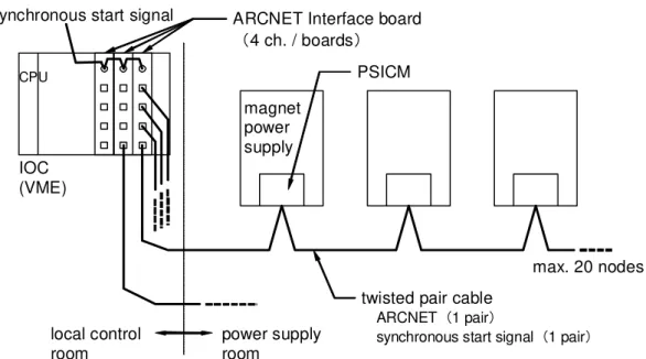
Figure 7 shows the delivery system of the synchronous start signal in the local control room. From the IOC of the magnet control system to the magnet power supply, the synchronous start signals are delivered not through the dedicated cables, but through the cables combined with ARCNET. STP (Shielded Twisted Pair) cable is used for ARCNET in KEKB. The STP cable is Category 5 and has 4 twisted pairs. Because only one pair is necessary for ARCNET, one of the unused pairs is assigned to the synchronous start signal.
The synchronous start signal from the EVR is sent to the ARCNET interface VME-modules in the IOC of the magnet control system in each local control room, and then the signal is buffered and delivered to the magnet power supplies through the cable combined with ARCNET.
ARCNET Interface board 4 ch. / boards
IOC (VME)
power supply room
local control room
magnet power supply
PSICM
twisted pair cable ARCNET 1 pair
synchronous start signal 1 pair synchronous start signal
max. 20 nodes
CPU
Figure 7: delivery of the synchronous start signal with ARCNET
3-6. PSICM
The magnet power supply is required to have the ARCNET interface and required to accept the commands from the IOC. For this purpose, the magnet power supply is required to have an embedded microcomputer and control software (firmware). In the initial plan, these mechanisms were planned to be the inseparable built-in functions of the magnet power supply and to be included in the specification of the magnet power supply for the production. However, because of the following reasons, the final design has been decided that the separate board which has the ARCNET interface and the microcomputer has been developed and produced independently from the magnet power supply. The board is designed as the plug-in module in the magnet power supply as shown in Figure 8a. This module has been named PSICM (Power Supply Interface Controller Module) [9]. The PSICM mounted in a magnet power supply is shown in Figure 8b.
(1) There have been several makers expected to produce the magnet power supplies. We considered that the quality control is easier to develop and provide a unified interface module than to implement the functions separately in each maker. (2) Considering the upgrade of the firmware, it seems easier to have only one kind of
firmware, i.e. the unified module.
(3) When the PSICM fails, it is easy to repair by replacement. This is an advantage of the plug-in module for the maintenance.
The PSICM has a DIN 64-pin connector which connects to the magnet power supply. The signals through the connector are TTL level. The basic communication with the magnet power supply is the 16 bits parallel I/O. It has 5 bits address lines to specify the contents of the I/O data. It also has 7 dedicated signal lines, which are used to send some pulse signals to control the magnet power supply. The basic hardware parameters are listed in Table 3.
Table 3: basic parameters of PSICM [9]
Physical size 100mm x 160mm x 6 HP
Network connectors 2 x RJ45 STP connectors Signal connector DIN 64-pin connector
Microcontroller AM186 16-bit Microcontroller
Clock frequency 20MHz
Data memory 256kB SRAM(128kB x 2)
Program memory 256kB EPROM (128kB x 2)
Power required +5V 0.4A
Network interface 2.5Mbps ARCNET
Interface to magnet power supply 7 bits TTL momentary output 16 bits TTL parallel output to DAC
16 bits TTL parallel I/O with 5 bits address
Figure 8a: PSICM
Figure 8b: PSICM mounted in the magnet power supply
Although the PSICM is designed for the interface of the magnet power supply, the hardware design is considered to be general purpose. Therefore, it can be also used for the interface of other devices by changing its firmware. In fact in KEKB, the PSICM is also applied for the control of the video signal switchers and for the status readout of the beam abort requests.
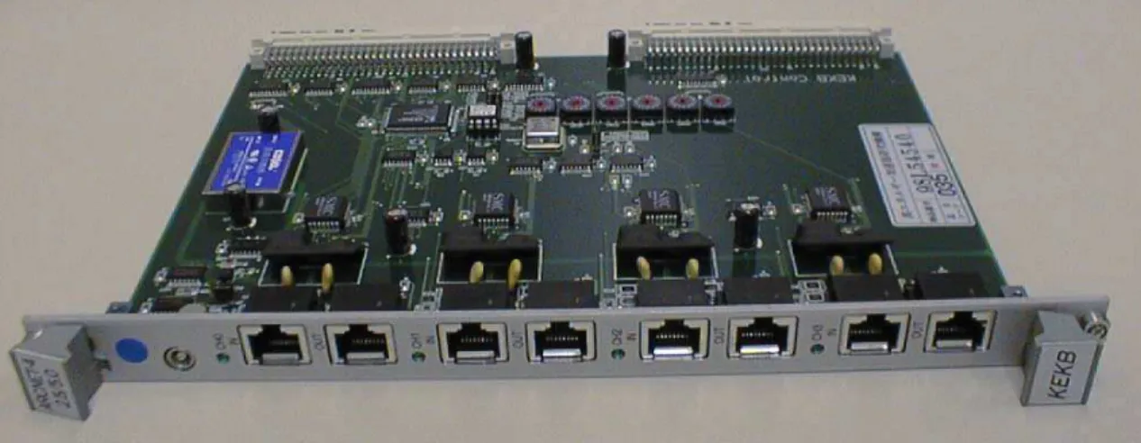
3-7. ARCNET interface VME module for the magnet power supply
As the IOC side, the VME module for the ARCNET interface has been developed. This module has the following features as compared to the commercially available ARCNET
interface modules because it is dedicated to the KEKB magnet power supplies. (1) One module has 4 channels of the ARCNET interface for the density. (2) The media driver of the ARCNET is only fixed to HYC2485.
(3) The connector for the ARCNET is RJ-45 for STP.
(4) The module accepts the synchronous start signal and distributes it after buffering. The photo pictures of the module are shown in Figure 9a and 9b.
Figure 9a: ARCNET interface VME module
Figure 9b: ARCNET interface modules mounted in the VME subrack
3-8. ARCNET hub for the magnet power supply
In the initial plan, one ARCNET segment was planned to connect up to 20 PSICM. But later the large segment has been divided into two segments by installing a hub to reduce the number of connected nodes per segment in order to keep good stability of the communication. Figure 10 shows an example configuration of the ARCNET before and after introducing the hub.
Because the split of the synchronous start signal is also required for the KEKB magnet power supply, the commercially available ARCNET hub can not be applied without modification. Therefore, the dedicated hub has been developed for this purpose. In ARCNET system, the controller chip for hub is available. Using this chip, 4 channels hub can be produced easily. We have developed the hub box which includes 3 sets of 4 channel hub. In the actual configuration, the hub box has been applied to the small magnet power supplies, which are mounted in the rack with high density. Typically 16 to 20 small magnet power supplies have been mounted in one rack and the rack was corresponding to one ARCNET segment. Figure 11 shows the hub box mounted in the rack.
IOC
IOC
Max. 20 nodes can be connected in a single ARCNET line.
hub
ARCNET (driven by RS485 differential driver)
ARCNET hub separates 3 (or more) shorter segments.
They are electrically separated, but logically form single network. The hub allows more stable operation.
Figure 10: typical configuration of the ARCNET before and after introducing hub
Figure 11: hub box mounted in the rack
3-9. Entire configuration of the magnet power supply control system
Looking at the overall design of the control system for the KEKB magnet power supplies, the ARCNET is the most important communication channel while some other communication channels are also used auxiliary [10]. Figure 12 shows the entire configuration and information flows of the magnet power supply control system including these auxiliary subsystems.
PSICM IOC for the magnets in each local control room
Asynchronous setting
Synchronous poles change server
IOCMGCCC (Global parameters)
IOCMGD08
IOCTMCCC IOC for BPM
in each local control room
Interlock system (PLC) Scanner
and DVM
Synchronous setting server Application programs
Magnet
interlock status
External interlock Magnet power supply
Current monitor (analogue)
ARCNET OPI (UNIX based servers)
Synchronous setting Status
EVR EVT / EVD
Synchronous start signal GPIB
Modbus Plus
Figure 12: entire configuration of the magnet power supply control system
3-9-1. Current monitor system of the magnet power supply
Although the communication path between IOC and magnet power supply is designed to be concentrated on the ARCNET as much as possible, there is an exception that the readout system of the current monitor of the magnet power supply is independently designed without ARCNET. If the readout of the current monitor is included in ARCNET, analogue to digital conversion is required within the magnet power supply (or within the PSICM). On the other hand, readout speed is not required but precise measurement is required for the current monitor system. Therefore, the high precision ADC (Analogue to Digital Converter) is required. Embedding such a high precision ADC in every magnet power supply is not good scheme in cost, especially for a large amount of small magnet supplies.
Instead of the embedded ADC, a practical system has been developed. Figure 13 shows the schematic view of the system. In this system the magnet power supply outputs the current monitor as the analogue voltage signal. The voltage signal is rotated by the scanner and measured by DVM (Digital Voltmeter). In this system, the scanner and the DVM are commercially available products. Using the scanner, one DVM measures 80 magnet power supplies. Such a system is not suitable for high-speed reading but high-precision measurement can be achieved at relatively low cost. The IOC
controls and reads the scanner and the DVM through GP-IB.
ARCNET Interface board 4 ch. / boards
IOC (VME)
power supply room
local control room
magnet power supply
PSICM
ARCNET cables (twisted pair) CPU
DVM
current monitors GPIB
scanner
Figure 13: current monitor system of the magnet power supply
3-9-2. Interlock signal from the magnet
Typically each magnet has a water flow sensor and a temperature sensor, which are used for the interlock system in order to cut off power when they detect anomaly. The interlock system has been implemented by the PLC (Programmable Logic Controller). All of the signals from the sensors are input to the PLC and aggregated, and then the PLC outputs the interlock signals, which are accepted by the magnet power supplies as the external interlock. The interlock status of the magnets can be read from the PLC. The interlock system is the independent system and has one connection point to the EPICS-based controls system at the D8 power supply building. The IOC of the magnet control at the D8 local control room is the only IOC which is directly connected to the Modicon PLC of the interlock system. They are connected through Modbus Plus [11].
4. Development of the control software
In this chapter the detailed features of the control software are described [12]. Because the KEKB magnet power supply control system is the distributed control system, the key point of the software design is that how the functions are divided and distributed over the layers. At first this point is discussed. Then each description of the developed software follows. Finally the implementation of the IOC software is also described.
4-1. 3-layers scheme of the distributed control system
In EPICS generally speaking, two types of computers are used, IOC and OPI. The IOC is the frontend computer directly connected to the devices being controlled. The OPI is the higher level computer which runs the application programs like operator interface. In the KEKB magnet power supply control system, PSICM also has microcomputer and software (firmware). Therefore, the control software is distributed over the 3 layers of OPI, IOC and PSICM. They have been designed to work cooperatively to achieve the required functions.
4-1-1. Software of the PSICM layer
The software on the PSICM is required to perform following functions. (1) Sending and receiving a packet of the ARCNET
(2) Parsing and executing the commands from the IOC (3) Accepting external trigger signal to start setting DAC
(4) Setting DAC of the magnet power supply at every step driven by the internal clock
(5) Sending the status of the magnet power supply and the PSICM itself to the IOC
(6) Changing the internal state according to the status change of the magnet power supply
(7) Diagnostics functions of the ARCNET and PSICM itself
The software on the PSICM is resident in the ROM (Read Only Memory). Therefore, it is not desirable to update frequently. Thus, the software on the PSICM has been designed to be as simple as possible in order to reduce the probability of the update. The specification of the PSICM software has been defined according to the following guidelines.
(1) The commands from the IOC are designed to be as simple as possible. It is not desirable that single command causes complex work. Most of the commands are designed to execute a simple atomic function. Therefore, in order to perform the complex work, the IOC is required to send the combination of the atomic commands.
(2) The PSICM is designed to send no acknowledgements to the IOC for every received command. Instead The PSICM sends status packet frequently to the IOC. The status packet also includes all internal states of the PSICM. Thus, the IOC can recognize whether the bunch of commands are normally completed or not by analyzing the status packet from the PSICM. The frequency of the status packet can be flexibly configured.
4-1-2. Software of the IOC layer
Software of the IOC layer is the major part of the magnet power supply control system. The implementation of the IOC software is based on EPICS. The control points of each magnet power supply are implemented by defining EPICS records in the IOC database. Table 4 shows the major records with their functions. The most important function is the setting function of the output current of the magnet power supply individually. The IOC software has been cross-developed on the central control server and is downloaded from the central control server at the boot up time. This scheme is convenient for the maintenance of the software, such as adding or changing its functions, because all of the IOC software can be centrally managed on the server. The IOC software has been still updated a couple of times per year since the beginning of the operation of KEKB. The individual operation on each magnet power supply is implemented on the IOC layer, while the operation in which more than two magnet power supplies participate, such as the synchronous setting, is not completed in the IOC software but also needs the participation of the central control server.
Table 4: major record for each magnet power supply Record name *1, *2 Function
header:name:IDIR Direct setting in current header:name:ISEQ Sequence setting in current
header:name:ISST Simple standardize setting in current header:name:ISTD Standardize setting in current
header:name:KDIR Direct setting in control-K-value header:name:KSEQ Sequence setting in control-K-value
header:name:KSST Simple standardize setting in control-K-value header:name:KSTD Standardize setting in control-K-value
header:name:IRB Read back of set value in current
header:name:KRB Read back of set value in control-K-value header:name:PRB Read back of set value in beam momentum header:name:VMON Raw value of output monitor (voltage of DVM) header:name:IMON Output monitor in current
header:name:KMON Output monitor in control-K-value header:name:PMON Output monitor in beam momentum
header:name:CMD Command code
header:name:AF Fudge factor a
header:name:BF Fudge offset b
header:name:THETA Design angle
header:name:REQSTAT Requested status of setting header:name:REQVAL Requested value of setting
header:name:REQPOL Requested polarity
header:name:REQU Requested digital set value header:name:STATE State of setting sequence header:name:ALARM Alarm status bits
header:name:RC Return code of setting
header:name:STATUS Status array from the PSICM
header:name:SHREG SH register (status bits of magnet power supply) header:name:SSREG SS register (internal state of PSICM)
header:name:CREG C register (digital set value) header:name:DREG D register (raw value of DAC) header:name:IREG I register (interlock bits)
header:name:IPREG IP register (primary interlock bits) header:name:SDCOUNT Loop counter of standardize
header:name:SET_PREC Tolerance of monitor error form set value header:name:MAKE_PKT Internal record: subroutine for control logics header:name:SEND_PKT Internal record: ARCNET packet to PSICM
*1: “header” is major category; for example “MGLPS” for LER magnet power supply.
*2: “name” is individual name of the magnet power supply.
4-1-3. Software of the OPI layer
As described before, the central control server is used not only for the development of the IOC software but also used for running the higher-level application programs, such as the operator interface panels for the accelerator operations. As the higher-level application programs have been written typically by the people in the commissioning group, they are considered to be user application programs from the view of the control system. Some actual examples of the application programs which have been used in KEKB accelerators are shown in chapter 5. The server program for the synchronous setting is also run on the central control server. The synchronous setting server program is located between the application programs in the OPI layer and the IOC layer. The synchronous setting server is responsible for the arbitration among the multiple magnet power supplies and provides the API (Application Programming Interface) of the synchronous setting to users.
4-2. Required functions for the magnet power supply control software
There are two categories of the required functions for the magnet power supply control system. One is the basic function, while the other is the advanced function. The basic functions are the remote control of the atomic operations like power on, power off, reset interlocks, status readout, setting current, monitoring current, and so on. They are minimal functions and definitely indispensable. However, in order to support the operation of the complex system like accelerators, it seems insufficient to provide only such low level operations which correspond directly to the hardware functions. Therefore, we have decided to incorporate the following functions into the magnet power supply control system beforehand in order to support the efficient operations and the efficient development of the user application programs in KEKB/PF-AR.
(1) The translation from the magnetic field to the current for the setting operation should be incorporated into the setting operations.
(2) The regular sequence of the setting current to reduce the magnetic hysteresis error should be supported.
(3) Synchronous setting of the multiple magnet power supplies should be supported.
(4) For PF-AR, the pattern operation of the acceleration or any other pattern should be easily carried out. The pattern should be flexibly configured.
4-3. Control parameter
4-3-1. Magnetic field as the control parameter
In the view of the hardware device, the control parameter of the magnet power supply is current. However, in the view of the operation of the accelerator, the parameter to be controlled is not the current of the power supply but the magnetic field of the magnet. Considering the optics of the accelerator, it is desirable to control the magnet system with the parameter called K-value, which is a kind of abstracted parameter of the magnetic field normalized by the beam momentum. Therefore, we have decided to develop the translation service between the current and K-value, which is implemented as a part of IOC software.
In order to translate from K-value to magnetic field, the beam momentum is necessary. Therefore, the software variables which hold the value of the beam momentum have been introduced. The variable has been implemented as an EPICS record. The record is defined not for every magnet power supply. All magnet power supplies of one storage ring share one momentum record.
In case of bending magnet, K-value is equivalent to the bending angle of the beam orbit. Usually the bending magnet has its own design angle. In actual operation, sometimes the bending magnet is set to the value which is slightly deviated from the design angle. Therefore, it seems convenient to adopt the amount of deviation from the design K-value as the control parameter instead of the K-value itself. Here the deviation value is called “control-K-value”. For dipole magnets, following equation defines the control-K-value.
(control-K-value) = (K-value) – (design angle)
For steering magnet, usually the design angle is zero. For quadrupole and sextupole magnets, control-K-value is defined equal to K-value because they have no design angle. Originally the K-value is the property of each magnet. However, in actual operation, the K-value is controlled by the current of the power supply. Therefore, it is necessary to define the K-value (and control-K-vale) also for the magnet power supply. In KEKB/PF-AR, when more than 2 magnets are driven by one magnet power supply, the K-value of the magnet power supply is defined not by the sum of all magnets but by the averaged value per one magnet.
Introducing the control-K-value as the control parameter, the magnets and magnet power supplies can be treated without considering the low level hardware characteristics of the magnets when you write the higher-level application programs.

![Figure 2 and Figure 3 show the schematic view of the control system of TRISTAN [1] [2]](https://thumb-ap.123doks.com/thumbv2/123deta/6152470.102925/15.892.137.764.489.862/figure-figure-schematic-view-control-tristan.webp)

![Figure 6 shows the event timing system in KEKB [7] [8] . The event timing system is](https://thumb-ap.123doks.com/thumbv2/123deta/6152470.102925/26.892.150.729.186.429/figure-shows-event-timing-kekb-event-timing.webp)
![Figure 6: event timing system in KEKB; reproduced from reference [8].](https://thumb-ap.123doks.com/thumbv2/123deta/6152470.102925/27.892.131.765.242.630/figure-event-timing-kekb-reproduced-reference.webp)
![Table 3: basic parameters of PSICM [9]](https://thumb-ap.123doks.com/thumbv2/123deta/6152470.102925/29.892.145.746.339.672/table-basic-parameters-of-psicm.webp)