An Approach for Verification Assertions Reuse
in RTL Test Pattern Generation
Maksim Jenihhin
1, Jaan Raik
1, Hideo Fujiwara
2, Raimund Ubar
1, Taavi Viilukas
11Tallinn University of Technology, Estonia 2Nara Institute of Science and Technology, Japan
Abstract
Assertions are used in functional verification of design to detect design errors. In this paper we propose an approach for their reuse in manufacturing test pattern generation at Register-Transfer Level (RTL) for non- scan designs. The proposed approach provides for fault coverage increase and speed-up of test generation process. The discussed case-study demonstrates the feasibility and effectiveness of the proposed idea.
1. Introduction
Test pattern generation for the today’s sequential circuits is lacking satisfactory methods and remains to be a challenge for both industry and academia. One of the wide spread solutions used by the community at present is substitution of the hard test pattern generation task by theoretically much simpler approach relying on scan-paths together with combinational Test Pattern Generation (TPG). However, the scan-path methods have their shortcomings including increased area, delay and consumed power. It also causes targeting of non- functional failure modes, which results in over-testing and yield loss. In the rest of the paper we will consider circuits under test without scan chains or other DFT (design for testability) solutions.
To cope with the TPG problem a number of approaches have been proposed. Some of them i.e. the ones targeting deterministic TPG at the gate level [7] can efficiently handle sequential designs of even a couple of thousands of gates. The simulation-based approaches [8] cannot guarantee detection of hard-to- test faults. The fundamental shortcoming of the functional test generation approaches [9] that rely on functional fault models is that they do not offer full structural level fault coverage. Hierarchical and RTL test pattern generation has been proposed [10] as a promising alternative to target complex sequential circuits. The published works include implementing assignment decision diagram models [11] combined with SAT methods to address register-transfer level test pattern generation.
In [1] and [2] we have proposed a hierarchical constraint-based TPG for RTL designs. Its advantages
as well as some limitations will be discussed in more details in the next section.
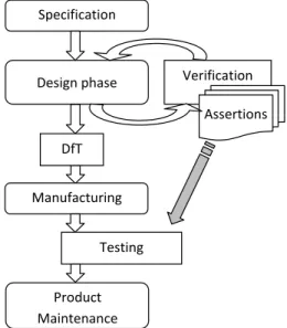
In this paper we propose to have a broader look at the discussed above problem of TPG for manufacturing test. The preceding phases of an ASIC development flow (Figure 1) normally include the design phase which is tightly coherent with the functional verification process targeted at design errors. The main goal of the functional verification is to insure the functionality of the design implementation (normally expressed by means of hardware description languages i.e. HDLs) corresponds to the requirements of the specification prior the synthesis phase. The verification process can rely on both formal and simulation-based approaches. The verification is a hard task by itself and intensive research goes in this area as well. One of the efficient strategies used in verification is application of assertions [3], which are pieces of a design explicitly specified behavior and aimed at design hard to verify parts. The recent emergence and success of such assertion specification languages as PSL (Property Specification Language) [4] and SystemVerilog [5] is an important step in assertion-based verification methodology development. The assertions can be used in both formal and simulation-based verification
Figure 1. ASIC development flow Specification+
Design+phase+
Product+ Maintenance+
Verification+ Assertions+
Testing+ DfT+
Manufacturing+ +
11th IEEE Workshop on RTL and High Level Testing (WRTLT'10), pp. 107-110, Dec. 2010.
approaches, however normally they are cleaned out from the HDL code once the verification process is finished and the design is sent for synthesis.
The approach we propose in this paper considers reuse of the information functional verification assertions contain for TPG targeted at structural manufacturing test. One of the important observations here is that normally the assertions are written by the design engineer who has a deep understanding of the design’s functionality.
In [6] we have discussed the ideas for verification assertions reuse directions very generally.
In [12] and [13] the authors address hardware checkers generation from assertions targeted to aid manufacturing testing.
As opposed to the mentioned approaches we consider assertions as extra information for deterministic TPG targeted at RTL non-DFT designs.
The rest of the paper is organized as follows. Section 2 describes the existing hierarchical constraint-based TPG for RTL designs called DECIDER. Section 3 introduces the proposed approach for verification assertions reuse for RTL TPG. A case-study using ITC’99 benchmark circuit b02 is used here for the approach explanation. Section 4 concludes the paper.
2. RT-level test pattern generator
DECIDER
In [1] and [2] we have proposed a hierarchical test generation approach for non-scan designs at RTL. The high-level symbolic path activation, described in this section is a complete algorithm, i.e. if transparent paths for fault effect propagation and value justification exist, they will be activated. The algorithm has been implemented as a systematic search and therefore an inconsistency in any stage causes a backtrack and a return to the last decision. However, due to the NP-complete nature of the problem, in some cases, the search must be terminated after a certain maximal number of solutions have been tried.
The approach has two main phases. During the first phase, high-level test path activation, an untested module is selected and for this module propagation and justification is performed. In addition, constraints for the test path are extracted. The goal of the second phase is to satisfy the constraints by using a constraint solver and to compile the test patterns by assigning the values obtained by the constraint solver to the primary input signals. For this purpose an open source ECLiPSe constraint solver [14] is used.
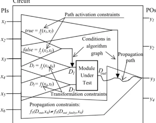
The high-level test generation constraints are divided into three categories. These are path activation constraints, transformation constraints and propagation constraints. Path activation constraints
correspond to the logic conditions in the control flow graph that have to be satisfied in order to perform propagation and value justification through the circuit. Transformation constraints, in turn, reflect the value changes along the paths from the inputs of the high- level Module Under Test (MUT) to the primary inputs of the whole circuit. These constraints are needed in order to derive the local test patterns for the module under test. Propagation constraints show how the value propagated from the output of the MUT to a primary output is depending on the values of the signals in the system. The main idea here is to guarantee that fault signals will not be masked when propagated.
All the above categories of constraints are represented by common data structures and manipulated by common procedures for creation, update, modeling and simulation.
Module Under Test Circuit
Propagation path
PIs POs
Path activation constraints
Transformation constraints Conditions in
algorithm graph false = f(x2,x3)
true = f(x1,x2)
D1 = f(x3,x4)
D2 = f(x4,x5) D 1
D 2 x 1
x 2
x 3
x 4
x 5
y 1
y 2
y 3
y 4 x 6 Propagation constraints:
f5(Dout,x6)≠ f5(Dout_faulty,x6) D out
1
2
3
4
Let us explain the role of these constraints in test generation on an example test path activation for a circuit module shown in Figure 2. In the Figure there are two path activation constraints: true = f1(x1,x2) and false = f2(x2,x3). The first one is necessary to propagate the value from the output of the module to the primary output y3 of the circuit. The latter is required for justification of the first input (D1) of the module under test. Both these constraints are extracted from the conditional nodes traversed in the control flow graph of the circuit during high-level path activation. The figure also presents two transformation constraints. These constraints are applied for computing the value of the corresponding module input depending on the values of primary inputs of the circuit. Finally, there is a propagation constraint, which states that the value propagated from the module to the primary output y3 is dependent on the primary input x6. Thus, in order to avoid fault masking the value of x6 must be chosen such that the fault free and faulty values of Dout would differ. Note, that the
Figure 2. Test generation constraints in DECIDER
subsets of the primary input variables included into the different types of constraints may overlap.
Table 1. Characteristics of the benchmark circuits circuit
# faults
# FSM states PI bits
PO bits
# of reg.
# of mux
# of FU
gcd16 1754 8 33 16 3 4 3
mult8x8 2036 8 17 16 7 4 9
ellipf 5388 28 130 113 17 7 3
risc 6434 4 26 16 8 4 4
diffeq 10,008 6 81 48 7 9 5
Table 2. Comparison of sequential circuit test generation tools
circuit HITEC GATEST DECIDER
F.C., % time, s F.C., % time, s F.C., % time, s gcd16 59.11 365 86.13 190.7 90.95 677.4 mult8x8 65.9 1243 69.2 821.6 74.7 93.7
ellipf 87.9 2090 94.7 6229 95.04 1258.9
risc 52.8 49,020 96.0 2459 96.5 150.5
diffeq 96.2 13,320 96.40 3000 97.09 453.7
aver. F.C.: 72.4 88.4 90.9
In our previous works we have proven the DECIDER to be an efficient tool for RTL circuits TPG. Table 1 [19] presents the characteristics of the example circuits used in test pattern generation experiments in this paper. The following benchmarks were included to the test experiment: a Greatest Common Divisor (GCD), an 8-bit multiplier (MULT8x8), an Elliptic Filter (ELLIPF), an ALU based processor (RISC) and a Differential Equation (DIFFEQ). The VHDL versions of GCD and DIFFEQ were obtained from high-level synthesis benchmark suites [16],[17] and the designs of MULT8x8 and RISC from functional test generation (FUTEG) benchmarks [18]. The second column „# faults“ shows the number of single stuck-at faults in the circuits, the third column „# FSM states“ shows the number of states in the control part FSM, and the columns „PI bits“ and „PO bits“ present the number of primary input and primary output bits, respectively. Finally, the 6th, 7th and 8th columns show the number of registers, multiplexers and functional units respectively.
In Table 2 [19], comparison of test generation results of three sequential ATPG tools on the hierarchical benchmark designs are presented. These include a gate-level deterministic ATPG HITEC [7], a genetic algorithm based GATEST [8], and DECIDER [19]. Columns „F.C., %“ give the single stuck-at fault coverages of the test patterns generated measured by the fault simulator from TURBO TESTER system [15], created at Tallinn University of Technology. Columns „time, s“ stand for test generation run-times achieved on a 366 MHz SUN UltraSPARC 60 server with 512 MB RAM under SOLARIS 2.8 operating system. The results show that DECIDER is very efficient for testing sequential designs. It achieves in
average 2.5 % higher fault coverage than the genetic tool GATEST on the given benchmark set.
3. Test generation for FSMs using
assertions
DECIDER relies on HLDD representations [19] of the design under test in order to generate the test patterns. The tool is capable of modeling FSMs, however, it is unable to target nodes in the FSM itself. This is due to the fact that the concept of testing FSMs is very different from datapath testing. When targeting datapaths, then the steps of fault manifestation, fault effect propagation and value justification are performed. Values are propagated through the datapath and FSM is taken into account only to keep track of the control state sequence.
However, when targeting FSMs and control dominated circuits then the approach differs. Here we need to:
Step A: activate a state sequence to the control state (or state transition) under test.
Step B: differentiate the fault-free and faulty control states (or state transition).
Step C: activate a sequence propagating this difference to observable outputs.
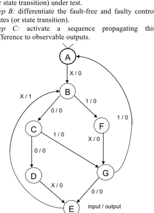
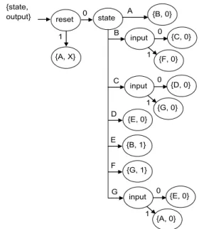
Consider the following motivational example based on the ITC99 benchmark circuit b02 [20] presented in Figure 3 shows the state diagram of the circuit and in Figure 4 its corresponding high-level decision diagram (HLDD) is given. The circuit has one input signal called input, one output signal called output, and one internal variable state. In the state diagram, the diagram nodes are labeled by FSM states {A, B, C, D, E, F, G} the edges are labeled by the
!
A
B
C F
D G
E
1 / 0
! X / 0 0 / 0 !
!
0 / 0
!
1 / 0
!
X / 0
!
0 / 0
! X / 1
!
X / 0
!
input / output
! 1 / 0
!
Figure 3. The FSM of the case-study circuit b02
values of inputs, which activate the corresponding transition and the output values at that transition. The input and output values are separated by a slash symbol. In the HLDD presented in Figure 4 the non- terminal nodes are labeled by inputs and current state and the terminal nodes are labeled by output and next state values, respectively. The HLDD computes values to a vector of design variables {state, output} during each clock cycle.
The fault models targeted during the test generation process by DECIDER for both FSM and datapath are expressed [19] using HLDDs.
Consider an incomplete set of verification assertions written in PSL language:
p1: assert always ({(state=A); [*3]; !input; }|=>{ output }); p2: assert always (input and !(state=D) -> next !output);
These two assertions represent checks for functional correctness of the FSM implementing the b02 design. The first assertion p1 states that if we have the following sequence of signal values: first we are in state A, and then after a three don’t-care clock cycles we have input set to zero then on the next clock cycle (|=> is a non-overlapping implication operator) the output will be set to 1. The second assertion p2 is interpreted as follows. If input is one and we are not in state D then at the next clock cycle output must be zero.
In a real design flow the verification engineer writes a longer set of assertions that represents properties specifying the behavior of the circuit. Such information, although created for verification purposes, could be used by the automated test generation algorithm because it contains some high-level knowledge about the functionality of the design.
For example, property p1 can be beneficial in activating the test sequence for value justification (step A of the FSM test generation, mentioned above). Assume that we need to justify state E, which is the only state where output is one, by backtracing a state sequence to the initial state A (See Figure 3). The information that is transferred to the ATPG by p1 is that when we justify, it is necessary to set input to zero after a three arbitrary values to reach E from A. Therefore, the justification sequence is easily derived just by moving to A, holding input equal to zero and waiting for 4 clock-cycles. Unnecessary backtracks and entering of loops during the systematic search will be avoided.
Similarly, the same assertion could be applied in propagation to state E from an arbitrary state of the FSM (Step C of FSM test generation).
Property p2 may be utilized in distinguishing the fault-free and faulty control states (Step B). For example, if we are in state D then we need to set input to one in order to distinguish it from other states.
In a similar manner the information from verification assertions can be reused for datapath TPG. Generally assertions consist of two parts: precondition and implication separated by the one of the implication operators (e.g. ->). Let’s denote the set of signals in the precondition part by SPand the set of signals in the implication part by SP.
Let’s consider a circuit under test containing two modules (Figure 5). And an abstract assertion W which both SP and SI are some of the signals crossed by the curved line in Figure 5.
W: fPrecondition (SP) -> fImplication (SI);
Then for a fault F1 in Module 1 both SP and SI can be used as a monitoring constraint, which allows to reduce the propagation time (Figure 6a) required for
Figure 6. Assertion applicability for TPG a)fault propagation b) fault justification.
a) b)
Module 1
F1
justification propagation
!
Module 2
F2
justification propagation
!
Figure 5. A circuit under test with two modules Module 1
Module 2 F2
F1
Circuit under test
Primary inputs Primary outputs
w Figure 4. The HLDD for the case-study circuit b02
! {state, output}
!
reset
! {A, X}
!
state
!
{B, 0}
! 0
1 !
!
A B !
!
input
!
{C, 0} {F, 0} !
! input
! 0 1 !
!
{B, 1}
! E
!
{E, 0}
! D
! C
! input
!
{D, 0} {G, 0} !
! input
! 0 1 !
!
{G, 1}
! F
! G
!
input
!
{E, 0} {A, 0} ! input
! 0 1 !
!
Step C. In case of a fault F2 in Module 2 the signals set SP can be controlled depending on the monitoring results of SI and thus can be used to reduce the justification time (Figure 6b) required for Step A.
The knowledge from assertions may be forwarded to the ATPG algorithm in the form of implications, similar to combinational gate-level ATPG algorithms taking advantage of implications and learning [22],[23],[24]. In order to allow the transfer of knowledge from verification assertions into the ATPG algorithm, both, representation of assertions and derivation of implications from them have to be formalized.
In Section 2 we have discussed constraints for test generation that are derived automatically from the circuit structure. An approach for the assertion information for TPG formalization can be their use to provide for additional constraints. The constraints from assertions allow avoiding unnecessary backtracks and thus can speed-up test generation process and increase the fault coverage.
4. Conclusions and future work
The paper has proposed an approach for design functional verification assertions reuse for manufacturing test pattern generation at Register- Transfer Level (RTL) for non-scan designs. The proposed assertions reuse allows our previously proposed constraint-based automated test pattern generator to increase fault coverage and speed-up test generation process. The discussed case-study demonstrates the feasibility and effectiveness of the proposed idea.
Acknowledgements
This work has been supported in part by Estonian Science Foundation through grants 8478 and 7068, by European Commission projects FP7-2009-IST-4- 248613 DIAMOND and FP7-REGPOT-2008-1 CREDES, by Research Centre CEBE funded by EU Structural Funds.
References
[1] J. Raik, R. Ubar, "Fast test pattern generation for sequential circuits using decision diagram representations", JETTA, Kluwer, 16(3), 2000.
[2] T. Viilukas, J. Raik, M. Jenihhin, R. Ubar, A. Krivenko, “Constraint-based Test Pattern Generation at the Register-Transfer Level”, Proc. of IEEE International Symposium on Design and Diagnostics of Electronic Circuits and Systems (DDECS’10), 2010
[3] H.D.Foster, A.C.Krolnik, “Creating Assertion-Based IP”, Springer, New York, 2008
[4] IEEE-Commission, IEEE standard for Property Specification Language (PSL), IEEE Std 1850-2005/2010, April 6, 2010
[5] IEEE Computer Society, IEEE standard for SystemVerilog-Unified Hardware Design, Specification, and Verification Language, IEEE Std 1800-2005/2009, December 11, 2009
[6] M. Jenihhin, J. Raik, R. Ubar, A. Chepurov, “On reusability of verification assertions for testing”, Proc. of IEEE Biennial Baltic Electronics Conference (BEC’08), Tallinn, Estonia, October 2008, pp. 151-154
[7] T. M. Niermann, J. H. Patel, "HITEC: A test generation package for sequential circuits", Proc. of European Conf. Design Automation (EDAC), pp.214-218, 1991.
[8] E. M. Rudnick, et al. "Sequential circuit test generation in a genetic algorithm framework", Proc. of DAC, pp. 698-704, 1994.
[9] D. Brahme, J. A. Abraham, "Functional Testing of Micro-processors", IEEE Trans. Comput., vol. C-33, 1984. [10] B. T. Murray, J. P. Hayes, "Hierarchical test generation using precomputed tests for modules", Proc. ITC, pp.221-229, 1988.
[11] H. Fujiwara, C. Y. Ooi, Y. Shimizu, "Enhancement of Test Environment Generation for Assignment Decision Diagrams", WRTLT, 2008
[12] M. R. Kakoee, M. Riazati, S. Mohammadi,
“Enhancing the Testability of RTL Designs Using Efficiently Synthesized Assertions”, Proc. of ISQED 2008, pp.230 - 235
[13] M. Boule, J.-S. Chenard, Z. Zilic, “Assertion Checkers in Verification, Silicon Debug and In-Field Diagnosis”, Proc. of ISQED 2007, pp. 613 – 620
[14] ECLiPSe Constraint Programming System, URL: http://eclipseclp.org/
[15] Turbo Tester Tools. URL: http://www.pld.ttu.ee/tt
[16] HLSynth92 benchmarks.
http://www.cbl.ncsu.edu/pub/Benchmark_dirs/HLSynth92/
[17] HLSynth95 benchmarks.
http://www.cbl.ncsu.edu/pub/Benchmark_dirs/HLSynth95/ [18] E. Gramatova, M. Gulbins, M. Marzouki, A. Pataricza, R. Sheinauskas, R. Ubar, “FUTEG Benchmarks,” Technical Report of project COPERNICUS JEP 9624 FUTEG No9/1995.
[19] Jaan Raik, Raimund Ubar, Taavi Viilukas, Maksim Jenihhin. Mixed Hierarchical-Functional Fault Models for Targeting Sequential Cores. Elsevier Journal of Systems Architecture, Vol. 54, Issue 3-4, pp. 465-477, Elsevier, March-April 2008.
[20] F.Corno, M.S.Reorda, G.Squillero, “RT-level ITC'99 benchmarks and first ATPG results”, Journal, Design & Test of Computers, IEEE, 17(3), July - Sept. 2000, pp. 44 – 53 [21] Pomeranz, I. and Reddy, S. M., Application of Homing Sequences to Synchronous Sequential Circuit Testing. IEEE Trans. Comput., vol. 43, number 5, pp. 569- 580, 1994.
[22] Paul Tafertshofer , Andreas Ganz , Manfred Henftling, A SAT-Based Implication Engine for Efficient
ATPG, Equivalence Checking, and Optimization of Netlists. Int. Conf. CAD, 1997.
[23] R. Mukherjee, J. Jain, M. Fujita, J. A. Abraham, D. S. Fussell, "On More Efficient Combinational ATPG Using Functional Learning," vlsid, pp.107, 9th International Conference on VLSI Design: VLSI in Mobile Communication, 1996.
[24] Bommu, S. Chandrasekar, K. Kundu, R. Sengupta, S., CONCAT: CONflict Driven Learning in ATPG for Industrial designs. International Test Conference, 2008.