Efficient Constraint Extraction for
Template-Based Processor Self-Test Generation
Kazuko Kambe
†Tsuyoshi Iwagaki
‡Michiko Inoue
†Hideo Fujiwara
††
Graduate School of Information Science, Nara Institute of Science and Technology
Kansai Science City 630-0192, Japan
‡
School of Information Science, Japan Advanced Institute of Science and Technology
1-1 Asahidai, Nomi, Ishikawa 923-1292, Japan
E-mail:
†{kazuk-ka, kounoe, fujiwara}@is.naist.jp,
‡[email protected]
Abstract
This paper presents efficient method to extract con- straints from a test program template and synthesize a test program using constraint circuits. A test program template is an instruction sequence with unspecified operands, and represents paths for justification of test patterns and obser- vation of test responses for a module under test (MUT). The constraint circuit represents a relation between operand values and inputs/output of the MUT, therefore it enables to obtain operand values using a standard automatic test pattern generator. Experimental results show that the pro- posed method generates accurate and compact constraint circuits, and we obtain high fault efficiency.
1. Introduction
Recent processor designs with giga-hertz speed and rich functionality demand for accurate and at-speed testing. Software-based self-test attracts attention as a testing strat- egy enabling at-speed test [1, 2, 3, 4, 5, 6, 7]. In this ap- proach, a processor enables self-test by running a sequence of instructions called a test program. Therefore, it does not induce any performance penalty, area overhead or ex- cessive power. Recent works are towards hierarchical test generation approach targeting structural faults where gate level tests for modules in processors are linked with test programs at processor level. In this approach, values or se- quences of values applicable to the modules inside the pro- cessor are restricted as a test program delivers test patterns to the modules. These works extract such restrictions for a module under test (MUT) as constraints, then apply an au- tomatic test pattern generator (ATPG) to the MUT with the extracted constraints. Finally, the generated tests are trans- formed into test programs.
The method in [8] reduces a target circuit to a subset of the circuit surrounding an MUT by analyzing RTL descrip- tions and applies ATPG to the subset circuit. However, the
generated test patterns might induce overtesting at instruc- tion level, since the method does not consider constraints imposed instructions. Furthermore, it is possible that the extracted subset is the same size as the original design in the worst case.
The methods in [5], [6] and [7] are proposing test pro- gram generation based on test program templates (or just templates) targeting stuck-at faults. A template is an in- struction sequence with unspecified operands that delivers tests to an MUT and observes the test responses. The meth- ods extract constraints from each template since the tem- plate represents ways to propagate tests from primary in- puts and the test response to primary outputs. Therefore, the generated tests for a module are guaranteed to be trans- formed into test programs. However, in [5], constraints are obtained by a regressive analysis for randomly generated values of operands, and it might be difficult to find accu- rate constraints if mapping functions between operands and MUT inputs are complicated.
In this paper, we present an efficient method to extract constraints from a template that generated by our previous method in [6]. Our technique analyzes RTL descriptions of a processor according to behavior of a template and synthe- sizes constraint circuits, which work as mapping functions between operands and MUT inputs. We obtain operand val- ues from generated test patterns using standard ATPG. The method has the following advantages: (i) we can generate an accurate and compact constraint circuits even if a rela- tion between operands and MUT inputs is complicated, (ii) a constraint circuit is synthesized as a combinational circuit by applying time expansion to a template, thereby we apply combinational ATPG to a combinational MUT.
This paper is organized as follows. In Sections 2 and 3, we give a brief explanation of our self testing system and template generation method in [6]. A method of constraint extraction is proposed in Section 4, and the experimental results are shown in Section 5. Finally, Section 6 concludes this paper.
1
IEEE the 14th Asian Test Symposium (ATS'05), pp. 444-447, Dec. 2005.
Yes No
No Yes
applying ATPG template generation
constraint circuit synthesis
fault simulation by test program test program synthesis cotrollability/observability analysis
no more template? redundant fault identification
acceptable FC?
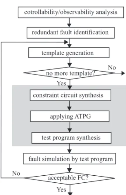
Figure 1. Overview of test program genera- tion.
2. Template based test program generation In our methodology, constraints are extracted by tem- plates. A template is a sequence of instructions with un- specified operands, and represents paths for justification of test patterns and observation of test responses for an MUT.
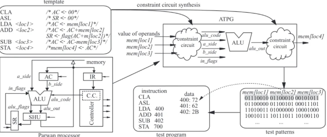
Example 1 An example in Figure 2 is a template for test- ing Arithmetic Logic Unit (ALU ) of Parwan processor [9], where loc1, loc2, loc3 and loc4 are operands of instruc- tions. The values are unspecified. First four instructions, CLA, ASL, LDA and ADD, justify values of Status Reg- ister (SR) and Accumulator (AC). Next SUB applies test patterns to ALU . STA observes the test response stored in
AC. ✷
We explain an overview of our test program generation in Figure 1. We first analyze controllability and observabil- ity of registers to use for instruction selection. We identify redundant faults prior to test program generation. Here, we consider a fault is redundant if no test program detects the faults. The method in [7] proposed to identify redundant faults for sequential modules. Control signals applicable to combinational modules from a controller are restricted to constant values imposed by instruction code. We apply such restriction to the MUT as constraints. For each MUT, we re- peat the following. We generate a template, and synthesize input/output constraints of the MUT from the template. Af- ter applying ATPG, a test program is transformed from the test patterns. In the next step, a fault simulation is applied to an entire processor. We generate multiple templates to cover input space for MUTs. These processes are repeated until all templates are generated or fault coverage reaches the re-
quired level. A methodology for template generation was described in [6]. In this paper, we focus the steps from con- straint circuit synthesis to test program synthesis in shaded area of the figure.
3. Template generation
In our template generation method, we first select in- structions to justify values of each input adjacent registers. Input/output adjacent registers of an MUT are defined as registers that are connected with inputs/outputs of the MUT directly or indirectly through combinational circuits. Once values of input adjacent registers are justified, the test pat- terns can be applied to inputs of the MUT. If some registers still require justification, more instructions should be se- lected until source registers of instructions reach the mem- ory. We also select instructions to propagate the fault effect to the memory such that the instructions observe a value of an output adjacent register, and append to the end of the template. Since one template may not cover the whole in- put space of an MUT, we generate more templates. Our method uses an IE-Graph proposed in [4] to explore deliv- ering routes for justification and propagation. An IE-Graph is a model of data flow between registers. Nodes are reg- isters, IN and OUT, which model external world such as the memory. A directed edge between two nodes represents data transfer between registers controlled by an instruction. More details regarding template generation method can be found in [6].
4. Constraint extraction
Figure 2 illustrates an outline of test program gener- ation for a template. The ALU has four inputs (a side, b side, alu code and in f lags) and two outputs (alu out and alu f lags). We synthesize input/output constraints from the template. The circuits describe relations between values of operands (mem[loc1], mem[loc2], mem[loc3] and mem[loc4]) and inputs/output of ALU in HDL coding style. We apply ATPG to a circuit that consists of input/output constraint circuits and the MUT, targeting faults in the MUT. Now, generated test patterns are directly linked to the operand values. In consequence, it is easy to synthesize a test program.
Time expansion of template
We are interested in relations between values of operands and inputs/output of an MUT. In our method, we perform time expansion of a template, and eliminate registers. We represent necessary data flow for justification/observation paths as a sequence of module instances where modules have different instances for different time frames. We can naturally obtain such data flow during traversing paths in an IE-graph to select instructions for template generation. We construct an instance data flow graph (IDFG) to repre- sent data flow between module instances. Figure 3 shows an example of a partial IDFG. It corresponds to a part of
2
CLA /* AC <- 00*/ ASL /* SR <- 00*/ LDA <loc1> /*AC <- mem[loc1]*/ ADD <loc2> /*AC <- AC+mem[loc2]
SR <- flag(AC+m[loc2])*/ SUB <loc3> /*AC <- AC-mem[loc3]*/
STA <loc4> /*mem[loc4] <- AC*/ ALU
constraint circuit synthesis
value of operands mem[loc1] mem[loc2] mem[loc3]
alu_out a_side
b_side alu_code
in_flags ATPG
constraint
circuit constraintcircuit
template
instruction CLA ASL LDA 400 ADD 401 SUB 402 STA 700
data 400: 72 401: 62 402: 2B
test program
mem[loc4]
01110010 01100010 00101011 01100000 01100101 00011101 11010011 01000000 10001000 10010111 10111011 10100110 ... ... ... mem[loc1] mem[loc2] mem[loc3]
test patterns ALU
AC
SHU
SR
b_side a_side
alu_out alu_flags
memory
alu_code
Controller
IR in_flags
C.C.
Parwan processor
Figure 2. Test program generation.
execution of an instruction sequence: ADD, SUB and STA. Nodes of an IDFG are instances of modules, IN or OUT. Each node is marked with a [state, instruction] pair, which means that data transfer occurs at the state of a controller during executing the instruction where an execution of the instruction consists of multiple cycles. Each module in- stance has a RTL description duplicated from the descrip- tion of the module. A directed edge between represents data flow between nodes. Each edge is labeled with a set of [source signal name, destination signal name] pairs. The signal names are described in RTL descriptions. This in- formation of labels is used to simplify RTL descriptions of modules.
Optimization and synthesis of constraint circuits When a module is instantiated to a specified state of con- troller during the execution of an instruction, all of the paths in modules are not activated. Therefore, extracting mean- ingful functions of modules regarding a specified instruc- tion enables to reduce RTL descriptions. We will describe how to optimize RTL descriptions.
In a RTL description of module behavior, conditional branch statements are generally used to specify a set of statements to execute based on value of given selection sig- nal. Such signals might be given from a controller. Ana- lyzing behavioral descriptions of a controller, we can find that control signals have constant values corresponding to
SHUsta
INsub
SRadd
ALUsub
ACadd
SHUsub ACsub
ALUsta
OUTsta
IRsub
INsub
[S6, ADD]
[S2, SUB] [S2, SUB] CTRLsub [S6, SUB] [S6, SUB]
[S6, SUB] [S6, SUB]
[S6, STA] [S6, STA]
[S6, STA] [alu_out, alu_side]
[S6, ADD] RTL description
Figure 3. Instance data flow graph.
each state during executing an instruction. The following fragment of VHDL code is a RTL description of ALU in Parwan processor.
case alu_code is when a_input =>
t := "00" & a_side;
c := in_flags(2); v := in_flags(3); when ...
......
when others => t := "0000000000"; c := ’0’; v := ’0’; end case;
When the processor executes LDA, a signal value alu codeis ”a input” for a state, and 3rd and 4th lines are executed. Other statements are unnecessary. Consequently, we easily extract functions of modules which are instan- tiated during executing an instruction, and eliminate dead codes and unnecessary ports once values of signals are spec- ified to constant values.
Now, we synthesize constraint circuits in HDL code from an IDFG. We first apply topological sort to nodes of the IDFG, in order to divide into two parts, justification and observation. After applying topological sort, the to- tal ordered node sequence is obtained. For each module instance in the ordered sequence, we generate behavioral descriptions by optimizing in ways described above. We also describe structures in HDL codes for input/output con- straint circuits, where module instances are connected to- gether with signals according to data flow dependence.
For sequential modules, an input temporal spatial con- straintwas introduced in [7]. An input temporal spatial con- straint of a module is a sequence of input constraints. We extract a constraint for each cycle from the first cycle of the instruction that applies test patterns to an MUT, to the in- struction fetch cycle of the next instruction in a template. An input constraint circuit for a sequential MUT consists of a simple sequencer and some combinational constraint circuits where a combinational constraint circuit represents
3
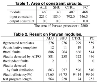
Table 1. Area of constraint circuits.
ALU SHU CTRL PC
module 460 140 407 468
input constraint 221.0 185.0 792.0 746.5
output constraint 0.0 0.0 - 0.0
The area of Parwan processor : 2800 Table 2. Result on Parwan modules.
ALU SHU CTRL PC
#generated templates 276 276 299 559
#contributive templates 12 11 19 3
#total faults 886 264 666 544
#faults detected by ATPG 881 258 622 436
#redundant faults 2 1 29 0
#faults detected
by fault similation 863 257 596 540
#fault efficiency(%) 97.63 97.73 94.14 99.26
test program length 564 228 74 253
a constraint for a cycle and the sequencer selects the con- straint corresponding to the cycle.
5. Experimental results
Extracting meaningful functions of module instances yields dead codes and unnecessary ports. In this paper, we eliminated such dead codes and ports, and synthesized con- straint circuits by a logic synthesis tool Design Compiler from Synopsys.
We evaluated the proposed method for Parwan proces- sor. Table 1 shows the average of constraint circuit area for modules. The area of output constraint circuits for ALU , Shifter Unit(SHU ) and Program Counter(PC) are 0.0, how- ever, the circuits have some lines. This shows that the value of MUT outputs can be observed at primary outputs as it is. In this experiment, we assume a fault to be detectable if an error is propagated to the outside of a controller; ac- cordingly, output constraint circuits for Controller(CT RL) were not synthesized. Notice that every constraint circuit is small. The input constraint circuits of CT RL and PC which are sequential modules are more than 1.5 times of the mod- ules. However, the average of constraint circuit area per cycle is 126.2 for CT RL, and 98.2 for PC, respectively. The constraint circuits for sequential modules are also compact. We combined constraint circuits with an MUT, and ap- plied ATPG tool TestGen from Synopsys to the circuit. The results are shown in Table 2. Row 2 is the total number of generated templates, and row 3 is the number of tem- plates that actually contributed to detecting faults. Other rows show total faults of each module, the number of faults detected by ATPG. Test programs detected faults in row 7. Consequently, we can achieve high fault efficiency for ev- ery module. The experimental results show that our method can synthesize accurate and compact constraint circuits ef- ficiently.
6. Conclusion
This paper presented an efficient constraint extraction method based on templates. We proposed systematic method to extract constraints and synthesize test programs using constraint circuits. The constraint circuit represents relations between values of operands and inputs/output of the MUT. The experimental results showed that we could generate an accurate and compact constraint circuit. Hence, we can perform test generation and test program synthesis efficiently. We obtained high fault efficiency for each mod- ule.
Acknowledgments We would like to thank Prof. Satoshi Ohtake, Prof. Tomokazu Yoneda, Mr. Virendra Singh and everyone in Computer Design and Test Lab. of Nara In- stitute of Science and Technology for their valuable com- ments. This work was supported in part by Semiconductor Technology Academic Research Center (STARC) under the Research Project and in part by Japan Society for the Pro- motion of Science (JSPS) under Grants-in-Aid for Scientific Research B(2)(No. 15300018).
References
[1] S. M. Thatte and J. A. Abraham, !HTest generation for mi- croprocessors,!IIEEE Trans. on Computers, Vol. C-29, No.6, pp. 429–44, 1981.
[2] K. Batcher and C. Papachristou,!HInstruction randomization self test for processor cores, !IProc.17th VLSI Test Symp., pp. 34–40, 1999.
[3] W.-C. Lai, A. Krstic and K.-T. Cheng,!HTest program syn- thesis for path delay faults in microprocessor cores, !IProc. Int. Test Conf., pp. 1080–1089, 2000.
[4] V. Singh, K. K. Saluja, M. Inoue and H. Fujiwara,!HDelay fault testing of processor cores in functional mode, !IIEICE Trans. on Information and Systems, Vol. E88-D, No.3, pp. 610–618, 2005.
[5] L. Chen, S. Ravi, A. Raghunathan and S. Dey,!HA scalable software-based self-test methodology for programmable pro- cessors, !IProc. 40th ACM/IEEE Design Automation Conf., pp. 548–553, 2003.
[6] K. Kambe, M. Inoue and H. Fujiwara, !HEfficient template teneration for instruction-based self-test of processor cores,!I Proc. 13th Asian Test Symp., pp. 152–157, 2004.
[7] M. Inoue, K. Kambe, N. Hoashi and H. Fujiwara,
!HInstruction-based self-test for sequeintial modules in pro- cessors,!IIEEE 5th Workshop on RTL and High Level Testing (WRTLT’04), pp. 109–114, 2004.
[8] M. Vedula, J. A. Abraham, J. Bhadra and R. S. Tupuri,!HA hierarchical test generation approach using program slicing techniques on hardware description languages!I, J. Electronic Testing: Theory and Applications, Vol. 19, No. 2, pp. 149– 160, 2003.
[9] Z. Navabi, VHDL analysis and modeling of digital systems, McGraw-Hill, New York, 1997.
4