An Extended Class of Acyclically Testable Circuits
Nobuya Oka
†, Chia Yee Ooi
‡, Hideyuki Ichihara
†, Tomoo Inoue
†, and Hideo Fujiwara
∗†Graduate School of Information Sciences, Hiroshima City University 3-4-1, Ozuka-higashi, Asaminami-ku, Hiroshima, 731-3194 Japan
‡Faculty of Electrical Engineering, Universiti Teknologi Malaysia, 81310 UTM Skudai Johor MALAYSIA
∗Graduate School of Information Science, Nara Institute of Science and Technology, Kansai Science City 630-0192. Japan [email protected],{ichihara, tomoo}@hiroshima-cu.ac.jp, [email protected], [email protected]
Abstract
The class of acyclically testable sequential circuits [7] in- cludes that of acyclic sequential circuits, and furthermore these classes are equivalent in test generation complexity. In this work, we consider an extension of the class of acyclically testable sequential circuits. To extend the class, we introduce a pair of justification and propagation thru trees, instead of the thru trees presented in [7]. Based on the thru tree pair, we propose an extended class of acyclically testable sequential circuits. While the new class properly includes the previous class, it is conjectured that the test generation complexity of the new class is equivalent to that of the previous one. Ex- perimental results show that the DFT method based on the proposed class requires smaller overhead than the previous one with smaller test generation time.
Key words : test generation, acyclic testability, design- for-testability, combinational test generation complexity,τk notation.
1 Introduction
The test generation problem even for combinational cir- cuits, was shown to be NP-complete [1], but empirical observations tell us that the test generation complexity of practically encountered combinational circuits seems to be polynomial[2]. On the other hand, the problem of test gen- eration for sequential circuits is hard to be solved in prac- ticable time. In many cases, the problem is converted into that for combinational circuits by full scan design. How- ever, there exist some sequential circuits whose test gener- ation is practically tractable as well as the test generation complexity of combinational circuits. Ooi et al. introduced that any sequential circuits can be classified by denoting τ =Θ(nr) (n is the size of the combinational circuit, r is some constant larger than 2) as the test generation complex- ity of combinational circuits[3, 4]. For example, the test gen- eration complexity for the sequential circuits that have bal- anced structure or internally balanced structure is said to be τ-equivalent because it is equivalent to combinational test generation complexity[5, 6]. The test generation complex- ity of general acyclic sequential circuits is denoted by τ2- bounded (O(τ2(n))). This means general acyclic sequen- tial circuits are comparatively easily testable though they are more hardly testable than combinational circuits and the se- quential circuits with balanced structure and internally bal- anced structure. In addition, the authors introduced a wider
R2
CLB4
CLB5 CLB2 R1
R3
R4
R5 PI1
t
1 ●PI2 0
X 1 X 2 X
4 X 5 C' 3 X
0 A 1 X 2 X
4 X 5 X 3 D
0 X 1 X 2 B
4 X 5 X 3 X
t
2t
3PI3
PO1
PI4 CLB1
CLB3
Figure 1. Sequential circuit S1
class called acyclically testable sequential circuits whose test generation complexity isτ2-bounded. Note that this class is wider than the class of acyclic sequential circuits but its test generation complexity is equivalent to that of the acyclic se- quential circuits [7]. They defined a thru tree whose its root is a primary output, its leaves are primary inputs and each of its edges represents a thru function. A sufficient condition of acyclical testability were defined based on the thru trees.
In this work, we discuss an extension of the class of acyclically testable sequential circuits. We propose a pair of justification and propagation thru trees instead of the thru trees presented in [7]. Based on the thru tree pair, we in- troduce a new class of sequential circuits named extended acyclically testable sequential circuits. The class of extended acyclically testable sequential circuits properly includes that of acyclically testable sequential circuits. This implies that the DFT based on the extended acyclical testability requires smaller hardware overhead than the DFT based on the acycli- cal testability. Experimental results show that the DFT over- head based on the extended acyclical testability is smaller than that based on the previous class, while complete fault efficiency can be obtained.
2 Acyclically testable circuits
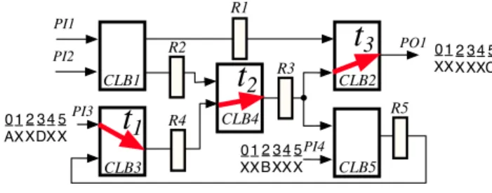
2.1 R-graph for sequential circuitsAn example sequential circuit considered in this work is illustrated in Fig. 1. A sequential circuit is composed of com- binational logic blocks(CLBs), registers and connections be- tween CLBs and registers. Some CLBs have thru functions. Here we consider two types of thru functions as shown in Fig. 2. One is a simple thru: it transfers the data of an input of the CLB to the output independent of other inputs. The other is a merge thru: it binds the data of a certain number of inputs and transfers them to the output without modification. IEEE 8th Workshop on RTL and High Level Testing (WRTLT'07), pp. 17-22, October 2007.
d
CLB t1 am1
(a)simple thrufunction
(b)merge thru function m4=m1
c b m2
f
h g
m3 m5=m2e
d
CLB
m6 m9=m6+m7
m7
m8 m10e
t2
t3 t3
Figure 2. Thru function
PI2
PI3 R1
R2 R3
R4 PI4 R5
PO1
t
1t
3 PI1t
2Figure 3. R-graph of se- quential circuit S1
A sequential circuit is represented by an R-graph defined as follows.
Definition 1 (R-graph): An R-graph is a directed graph GR= (V, A, w, r,t) that has the following properties.
1. A vertex v(∈ V ) corresponds to a register, a primary in- put or a primary output. Sets VR, VIand VOare a set of registers, primary inputs and primary outputs, respec- tively. Then, the set V represents the union of VR, VI
and VO, i.e., V= VR∪VI∪VO.
2. An arc(u, v) (∈ A) denotes a connection via combina- tional logic blocks or directly from u corresponding to a register or a primary input to v corresponding to a reg- ister or a primary output.
3. The mapping w(v) (w : V → Z+) denotes the bit width of v corresponding to a register, a primary input or a primary output, where Z+denotes a set of non-negative integers.
4. The mapping r(v) (r : v → {h,φ}) defines the type of the vertex. If r(v) = h, v corresponds to a hold register. Otherwise if r(v) is empty, i.e., r(v) =φ, v corresponds to a register with no hold function, a primary input or a primary output.
5. For any arc (u, v), if (u, v) has a thru function ti, the mapping t(u, v) is denoted by t(u, v) = ti. If there exists no thru function for(u, v), t(u, v) is empty (t(u, v) =φ), i.e., t : V2→ F ∪ {φ}, where F = {t1,t2, ...,tm} denotes a set of thru functions.
For example, Fig. 3 shows an R-graph for sequential cir- cuit S1.
If a thru function ti is active according to the values of a subset V′of primary inputs and registers(i.e., V′⊆ VI∪VR), ti
is said to be activated by V′, and expressed asα(ti) = Vt(α: F → 2V). If α(ti) is empty (i.e., α(ti) =φ), ti is always activated.
2.2 The test generation complexity of acyclic se- quential circuits
In [3, 4], the test generation complexity of combinational circuits is denoted byτ(n) (=Θ(nr)) (n is the size of the combinational circuit, and r is some constant larger than 2), and that of a sequential circuit is expressed by means ofτk.
●
0 X 1 X 2 G 0
A 1 E 2 X 0 B 1 F 2 X 0 C 1 X 2 X 0 D 1 X 2 X
R2
CLB4
CLB5 CLB2 R1
R3
R4 PI1
PI2
PI3
PO1
PI4 CLB1
CLB3
PO2 PI4
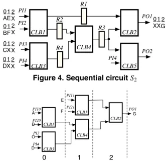
Figure 4. Sequential circuit S2
PO1
CLB3
PI3 CLB4
CLB1 PI10
PI20
0 1 2
A
B
C
CLB2 CLB1
PI11
PI21
PI4 D
E
F G
Figure 5. Time expansion model C(S2,CLB2) for CLB2 of S2
Based on this notation, the test generation complexity of acyclic sequential circuits is denoted by O(τ2(n)) (i.e.,τ2- bounded). This implies that the class of acyclic sequential circuits is comparatively easily testable. For example, con- sider an acyclic sequential circuit S2illustrated in Fig. 4. The test generation for S2can be performed on a time expansion model (TEM) as shown in Fig. 5. A TEM consists of CLBs and their connections, and represents the time when the out- put of each CLB is determined by other CLBs. Note that a TEM has no registers and thereby is a combinational circuit. When a test pattern (PI10, PI20, PI3, PI4, PI11, PI21
: PO1) = (A, B, C, D, E, F : G) is obtained from TEM C(S2,CLB2) for CLB2 of S2illustrated in Fig. 5, the corre- sponding test sequence for S2is (PI1, PI2, PI3, PI4, PI5 : PO1, PO2) =⟨ (A, B, C, D, X : X, X), (E, F, X, X, X : X, X), (X , X , X , X , X : G, X )⟩. Here, the length of a TEM refers to the number of time frames (i.e., the difference between the maximum and minimum numbers labeled for CLBs plus 1) in the CLB. For example, the length of TEM C(S2,CLB2) in Fig. 5 is 3.
2.3 Acyclical testability
The previous work [7] introduced a class of acyclically testablesequential circuits whose test complexity is equiva- lent to that of acyclic sequential circuits, i.e., the complexity isτ2-bounded. For example, sequential circuit S1in Fig. 1 is acyclically testable. R-graph of S1 is illustrated in Fig. 3. Note that the R-graph has a cycle consisting of vertices R3, R4 and R5, i.e., it is not acyclic. In this R-graph, any of vertices R3, R4 and R5 can compose a feedback vertex set (FVS)1. Sequential circuit S1has a path from primary input PI3 to primary output PO1, consisting only of simple thrus
1For a direction graph G= (V,A), a subset of the vertex set V′(⊆ V ) is a feedback vertex set if the subgraph of G induced by V−V′is acyclic.
CLB5
PI4 CLB3
PI31
CLB4
CLB2 PO1
CLB3 PI30
CLB4
0 1 2 3 4 5
A
B C
C'
A D
C'
t
1t
2t
3t
2Figure 6. Time expansion model C(S1,CLB5) for CLB5 of S1
t1, t2and t3. Accordingly, R3 and R4 can be justified from PI3, and can be observed at PO1. In other words, the path with thrus can be considered to be a scan path of R3 and R4, and consequently the test generation for S1can be achieved in the same way as acyclic sequential circuits. Such a thru path is referred to as a thru tree [7]. In [7], the sufficient con- ditions of acyclically testable is denoted with the concept of thru tree. One of the conditions is that an FVS is covered by the thru trees, e.g., in the R-graph in Fig. 3, the thru tree with thrus t1, t2and t3covers an FVS{R3}. If a sequential circuit satisfies the sufficient conditions, a TEM for any CLB in the sequential circuit can be constructed. For example, a TEM C(S1,CLB5) for CLB5 of S1is shown in Fig. 6.
3 Extended class of acyclically testable se-
quential circuits
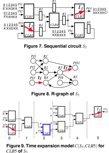
Let’s consider sequential circuit S3in Fig. 7. Note that, unlike sequential circuit S1 in Fig. 1, S3 has no thru func- tion in CLB4. Fig. 8 shows the R-graph for sequential circuit S3. As we can see from Fig. 8, S3 has no thru tree from PI3 to PO1. Accordingly it is not acyclically testable. How- ever, we can obtain a TEM for any CLB. A TEM for CLB5 C(S3,CLB5) is shown in Fig. 9.
For a given TEM, a test sequence generated for a fault in C(S, B) must correspond to a test sequence for the corresponding fault in S. A test pattern generated on C(S3,CLB5) can be transformed to a test sequence. When a test pattern(PI10,PI20,PI30,PI4, PI11,PI21,PI31: PO1) = (E, F, A′,B, G, H, D : C′′) is obtained on TEM C(S3,CLB4) for CLB5 of S3 illustrated in Fig. 9, the corresponding test sequence for S3 is (PI1, PI2, PI3, PI4 : PO1) = ⟨(E, F, A′,X : X), (X, X, X, B : X), (G, H, D, X : X), (X, X, X, X : X), (X, X, X, X : C′′)⟩.
This example implies that an FVS in an R-graph does not always need to be covered by thru trees whose root and leaves are a primary output and primary inputs, respectively. In the R-graph in Fig. 8, two FVSs R4 and R3 are covered by the two partial thru trees, one contains just thru functions t1and the other contains t3. Hence, any value of register R4 can be justified with thru function t1, and any value of reg- ister R3 can be propagated to primary output PO1 with thru function t3. Such justification and propagation are sufficient for testing CLBs.
In the following discussion, we present justification thru trees and propagation thru trees in place of the thru trees defined in [7], and propose an extended class of acyclically
●
0 X 1 X 2 X
4 X 5 C'' 3 X
0 X 1 X 2 B
4 X 5 X 3 X 0
A' 1 X 2 X
4 X 5 X 3 D 0 E' 1 X 2 X
4 X 5 X 3 G 0 F 1 X 2 X
4 X 5 X 3 H
t
1t
3R2
CLB4
CLB2 R1
R3
R4
R5 PI1
PI2
PI3
PO1
PI4 CLB1
CLB3 CLB5
Figure 7. Sequential circuit S3
PI2
PI3 R1
R2 R3
R4 PI4 R5
PO1
t
1t
3PI1
Figure 8. R-graph of S3
PI4
PI31
PO1
PI30 CLB1 PI10
CLB1 PI11
PI20
PI21
0 1 2 3 4 5
C'' E
F
A'
B G
H
A D
C
C'
C''
t
1t
3CLB5 CLB3
CLB4
CLB2
CLB3
CLB4
Figure 9. Time expansion model C(S3,CLB5) for CLB5 of S3
testable sequential circuits.
3.1 Thru trees for justification and propagation For any cycle, if there exists a thru path for justification to any register on the cycle and a thru path for propagation from any register on the cycle, a TEM for testing any CLB can be derived. Here, a pair of thru trees are defined as follows. Definition 2 (Justification thru tree and propagation thru tree): Let GR= (V, A, w, h,t) be an R-graph. A justification thru tree TJ= (VJ,AJ), (VJ⊆ V, AJ⊆ A) is a subgraph of GR
that satisfies the following conditions.
1. Any leaf v(∈ VJ) corresponds to a primary input, i.e., v∈ VPI.
2. Any arc(u, v) (∈ AJ) has a thru function, i.e., t(u, v) ̸= φ.
3. All inputs of a merge thru function are included in TJor no input is includes in TJ, i.e.,∀ti⊆ F, (t−1(ti) ∩ AJ= t−1(ti)) ∨ (t−1(ti) ∩ AJ=φ).
A propagation thru tree TP= (VP,AP), (VP⊆ V, AP⊆ A) is a subgraph of GRthat satisfies the following conditions.
1. The root v(∈ VP) corresponds to a primary output, i.e., v∈ VPO.
2. Any arc(u, v) (∈ AP) has a thru function , i.e., t(u, v) ̸= φ.
Definition 2 implies that any vertex (or a register) in a justification thru tree TJ can be justified from primary in- puts, and any vertex (or a register) in a propagation thru tree TP can be observed at a primary output. Note that justifi- cation and propagation with thru trees can be regarded as scan-in and scan-out operation, respectively. Therefore, if justification (resp. propagation) thru trees cover an FVS for an R-graph, we can justify (resp. observe) at least one regis- ter on every cycle in the sequential circuit corresponding to the R-graph.
In the R-graph of sequential circuit S3(Fig. 8), justifica- tion and propagation thru trees are TJ = (VJ = {PI1, R4}, AJ = {(PI1, R4)}) and TP = (VP = {R3, PO1}, AP = {(R3, PO1)}), respectively. Note that the FVS for the R- graph is corresponding to that for R-graph of S1. Vertices R4 and R3 are included in thru trees TJ and TP, respec- tively. Accordingly registers R3 and R4 in the FVS can be justified from primary input and the registers can be ob- served from a primary output. Based on this property, TEM C(S3,CLB5) for CLB5 of S3 can be obtained as shown in Fig. 9. Note that if arc(PI4, R5) has a thru function, the sub- graph ({PI4, R5}, {(PI4, R5)}) can be another justification tree, and hence a different TEM can be available.
When a justification thru tree is identical to a propaga- tion one, i.e., TJ= TP, the thru tree corresponds to the thru tree defined in [7]. Thus, a class of pairs of justification and propagation thru trees includes that of the thru trees defined in [7].
3.2 Extended acyclically testable sequential cir- cuits
A thru function for a sequential circuit is activated accord- ing to values in registers or primary inputs. These thru tree relationship is denoted as follows.
Definition 3 (Dependency between thru trees): Let Ti = (Vi,Ai) and Tj = (Vj,Aj) be thru trees of GR. Let thru tree Ti = (Vi,Ai), D(Ti) denote a set of registers or primary inputs that activate a thru function t (∈ Ti), i.e., D(Ti) = ∪a∈Aiα(t(a)). If there exists a vertex v that acti- vates a thru function t(∈ Ti), i.e., v ∈ D(Ti), Ti depends on vertex v. And, for two thru trees Tiand Tj, if the union of D(Ti) and Vjis not empty, i.e., D(Ti) ∩Vj̸=φ, Tidepends on Tjand this relation is represented as Ti≺ Tj.
For a sequential circuit with justification and propagation thru trees, if the sequential circuit has a dependency between thru trees, there is a possibility that thru functions cannot be activated in some TEMs.
Let us consider sequential circuit S3illustrated in Fig. 7. Suppose that thru function t1is activated by the value of PI2 (α(t1) = PI2), that is, the justification thru tree TJ= (VJ= {PI1, R4}, AJ= {(PI1, R4)}) depends on primary input PI2. Here, let us consider that registers R2 and R4 are justified simultaneously. Because ofα(t1) = PI2, primary input PI2 needs a particular value to justify R4 with thru function t1. On the other hand, to justify R2, another particular value may be needed on primary input PI2. Thus, these values on pri-
PI30 CLB1 PI10
PI20
1 2
t
1CLB3
CLB4
0
Figure 10. Time expansion model C(S3,CLB4) for CLB4 of S3
mary input PI2 may be conflict, and consequently some test patterns for CLB4 may not be justified.
Some dependencies of thru trees can be solved with a hold function of a register. For example, in S3shown in Fig. 7, if registers R2 or R4 have a hold function, input to CLB1 and activation for thru function t1can be implemented in separate time frames. As a result, TEM C(S3,CLB4) can be obtained as shown in Fig. 10. Whether the value confliction should be adjusted with hold functions depends on not only the de- pendency of thru trees but also the dependency of paths. The definition of path dependency is as follows.
Definition 4 (Dependency between paths): Let p= (u1,u2, ...,unp) and q = (v1,v2, ...,vnq) be paths in an R- graph. If the following conditions are satisfied, p depends on q.
1. The lengths of paths p and q are equal, i.e., np= nq(= n).
2. The end vertices on paths p and q are the same, i.e., unp= vnq.
3. The first arc (u1,u2) of paths p has a thru function, i.e., t(u1,u2) ̸=φ.
4. The start vertices on paths p and q are the same or the thru function of arc (u1,u2) is activated by vertex v1on q, i.e., v1∈α(t(u1,u2)).
Based on the above definitions, a sufficient conditions of extended acyclically testable sequential circuits is as follows. Definition 5 (a set of thru tree pair in sequential circuit):
For an R-graph GR = (V, A, w, r,t) of a sequential cir- cuit S, if S has a set of justification thru trees TTTJ = {TiJ= (ViJ,AJi), i = 1, 2, ..., nJ} and propagation thru trees TTTP = {TiP= (ViP,APi), i = 1, 2, ..., nP}, and hold registers such that satisfies the following conditions, S is said that S has a set of thru tree pair (TTTJ,TTTP). Here, TTT = TTTJ∪TTTP, VTJ= ∪ni=1J ViJ, VTP= ∪ni=1P ViP.
1. The set of justification thru trees TTTJsatisfies the follow- ing conditions.
(a) All thru trees in TTTJ are disjoint, i.e., ∀i, j(i ̸= j),ViJ∩VjJ=φ.
(b) A vertex set VTJincludes all vertices composing at least one FVS, i.e., for any FVS V′(⊆ V ), V′⊆ VTJ. (c) Any vertex v(∈ VTJ) corresponds to a hold register,
i.e.,∀v ∈ VTJ,r(v) = h.
2. The set of propagation thru trees TTTPsatisfies the follow- ing conditions.
(a) All thru trees in TTTP are disjoint i.e., ∀i, j(i ̸= j),ViP∩VjP=φ.
(b) Vertex set VTPincludes all the vertices composing at least one FVS, i.e., for any FVS, V′(⊆ V ), V′⊆ VTP.
(c) For any vertex v(∈ VTP), v corresponds to a hold register, i.e.,∀v ∈ VTP,r(v) = h.
3. Let Tk= (Vk,Ak) be a justification thru tree included in TTTJ. Thru tree Tksatisfies the following conditions.
(a) A thru tree Tkdoesn’t depend on itself(Tk̸≺ Tk). (b) Any vertex v∈ D(Tk) on which Tkdepends is in- cluded in other justification thru trees or VPI, i.e.,
∀v ∈ D(Tk), v ∈ (VTJ− Vk) ∪VPI.
4. For any justification thru tree TJ(∈ TTTJ) and T ̸= TJ(∈ TTT) satisfy the following conditions.
(a) Thru tree TJ depends on any vertex that doesn’t depend on T , i.e., D(TJ) ∩ D(T ) =φ.
(b) If T depends on TJ, TJdoesn’t depend on T , i.e., T≺ TJ⇒ TJ̸≺ T .
5. Let p= (u1,u2, ...,unp) and q = (v1,v2, ...,vnq) be any pair of paths that satisfy the following conditions.
• In any path of p and q, any cycle is simple2.
• Path p depends on q.
• Let uip (1 < ip<np) be a vertex. The path (u1, ...,uip) is included in a justification thru tree, and the subsequent arc(uip,uip+1) is not included in any justification thru tree. Path p includes no subpath(ujp, ...,ukp) (ip<jp≤ kp<np) such that vertex ujp is included in a justification thru tree and ukp is included in a propagation thru tree, i.e., ujp∈ VTJand ukp∈ V
P T.
• Path q includes no subpath (vjq, ...,vkq) (1 < jq≤ kq<nq) such that vertex vjq is included in a justi- fication thru tree and vkq is included in a propaga- tion thru tree, i.e., vjq∈ VTJand vkq ∈ V
TP.
Either p or q, denoted by ˆp=( ˆu1,uˆ2, ...,uˆn), includes a vertex ˆuksuch that :
(a) for a subpath p′= ( ˆuk,uk+1ˆ , ...,uˆn) of ˆp, the length
|p′| of p′is equal to or longer than the length|p′′| of a distinct path p′′= ( ˆuk, ...,uˆnp), and
(b) a vertex ˆukhas a hold function , i.e., r( ˆuk) = h.
2A cycle (v
1, v2,..., vk), where v1= vk, is simple if v2, v3,..., vkare dis- tinct.
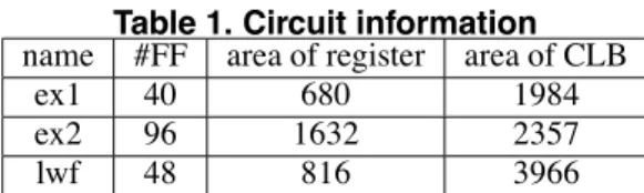
Table 1. Circuit information name #FF area of register area of CLB
ex1 40 680 1984
ex2 96 1632 2357
lwf 48 816 3966
If a sequential circuit satisfies Definition 5, the sequential circuit is said to be extended acyclically testable sequential circuit. If the product of the maximum height of thru trees in TTTJand TTTPand the depth of dependency in the set of thru trees TTT = TTTJ∪ TTTPis a constant, Definition 5 corresponds to the definition of acyclical testability except in regard to thru trees. Furthermore, the thru tree defined in [7] is also any of justification and propagation thru trees. Therefore, we have the following theorem.
Theorem 1: The class of extended acyclically testable se- quential circuits is a super set of the class of acyclic sequen- tial circuits[7].
Based on the above, it is possible to conjecture as follows. Conjecture : Test generation complexity of extended acycli- cally testable sequential circuits isτ2-bounded.
This proof is a future work.
4 Case studies
We show the effectiveness of the proposed class by our ex- periments, using SUN blade2000 workstation (UltraSPARC- III+, CPU 1.02GHz, Memory 2GB). For three sequential cir- cuits shown in Table 1, we attempted three types of DFTs: full-scan design (FS), acyclically testable design (AT) and extended acyclically testable design (EAT). In FS, all reg- isters are replaced with scaned-FFs. In AT and EAT, some thru functions are added to CLBs so that a given circuit be- comes acyclically testable and extended acyclically testable, respectively. After the DFTs, we generated a TEM for each CLB in each sequential circuit. Note that, in FS, a TEM for a CLB corresponds to the CLB. Target faults of each circuit were faults in each CLB and wires between elements in the circuits. In a TEM, some CLBs appear more than once, e.g., CLB1 appears at time frames 0 and 1 in the TEM as shown in Fig. 5. Therefore, a single fault in a CLB of a sequential cir- cuit is mapped to a multiple fault in the corresponding TEM. In our experiments, we converted such a multiple fault into a single fault by the method of [8] and employ TetraMax (Synopsys, Inc.), which is a combinational TPG for single stuck-at faults. The circuit size was estimated provided that the area size of an inverter is one. We achieved 100% fault efficiency for all the circuits with three DFTs.
Table 2 shows area overhead, test application cycle, num- ber of test patterns, test generation time and total size of TEMs. TEMs are performed by the definition [7], for AT and EAT. Column area overhead shows the difference of the circuit size before and after the DFTs. The test applica- tion cycle shown in the fourth column for FS is calculated by(number o f test patterns) × ((number o f FFs) + 1) + (number o f FFs)), and that for AT and EAT is calculated by(number o f test patterns) × (length o f T EM). Column
Table 2. Case studies
name method area overhead test application number of test generation total size
cycle test pattern time(s) of TEMs
FS 280 2336 56 0.02 1984
ex1 AT 73 336 56 0.06 1984
EAT 49 348 58 0.22 2700
FS 672 4073 41 0.06 2357
ex2 AT 96 280 56 0.12 2357
EAT 48 288 48 1.02 4343
FS 336 3527 71 0.20 3966
lwf AT 145 492 82 0.37 3966
EAT 97 426 71 1.23 5484
TEM area denotes the sum of the size of TEM for each CLB in a circuit. Note that the size of a TEM does not include that of the CLBs on thru trees because the root (a leaf) of a justi- fication (propagation) thru tree can be regarded as a primary input (output).
From Table 2, we can see the followings. The area over- head for AT and EAT is smaller than that for FS. Moreover, our method, EAT, needs smaller area overhead than AT. This is because the number of thru functions required by EAT is less than that of AT. The test application cycle for AT and EAT is smaller than that for FS since AT and EAT do not need scan operation. The test application cycle for EAT is comparable to AT.
Three DFTs are comparable in the number of test patterns. For ex2 and lwf, the number of test patterns of EAT can be small as compared with AT. The reason is that TEMs of EAT is often implemented justification and propagation of values without using thru functions. Because the number of thru functions required for EAT is less than that of AT. Therefore, the one test pattern of EAT can find many faults compared with that of AT.
For ex2, although the number of test patterns for EAT is smaller than AT, the test application cycle for EAT is not. This is because the sum of the length of TEMs for EAT is greater than that for AT. The total size of TEMs for EAT is larger than that for AT. In EAT, instead of thru functions, the logic of CLBs is used for justification and propagation as fre- quently as possible. As a result, the size of TEMs for EAT is larger than that for AT, so that the test generation time for EAT increases. However, since a TEM is a combinational circuit, we can achieve complete fault efficiency with practi- cal time.
5 Conclusion
In this work, we proposed the extension of the class of acyclically testable sequential circuits whose the test genera- tion complexity isτ2-bounded. In the new class, we defined justification and propagation thru trees instead of the thru trees presented in [7] and proposed the sufficient conditions of the class. Case study show that the area overhead of ex- tended acyclically testable sequential circuits is smaller than that of the acyclically testable sequential circuits, and com- plete fault efficiency is achieved as well as the acyclically
testable sequential circuits.
Our future work is evaluation and experiment of larger circuits, analysis of test generation complexity of extended acyclically testable sequential circuits. We are now making further experiments for large circuits. We can expect that the experimental results also show the effectiveness of our improvement. The final manuscript will include the experi- mental results.
Acknowledgments
The authors would like to thank the members of Com- puter Design and Test Laboratory, Nara Institute of Science and Technology, Japan and Dr. Yuki Yoshikawa and other members of Computer Design Laboratory, Hiroshima City University, Japan for their valuable comments.
References
[1] P. Goel,“ Test generation costs analysis and projections, ”Proc. 17th DAC, pp. 77-84, June 1980.
[2] M.R. Prasad, P. Chong, and K. Keutzer,“ Why is ATPG easy? ”Proc. 36th DAC, pp. 22-28, June 1999.
[3] C. Y. Ooi and H. Fujiwara, ”Classification of sequential circuits based onτknotation,” IEEE Proc. 13th Asian Test Symp., pp.348-353, Nov. 2004. [4] C. Y. Ooi, T. Clouqueur and H. Fujiwara, ”Classification of sequential circuits based onτknotation and its applications”, IEICE Trans. on Info. and syst., pp.2738-2747, Dec. 2005.
[5] R. Gupta and M. A. Breuer,“ The BALLAST methodology for struc- tured partial scan design,” IEEE Trans. Comput., vol. 39, no. 4, pp. 538-544, April 1990.
[6] H. Fujiwara,“ A new class of sequential circuits with combinational test generation complexity,” IEEE Trans. Comput., vol. 49, no. 9, pp. 895-905, Sept. 2000.
[7] C. Y. Ooi and H. Fujiwara, ”A new class of sequential circuits with acyclic test generation complexity,” IEEE Proc. ICCD, pp.425-431, Oct. 2006.
[8] H. Ichihara, and T. Inoue, ”A method of test generation for acyclic sequential circuits using single stuck-at fault combinational ATPG,” IEICE Trans. Fundamentals, Vol. E86-A, No. 12, pp. 3072-3078, Dec. 2003.