A Response Compactor for Extended Compatibility Scan Tree Construction
Zhiqiang You* Jiedi Huang Michiko Inoue Jishun Kuang Hideo Fujiwara
Abstract1:Though test application time and test power is reduced drastically in the extended compatibility scan tree, the number of output is too large. This paper proposes a response compactor to reduce its output number as well as the test response data volume. This compactor is composed by an XOR network. Exploring the characteristic of extended compatibilities and the structure information of the circuit under test, it can effectively solve error diffusion problem, and achieves low hardware overhead. Experimental results show the applicability of the response compactor. As for the ISCAS’89 benchmark circuits, the compactor can have the highest compression ratio to 77 while keeping the same fault coverage.
Keyword: design for testability, full scan testing, scan tree, test response compaction, XOR network
I. Introduction
As the VLSI chips become complex, the test generation time and test cost increase rapidly. Now, the cost of testing an integrated circuit(IC) accounts for a considerable proportion of the cost of the IC[1]. Many design for testability (DFT) methodologies[2] have been proposed to guarantee high fault coverage and to reduce the test cost effectively.
Full scan design is a very important technology in the DFT methodologies. By connecting all the scan cells of a circuit as a chain and adding a test mode, full scan design reduces test generation time drastically. However, its test application time is very long and test data volume is quite large. The techniques in [3-5] reduce the test application time and test data volume in scan test by cutting the scan chain into some sub-chains to shift in the test vector simultaneously. These multiple scan chain technologies increase the number of inputs and outputs, and occupy the limited number of the pins in a chip. Therefore the compaction of the number of outputs in multiple scan chain designs becomes more necessary. Assume a compactor has n inputs and m outputs, where n, m are natural numbers, n>>m. Many compactors have been proposed for multiple scan chain designs. X-Compact [6] has been proposed based on an XOR network. It guarantees that when two or any odd number of errors appear at the compactor inputs at the same time, there will be no aliasing happens. Block compactor [7] makes several scan cycles data as a block to be compacted, and it can achieve high compaction ratio with less aliasing. Convolutional compactor [8, 9] uses an XOR network and a no-feedback shift
This work is supported in part by the National Natural Science Foundation of China (NSFC) under grant No. 60673085, 60773207.
Zhiqiang You is with Software School, Hunan University, Changsha, 410082 China (e-mail: zq_you@163.com).
Jiedi Huang and Jishun Kuang are with School of Computer and Communication, Hunan University, Changsha, 410082 China (e-mail: {kidhuang700, jshkuang}@hotmail.com).
Michiko Inoue and Hideo Fujiwara are with Nara Institute of Science and Technology, Ikoma, Nara 630-0192, Japan (e-mail: {kounoe, fujiwara}@is.naist.jp).
register chain to implement the logic circuit of convolution operation. In [9], after analyzing the fault responses of the benchmark circuit, it found that most faults are only sensitized to less scan cells (generally less than 4), which makes the design based on the XOR network suit to multiple scan chain technologies.
Recently, scan tree technologies[10-14] have been proposed to reduce test application time and test power. Scan tree technologies construct the scan cells to a tree structure. In scan shift operations, via the root node, which corresponds to a scan cell, test data is shifted into each node of scan tree. Scan cells in the same level have the same test data. Therefore, to keep fault coverage, the test data of the scan cells in the same level should be compatible. Compared to single scan chain construction, scan chain techniques reduce the length of the longest scan chain in the circuit. Thus, it can reduce test data volume and test application time. However, in scan tree construction there are a lot of scan outputs. Furthermore, in scan shift operations after test response is captured, the inner nodes of a scan tree will diffuse theirs values to several outputs at the same time. It will make aliasing happen easily during compaction and be hard to design a compactor. To resolve such a problem, [15] extended the concept of compatibilities in [11-14], and proposed an extended compatibility scan tree construction. This method can reduce test application time and test power effectively. Nevertheless, it increases the number of scan output as well as the test response data volume.
To reduce the number of scan outputs, this paper proposes a novel test response compactor for extended compatibility scan tree construction. The proposed compactor is composed by an XOR network. Furthermore, we reduce the number of scan outputs more by considering the structure information of the circuit under test (CUT).
The rest of this paper is organized as follows. In section 2, the structure of an XOR network is described. In section 3, we show how to reduce the number of scan outputs using the structure information of CUT. Section 4 shows how to construct a compactor for extended compatibility scan tree construction. Section 5 reports on some experimental results for our proposed compactor. Section 6 concludes with a brief summary.
II. Preliminaries A. Extended Compatibility Scan Tree
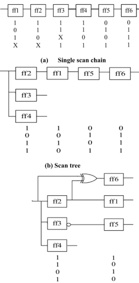
Figure 1(a) shows a single scan chain which has 6 scan cells and it test set with X’s, where X denotes a don’t care bit. According to normal compatibility[15], the scan chain can be constructed to a scan tree shown in Figure 1(b). The length of the longest scan chain is reduced to 4. Test application time is reduced 1/3. From Figure 1(b) we can see that for each test vector, the value of scan cell ff1 is complementary with that of ff6, the value of ff6 can be that of ff1 XOR that of ff4 . We can reduce test application time more by employing NOT-, XOR-
_____________________________ 609 978-1-4244-3870-9/09/$25.00 ©2009 IEEE
IEEE 8th International Conference on ASIC (ASICON2009), pp. 609- 612, Oct. 2009.
and NXOR compatibilities[15]. The extended compatibility
scan tree and it test set is shown in Figure 1(c). I1 I2 I3 I4 I5 I6 I7 I8 O1
ff5
ff1 ff2 ff3 ff1ff4 ff1ff6
输入 输出
1 1 1 1 0 0
0 1 1 1 1 1
1 0 X 0 0 1
X X 1 1 1 1
O2
(a) Single scan chain
1 1 0 0
0 0 1 1
1 1 0 1
1 0 1 1
ff2
ff3
ff4
ff1 ff5 ff6
(b) Scan tree
1 1
1 0
0 1
1 0
ff2
ff3
ff4
ff1 ff6
ff5
(c) Extended compatibility scan tree
Figure 1. Extended compatibility scan tree and its test set
B. XOR Network
Figure 2(a) shows the structure of an XOR network with eight inputs and five outputs. A single input is diffused to multiple outputs by XOR network. The inputs and outputs of the XOR network showed in Figure 2 (a) satisfy the following relations.
3 2 1
1 O O O
I = + + (1)
4 3 2
2 O O O
I = + + (2)
4 3 1
3 O O O
I = + + (3)
4 2 1
4 O O O
I = + + (4)
5 4 1
5 O O O
I = + + (5)
5 3 1
6 O O O
I = + + (6)
5 4 3
7 O O O
I = + + (7)
5 4 2
8 O O O
I = + + (8) These equations are named as correlative polynomials. They denote the value of an input of a compactor can be propagated to which outputs. As shown in Equation 1, input I1 will diffuse to the outputs O1, O2, O3. The correlative matrix is shown in Figure 2(b). In the matrix, 1 means that the input and output are associated and 0 means that they are not associated.
(a)An XOR network
⎥⎥
⎥⎥
⎥⎥
⎦
⎤
⎢⎢
⎢⎢
⎢⎢
⎣
⎡
=
00001111 01111011 11100110 11010001 10111100
H
(b) Correlative matrix
Figure 2. An XOR network and its correlative matrix
III. Reduce the Number of Scan Outputs Using the Structure Information of CUT
This section will describe the following definition and theorem to show how to reduce the number of scan outputs using the structure information of CUT.
Definition 1. We call a sub-path including a leaf node and any other node whose out degree is exact one as a unique sub-path.
For example, as shown in Figure 3, the sub-path (m, o) is a unique sub-path. (m, o, and q) is a maximal unique sub-path. Every leaf node has one maximal unique sub-path. The maximal unique sub-paths of leaf nodes m, f and e are (m, o, q), (f) and (e) respectively.
Figure 3 Extended compatibility scan tree
Theorem 1. We can add an XOR gate between two leaf nodes to reduce the number of scan outputs if the 1&(2|3|4) conditions are satisfied without losing fault coverage.
1. Any nodes that have the same sequential depth in their maximal unique sub-paths have no common predecessor in the combinational part of the CUT.
2. The head nodes ni1, ni2 of their maximal unique sub-paths have different sequential depths.
a c b
e d f
g i h
k j
m l o n
q p
r
O3 O4 O5
610
3. The head nodes ni1, ni2 of their maximal unique sub-paths have the same sequential depth and they have no common parent node.
4. The head nodes ni1, ni2 have a common parent node and there exists a sibling node excluding themselves.
For example, as shown in Figure 3, the maximal unique sub-paths of nodes m and l are (m, o, q) and (l, n, p) respectively. If nodes m and l, o and n, q and p have no common predecessor in the combinational part, though the head nodes q and p have the common parent node r, the scan output m and l can be connected together via an XOR gate because node k is a sibling of nodes q and p.
If scan outputs a and b, e and d, m and l can be connected together by an XOR gate to form a new output respectively, the number of scan outputs is reduced from 8 to 5 as shown in Figure 3. The number of scan outputs can be reduced by checking the scan outputs using Theorem 1.
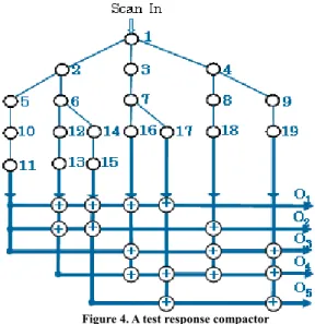
IV. Test Response Compactor for Extended Compatibility Scan Tree Construction In scan tree techniques, the scan cells are constructed into a tree structure. This technique has large numbers of output ports, and the value captured by a scan cell might be propagated to multiple scan outputs, which brings much difficulty to compact the outputs of the scan tree. As shown in Figure 4, the error captured by scan cell 6 will propagate to scan outputs 13 and 15. Figure 4 gives a possible compactor design which will introduce in the following subsection.
Figure 4. A test response compactor
A. Design a Compactor for Scan Tree Construction
As shown in Figure 4, the response of node 6 can be propagated to scan outputs 13 and 15. Though the response of node 6 can be propagated to O1, O2, O4, O5, its error response can only be observed by O4, O5. This can be expressed using the following binary addition. The correlative polynomials of outputs 13 and 15, which are inputs of the XOR network, denoted in binary are I13=11010 and I15=11001. I13+I15=00011,that means the captured value of node 6 can be only propagated to the outputs O4 and O5. Therefore, every
node of the scan tree will have a correlative polynomial to show the relation with the outputs of the compactor.
According to a theorem in [6], if each column in the correlative matrix is distinct and has the same odd numbers of 1, then the compactor can detect the fault when two or any odd numbers of errors occur at the same time in absence of X’s. The number of inputs n and outputs m of a compactor should meet the following condition:
n
Cmk >= (9) where k is the number of outputs which are correlative to an input.
As shown in Figure 4, the compactor has 7 inputs. According to Expression 9, we choose the correlative polynomial set with output number is 5, and k=3. The correlative polynomial set has 10 correlative polynomials.
The process to design a compactor of a scan tree can be dealt to the process to assign an appropriate correlative polynomial to each scan tree output. That is equivalent to ascertain the correlative relationship between the scan outputs and the compactor outputs. The next paragraph will describe how to assign the correlative polynomial to the scan outputs.
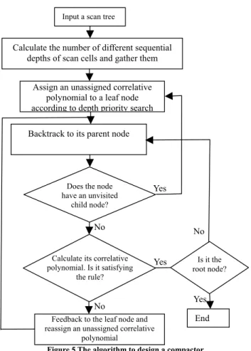
During shifting out, the response of a scan cell of scan tree might be propagated to some outputs several times at different scan cycles. For example, the response of scan cell 1 in Figure 4 can be shift out in the 4th and 5th scan shift cycles. The sequential depths set of scan cell 1 is {4, 5}. We group the scan cells, which have the same sequential depths set, into a sequential clique. For example, scan cells 3, 4, 5, and 6 in Figure 4, are grouped in a sequential clique. During assigning the correlative polynomial to an output of a scan tree, it has to satisfy the following rule. The correlative polynomial of the scan cells in the same sequential depths set of a scan tree is distinct to guarantee to produce errors when two scan cells captured errors, while the correlative polynomial cannot be zero if the size of a scan cell’s sequential depths set is one. The algorithm to design a compactor is described in the following steps shown in Figure 5.
Step 1: Input a scan tree which is constructed by [16]; Step 2: Calculate the number of different sequential depths for each scan cell and gather the scan cells which have the same sequential depths set;
Step 3: Assign an unassigned correlative polynomial to a leaf node according to depth priority search;
Step 4: Backtrack to its farther node;
Step 5: If the node has an unvisited child, goto Step 3; Step 6: Calculate its correlative polynomial. If it does not satisfy the rule, feedback to the leaf node and reassign an unassigned correlative polynomial, then go to Step 4. If it is not the root node, then go to Step 4;
Step 7: Terminate the algorithm with the assigned correlative polynomials.
B. Design a Compactor for Extended Compatibility Scan Tree The input value of the scan cells in an XOR/NXOR- compatible clique is obtained by XOR inputs of two compatible cliques in two different level of a scan tree. The XOR/NXOR-compatibility brings the characteristic that the inner nodes of a scan tree have several sequential depths. Such characteristic will release the restriction during
611
Figure 5 The algorithm to design a compactor
constructing a compactor. As shown in Figure 3, since the extended compatible clique node a, the size of sequential depths set of node j is increased to two. Increasing the size of sequential depths set of a node makes its captured error can propagate to the input(s) of the compactor through several paths with different sequential depths.
The technique which employs XOR- and NXOR-compatibilities efficiently reduces test application time and test power though it needs a lot of leaf nodes. Furthermore, it also improves the observability of inner nodes in a scan tree, which benefits the design of a compactor.
V. Experimental Results
We have conducted experiments on the full scan version of larger ISCAS’89 benchmark circuits in C language on a PentiumIV2.4GHz with 512 MB RAM. In the experiments, we use the ATPG tools “TestGen” of Synopsys to generate test cubes and HOPE simulator to perform fault simulation.
Table 1. Results for the proposed test response compactor
Table 1 shows the results for the proposed test response
Input a scan tree
compactor. The first four columns describe the circuit’s names, the number of faults, the fault coverage, and the number of scan outputs of extended compatibility scan tree. The next three columns give the experimental results about the number of outputs in the proposed compactor, the number of outputs which are correlative to an input (“#K”), and the number of alias. From table 1, we can see that the number of outputs is reduced drastically without losing fault coverage. For S35932, the compression ratio is about 77X.
Calculate the number of different sequential depths of scan cells and gather them
Assign an unassigned correlative polynomial to a leaf node according to depth priority search
Backtrack to its parent node
VI. Conclusions
This paper proposes a response compactor for extended compatibility scan tree construction. The proposed compactor is composed by an XOR network. Our approach, which takes advantages of extended compatibility scan tree and uses the structure information of the CUT, is effectively to solve the problem introduced by the diffusing of errors, to reduce the number of outputs, and to achieve low hardware overhead.
Does the node have an unvisited
child node?
Yes
No No
References
[1] W. Chen, M.R. Sudhakar, P. Irith, ” On Compacting Test Response Data Containing Unknown Values”, In Proc. IEEE ICCAD, pp. 855-862, 2003
[2] H. Nagle, “Design for Testability and Built-In Self-Test: A Review” IEEE Trans. on Industrial Electronics, 36 (2),pp. 129-140, 1989 [3] B. Arsian and A. Orailoglu. “CircularScan: A Scan Architecture for
Test Cost Reduction”, In Proc. IEEE DATE, 1290-1295, 2004 [4] Z. You, T. Iwagaki, M. Inoue and H. Fujiwara, “A Low Power
Deterministic Test Using Scan Chain Disable Technique” IEICE Trans. on Information & Systems, E89-D(6):1931-1939, 2006
[5] J. Saxena, K. M. Butler and L. Whetsel, “An Analysis of Power Reduction Techniques in Scan Testing “ ,In Proc. IEEE ITC, 670-677,2001
[6] S. Mitra, K. S. Kim. “X-Compact: An Efficient Response Compaction Technique”, IEEE Trans. Computer-Aided Design of Integrated Circuits & Systems, pp.421-432,2004
[7] C. Wang, S. M. Reddy, I. Pomeranz, J. Rajski and J. Tyszer, “On Compacting Test Response Data Containing Unknown Values”, In Proc. IEEE ICCAD, pp. 855-862,2003
[8] Y. Han, Y. Xu, A. Chandra, H. Li and X. Li, “Test Resource Partitioning Based on Efficient Response Compaction for Test Time and Tester Channels Reduction “ In Proc. IEEE ATS, pp. 440-445,2003
[9] J. Rajski, J. Tyszer, C. Wang and S. M. Redy, “Finite Memory Test Response Compactors for Embedded Test Applications” IEEE Transactions on Computer-Aided Design, pp.622-634,2005
[10] D. Xiang, S. Gu, J. Sun and Y. Wu, “A Cost-Effective Scan Architecture for Scan Testing with Nonscan Test Power and Test Application Cost” In Proc. ACM/IEEE DAC, pp.744-747,2003 [11] K. Miyase and S. Kajihara, “Optimal Scan Tree Construction with Test
Vector Modification for Test Compression” In Proc. IEEE ATS, pp. 136-141,2003
[12] H. Yotsuyanagi, T. Kuchii, S. Nishikawa, M. Hashizume, K. Kinoshita,
“Reduce Scan Shifts Using Folding Scan Trees” In Proc. IEEE ATS, pp. 6-11,2003
[13] Y. Bonhomme, T. Yoneda, H. Fujiwara and P, “Girard. An Efficient Scan Tree Design for Test Time Reduction” In Proc. IEEE ETS, pp. 174-179,2004
[14] K. Miyase, S. Kajihara and S. M. Reddy, “Multiple Scan Tree Design with Test Vector Modification” In Proc. IEEE ATS, pp. 76-81,2004 [15] Z. You, M. Inoue, H. Fujiwara, “Extended Compatibilities for Scan
Tree Construction” Digest of papers, IEEE ETS, pp. 13-18 ,2006 [16] Y. Cheng, Z. You, J. Kuang, “Test Response Data Volume and Wire
Length Reductions for Extended Compatibilities Scan Tree Construction”, In Proc. IEEE DELTA, pp. 308-313, 2008
Circuits #Fault #FC(%) #S-out #C-out #K #Alias
S1423 1515 99.076 32 7 3 0
S5378 4551 99.121 47 6 3 0
S9234 6927 93.475 70 7 3 0
S13207 9815 98.462 261 10 3 0
S15850 11725 96.682 240 10 3 0
S35932 39094 89.809 1013 13 5 0
S38417 31180 99.442 680 10 5 0
S38584 36303 95.741 414 11 5 0
Feedback to the leaf node and reassign an unassigned correlative
polynomial No
Is it the root node?
End Yes
Yes Calculate its correlative
polynomial. Is it satisfying the rule?
612