Covalent Organic Frameworks
JIN ENQUAN
Doctor of Philosophy
Department of Structural Molecular Science
School of Physical Sciences
SOKENDAI (The Graduate University for
Advanced Studies)
定
Chapter 1. General Introduction
–––––––––––––––––––––––––––––––––––––––––––––––––––––––––––––––––––––––––––––––
Chapter 1
General Introduction
1.1 Covalent Organic Frameworks
Progress over the past decadesin the field of chemistry has greatly expanded the freedom of design and synthesis of polymers. The development of new catalysts and reaction systems enables the elaborate structural control over polymer chains from the perspectives of molecular weight, chain end, chain sequence, and stereochemistry. However, the structural control of polymers is largely limited to the level of primary-order structure; synthetic control over high-order structures remains a challenge in the field of chemistry.
Biological polymer systems such as proteins, DNA and RNA utilize encoded systems that allow for the covalent linkage of monomers into sequenced primary-order chains and specific noncovalent interactions for the organization of well-defined high-order structures. The elaborate combination of covalent bonds and noncovalent interactions in the biological systems enables the control of not only primary-order but also high-order structures. Such a structural control of a synthetic polymer is an ultimate goal of polymer science.
In synthetic polymer systems, to confine the chain growth in a two-dimensional (2D) manner offers an elegant way to reduce the complicated chain entangle problem that is observed for most of linear polymers. 2D covalent polymers require the control of chain growth strictly over the 2D plane and need the connection of each monomer in a specific direction, while repeating this guided link pattern will eventually lead to the generation of controlled primary order structures with well-defined topology. This directionally guided covalent bonding leaves the generation of discrete topology of 2D polymers and well-ordered pores. To fulfil this polymerization pattern, monomers are required to have rigid structures with reactive sites that are distributed to form a specific geometry. Because most of the rigid organic molecules consist of π-backbones, the 2D covalent polymers with rigid π-backbones with well-defined topology can direct the noncovalent interactions through the π-π-interaction of π-skeletons of the 2D polymer layers. This guided noncovalent interaction generates
Chapter 1. General Introduction
–––––––––––––––––––––––––––––––––––––––––––––––––––––––––––––––––––––––––––––––
periodically ordered πcolumns and one-dimensional (1D) channels.1-2Therefore, COFs are a class of covalent polymer that enable the synthetic control over primary and high-order structures. As fully predesigned synthetic polymers, COFs have emerged as a molecular platform for structure design and functional development. These structural features make a distinct contrast to any other porous materials thus far developed.
The skeleton structural of COFs can be designed by using different monomers with different geometry, reactive sites and size. Up to date, a diversity of COFs with different topologies, π-systems, and linkages has been developed. Moreover, the pores of COFs can be designed by using either the structural design of monomers or the pore-wall surface engineering. The pore size, shape and pore wall environments can be fully predesignable and synthetically controllable. These two distinct features associated with the structural design make COFs very attractive as a molecular platform for structural design and functional development.
1.1.1 Design and Synthesis
1.1.1.1 Topological Design of Frameworks
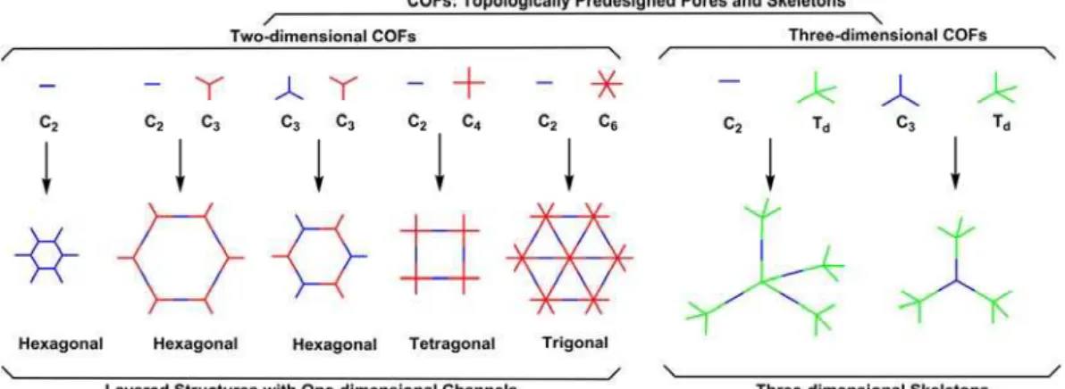
Figure 1. The combination of building blocks with different geometries to design 2D and 3D COFs.
Figure 1 shows the design principle of COFs. COFs can be designed using topology diagram that combines the different geometries of monomers to direct the different growth pattern of the polymer skeletons. For example, the geometry combination C2 + C3could design hexagonal COFs, while self-condensation of C2or C3 + C3 could generate hexagonal COFs but with different pore sizes and skeletons.3-4 Up to date, hexagonal, tetragonal, rhombic, trigonal and kagome topologies of COFs have been developed by designing the different geometry of monomers.
1.1.1.2 Dynamic Covalent Chemistry
Dynamic covalent chemistry (DCC) with reversible reactions could introduce a series of bond formation, broken and re-formation steps mechanism to the reaction systems, which are required for the COFs synthesis because these processes enable the structural self-healings.5The self-healing mechanism reduces the possibility of structural defects and helps to form crystalline structure, while the reversible reaction provides a thermodynamically control over the final polymer structures.This synthetic principle is applicable to all COFs, irrespective of their topology, π-units and linkages.
1.1.1.3Synthetic Reaction and Linkage
As discussed above, the synthetic reaction used in the formation of COFs should be a reversible reaction. The reversibility of the synthetic reaction directly determines the crystallinity or structural orderings of COFs. Figure 2 shows the different linkages developed thus far for the synthesis of COFs.
Boronate ester linkage is formed from the reaction of boronic acid and catechol that enablesthe synthesis of high crystalline COFs owing toits reaction reversibility. Boroxine linkage could be established through the self-condensation of boronic acid. This reaction is benefit for the construction of small pore high crystalline COF.6-7
Integration imine linkage to the COFs skeleton through the condensation reaction
Chapter 1. General Introduction
–––––––––––––––––––––––––––––––––––––––––––––––––––––––––––––––––––––––––––––––
of aldehyde and amine could resulted in COFs with enhanced stability compared to boronate and boroxine linkages.8Especially, the imine linkage could improve the COFs stability in the presence of water, acids and bases. The hydrazone linkage from the condensation between aldehyde and hydrazide groups is similar to the imine linkage with high stability.9Moreover, combination of two different linkages, such as imine, boronate ester, boroxine and hydrazone, results in new concept of double-stage strategies. Double-stage linkage is useful for the synthesis of hexagonal, tetragonal and rhombic-shaped COFs.10
Azine linkage from the condensation reaction between aldehyde and hydrazine groups is usually used for the synthesis of small micropores COFs.11The resulting COFs are stablein organic solvents.
Condensation between quinine and amine groups catalyzed by acids forms phenazine-linked COFs with highly π-conjugated and stable structures.12 Imide-linked COFs also could be synthesized through the condensation between dianhydrides and amines at relative high temperatures up to nearly 150-200 oC with high surface area.13-14Moreover, covalent triazine frameworks (CTFs) are crystalline porous polymers that are prepared from the self-condensation of nitrile groups in the presence of Lewis acid catalyst at high temperature such as 400 C.15-16
Squaraine-linkage from the condensation of squaric acid and amine could be used for Ionic COFs formation.17The condensation between diol with trialkyl borate in the presence of base catalyst results in the formation of spiroborate-linked COFs.18
1.1.1.4 Synthetic Methods
The reversibility of the condensation reaction is the critical for the COFs formation. In this context, the control of reaction conditions is important because they affect greatly the reversibility. Especially, under solvothermal control, the reaction media such as mixture of several solvents with different ratios and reaction conditions including temperature, catalyst, template, reaction time and pressure are important factors to be considered that affect the formation of crystalline porous COFs.19
The widely used solvothermal synthesis protocol is shown as follow: Monomers andmixture of organic solvents are placed in a Pyrex tube and degassed with several times. Then the Pyrex tubeis sealed and heatedat a certain reaction temperature for a certain period. After the reaction completes, the precipitate is collected, washed with suitable solvents, and dried under vacuum to yield bulk powder of crystalline COFs.
For the ionothermal conditions, molten salts, such as zinc chloride, have been developed as reaction media. The CTFs were synthesized under ionothermal
Chapter 1. General Introduction
–––––––––––––––––––––––––––––––––––––––––––––––––––––––––––––––––––––––––––––––
Figure 3. Schematic representation of COFs with triazine linkages.
Microwave assisted technique is useful foraccelerating the COFs synthesis. Unlike solvothermal method, microwave synthesis could be used for quick and large-scale preparation of COFs (Figure 4).21-23
O O
O H N NH O
O O
HN
NH
HN
O O
O
NH
O O
O NH
HN O
O O
NH HN NH
O O
O HN
HN HN
NH
NH
NH
HN
Figure 4. Chemical structure of microwave synthesized TpPa-1.
By introducing mechanochemical synthesis to the COFs formation, certain COFs could be prepared without reaction solvents at room temperature in air.For example, TpPa-1 (MC), TpPa-2 (MC) and TpBD (MC) COFs (Figure 5), could be obtained through mechanochemical method. The morphology of these COFs is2D with exfoliated layers.24
NH O
O O
HN NH
HN NH
O O
O NH
O O
O H N
HN NH
HN O
O O
NH
NH HN
O O
O NH
HN NH
HN
O O
O H N
Figure 5. Chemical structure of mechanochemical synthesized TpBD.
With the in situ film growth method and vapour-phase reaction film growth method, single or multi-layer COFs films could be fabricated on the various substrates, such as copper, graphene, gold, Al2O3, silicon and silver.25,26
Chapter 1. General Introduction
–––––––––––––––––––––––––––––––––––––––––––––––––––––––––––––––––––––––––––––––
1.1.2 Structural Study
COFs are highly crystalline porous polymers with well-defined X-ray diffraction (XRD) patterns. Based on the experimentally observed XRD data, the crystalline structure of COFs could be deducted. The simulated XRD patterns of COFs with different stacking ways could be used to match with experimental observed XRD patterns to reveal the COFs crystalline structures.Combining with other measurements includinginfrared spectroscopy, elemental analysis, energy dispersive spectrometer, Raman spectroscopy, solid-state NMR spectroscopy and X-ray photoelectron spectroscopy could results in more discrete structure information about linkages, terminal groups, and compositions of the COFs.
1.1.2.1 Topology
Up to date, many organic building blocks with different geometries, such as C2, C3, C4 and C6, have been synthesized for framework knots, and C2- and C4-symmetric blocks have been developed as linker parts. Based on the target shapes and sizes of the COFs frameworks, we can exactly choose the right or appropriate organic units. With the continuously development of divert building blocks, COFs with different geometry of pores, such as hexagonal,27-29tetragonal,30-32 rhombic pores,33 trigonal pores,34 dual- and triple-pore kagome structures,35-36 and dual-pore hexagons,37 could be precisely obtained.
1.1.2.2 Alignment of Layers
2D COFs are formed through the π-stacking of 2D planar sheets. The planar sheets aligned in parallel to form layered structurethat could be directly visualized by using high-resolution tunnelling electron microscopy.38The relative positions of the neighbouringsheets exist several possibilities. To access to this problem,
information about the distance and horizontal offset between layers through energy optimization. To check the simulating result with experimental result, the unique alignment of the 2D COF layers could be explained.
Another approach is based on the density-functional based tight-binding (DFT-B) method.39The simulated XRD patterns showed nearly the same results as the experimentally observed XRD patterns. The stacking energies of these COFs would be different based on the offsets. For example, the results also gave the result that when the 2D COFs (COF-5) structures obtained an offset about 1.4 Åbetween the layers, the structures were easily formed and resulted in more attractive Coulomb interlayer interactions than eclipsed stacking.
By using the unit cell of each space group of computational simulations, the XRDpatterns of crystalline COFs could be predicted. Comparing the simulated XRD patterns with experimentally observed profiles, the suitability of the chosed space group could be evaluated.
1.1.2.3 Channel Structure
COFs possess discrete polygons and their pores have clear shapes, such as hexagonal, tetragonal, trigonal, rhombic and kagome structures.Based on the monomer structures, the pores of COFs could be predesigned through a wide range of sizes from micropores tomesopores. The well-defined layered structures of 2D COFs yields ordered 1D channels. By modulating size and geometry of the monomers, the 1D channels of COFs could be precisely controlled.
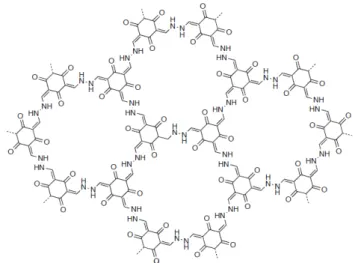
For 2D COFs, the first reported microporous COF-1 is boroxine linked COF, with a pore size about 0.86 nm,1 which formed through the self-condensation of BPDA.PC-COF is the hexagonal pores COF, with a relative high mesopore about 5.8 nm with imine linkage.40It is reported that dual-pore kagome-type COFs contain two different sizes of pores (Figure 6). One is micropores and the other is mesopores.35These 2D COFs with controllable identical pores could be effectively
Chapter 1. General Introduction
–––––––––––––––––––––––––––––––––––––––––––––––––––––––––––––––––––––––––––––––
used for different kinds of gas storage, such as hydrogen, methane, water, ammonia and carbon dioxide.
Figure 6.Chemical structure of dual-pore kagome-type COF.
1.1.3 Functions and Properties
The porosity and chemical structure of skeleton decide the functionality of COFs. With the unique properties, COFs have been developedfor various applications, such as gas absorption, catalysis, energy transfer, electron transfer, energy storage. With the highly ordered layer structures of 2D COFs, a series of functional π-unitscan be easily introduced to the skeletons to design π-columnar arrays, which provide a good platform for synthesizing novel organic semiconducting materials with highly ordered structures.
1.1.3.1 Gas Adsorption, Separation and Storage
COFs are composed of lightweight elements (such as C, H, O and N) and connected with strong covalent bonds. Together with their structural designability, COFs have emerged as an attractive platform for deigning porous materials for gas storage, separation and storage.
Although there are reports on COFs for gas storage of hydrogen, methane, acetylene, ammonia and carbon dioxide, the design strategy is nearly the same. For gas storage, control over the skeleton composition, the pore size and functional groups are the general strategy for the design of COFs.
For example, considering the small pore size is benefit for CO2 absorption, a series of small pore size COFs have been synthesized through the predesign of COFs skeletons.The azine-linked ACOF-1 exhibits CO2 absorption up to 17.7 wt% with a pore size about 0.94 nm.41 Another azine-linked COF, COF-JLU-2 shows CO2 uptake of 21.7 wt% with 0.96 nm pore size.42 The imine linked TpPa-COF also presents high CO2 absorption about 21.8 wt% with 1.3 nm pore size.43 HEX-COF-1 with a pore size of 1.1 nm, could achievea capacity of 20.0 wt%.44 All these CO2 absorptions are obtained at 273 K and 1 bar.
Figure 7.Chemical structure of COF-JLU-2.
Chapter 1. General Introduction
–––––––––––––––––––––––––––––––––––––––––––––––––––––––––––––––––––––––––––––––
1.1.3.2 Heterogeneous Catalysis
When loading catalytic active sites to the pore structures, COFsoffera designable platform for heterogeneous catalyst.45With the surface engineering method, a variety of heterogeneous catalysts systems have been developed. For example, incorporating chiral pyrrolidine organocatalytic sites to the mesoporous porphyrin COFs, yielded a chiral COF, which serves as catalyst for Michael addition reactions. The highest reactivity enabled to finish the reaction in 1 h.46Introducing the same catalytic center to large pore size hexagonal COFs generates another heterogeneous system. Unlike the porphyrin COF system, the hexagonal COF exhibits relative high porosity and large pores and could enhance the catalytic activity of asymmetric Michael addition reactions up to 100% conversion in 12 hours with an enantiomeric excess as high as 92% in water at room temperature.47
Figure 8.Asymmetric heterogeneous catalyst[(S)-Pyr]X-TPB-DMTP-COFsupon pore-surface engineering with (S)-pyrrolidine catalytic sites.
1.1.3.3 Photovoltaic Applications
For 2D COFs, the highly ordered layer structure with out-of-plane π-interactions,
COFs with periodical π-structures serve as active layers for photovoltaic applications.48-50
1.1.3.4 Semiconduction
To enhance the charge carrier mobility of COFs structures, it is better to incorporate an extended planar π-electron system that allows for proximate interlayerπ-πdistance. For p-type COFs, it is better to introduce electron-donating units that could form well-established pathway for hole transport, such as pyrene, triphenylene and TTF. For n-type COFs, introducing electron-withdrawing units to the COFs structures could construct the pathway for electron transport. For ambipolar COFs, integration ofdonor and acceptor systems through the condensation between electron donor and electron acceptor provide COFs with two individual sets of π-pathwaysfor electrons and holes.
1.1.3.4.1 p-Type Semiconducting COFs
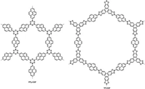
TP-COF is the firstsemiconducting COF that consists oftriphenylene and pyrene. TP-COF was synthesized by a condensation of pyrene-2,7-diboronicacid (PDBA) and 2,3,6,7,10,11l-hexahydroxytriphenylene (HHTP) under solvothermal conditions. The electrical conductivity of TP-COF was measured using a two-probe method and theI-V profile of TP-COF in air at 25 0C is linear curve. The electric current is 4.3 nA at 2V bias voltage while the mixture of HHTP and PDBA (2/3) is only 79 pA under the same condition. The electric current of TP-COF could be on-off switched repeatedly several times without significant deterioration. When TP-COF was oxidized by I2, the electric current could be significantly increased at the same bias, which suggests that TP-COF shows a typical p-type semiconductor character.49
PPy-COF was the first example ofboroxine-linked p-type COF. PPy-COF could be easily synthesized by the self-condensation of pyrenediboronic acid (PDBA) in 1,4-dioxnae/mesitylene (1/1 v/v, 5 mL) mixture with 88% yield. When comparing
Chapter 1. General Introduction
–––––––––––––––––––––––––––––––––––––––––––––––––––––––––––––––––––––––––––––––
current at the same voltage with identical conditions. Upon oxidized with iodine to generate holes, the electrical current could be further increased.50
Figure 9.Structure representation of π-electronic and photoconductive COFs.
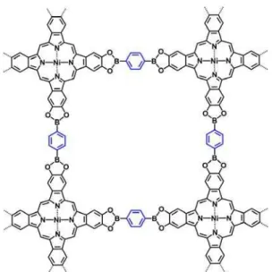
For charge carrier transport, the planarity and large π-system of organic molecular units are very important. Integrationof large planar π-systems such as phthalocyanineto COFs facilitates charge carrier transport. NiPc COF is one typical example, which was synthesized by the condensation reaction of (2,3,9,10,16,17,23,24-octahydroxyphthalocyaninato)nickel(II), [(OH)8PcNi] and 1,4-benzenediboronic acid (BDBA) under solvothermal conditions.By using FP-TRMC measurements, the minimum hole mobility of NiPc COF was evaluated to be as high as 1.3 cm2V–1s–1.51
Figure 10.Structure representation of NiPc COF.
Improving the conjugated degree of COFswith fully fusedskeletons, CS-COF,is key to electrical conductivity and carrier mobility. CS-COF was synthesized through the condensation of C3-symmetric triphenylene hexamine (TPHA) and C2-symmetric tert-butylpyrenetetraone (PT) under solvothermal conditions. Through the flash photolysis time-resolved microwave conductivity measurements, the holemobility of CS-COF was estimated to be as high as 4.2 cm2V–1s–1.30
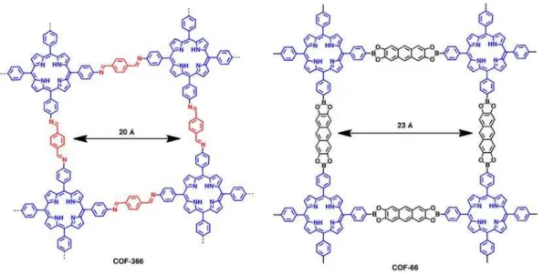
As for imine-based COFs, COF-366 shows a typical p-type semiconductor behavior with outstanding hole mobility and high electrical conductivity. COF-366 was synthesized through the condensation of tetra(p-amino-phenyl)porphyrin and terephthaldehyde with solvothermal conditions (Figure 11). To verify the well-defined sheet structures together with the layers alignment of COFs benefit the flow of carriers, the electrical conductivity of COF-366 was measured across a gap of 2 um between two Au electrodes. COF-366 and COF-66 showed almost linear I-V curve in air at 25 0C. Especially for COF-366, the electric current was up to 0.75 nA at 0.2V. This result proved both of COF-366 and COF-66 were electric semiconducting. Both COF-366 and COF-66 were p-type semiconductors and the one-dimensional hole mobilities were 8.1 cm2V–1s–1for COF-366 and 3.0 cm2V–1s–1for COF-66.52
Chapter 1. General Introduction
–––––––––––––––––––––––––––––––––––––––––––––––––––––––––––––––––––––––––––––––
Figure 11. Schematic representation of the structure of COF-366 and COF-66.
It is well known that organic molecular tetrathiafulvalene (TTF) is a typical electron donor with high hole mobilities measured by OFET devices.By using TTF as monomers, TTF-COF exhibited high electric conductivity. The stacked TTF columns sever as conductive pathways and the open nanochannels allow doping to form charge-transfer complex. Through the condensation reaction of TTF tetraaldehyde and 1,4-diaminobenzene in a mixture of aqueous acetic acid (3 M)/dioxane/mesitylene (1/5/5 v/v/v) at 120 °C for 3 days, TTF-COF was synthesized with isolated yield 52%.TTF-COF thin film with average thickness around 150 nm was fabricated by in situ film growth deposition method.Based on the conductivity measurements of TTF-COF thin films grown on Si/SiO2 (300 nm) substrate, the I-V curve of TTF-COF exhibited a linear response, with a conductivity of 1.2 × 10⁻⁴ Sm–1. Doping the TTF-COF thin film with I2 vapor could further increase the conductivity up to1.0 × 10–3 Sm–1. The UV-vis-near IR (NIR) spectra of TTF-COF thin films appeared a broad, low intensity pear in the NIR region after exposed to I2 vapor, which was attributed to the mixed-valence TTF species formed between TTF and TTF radical cation.53
condensation of terephthalaldehyde with [H2N]6HPB and [H2N]6HBC under solvothermal conditions. Based on the FP-TRMC measurements, the intrinsic hole mobility of HBC-COF was as high as 0.7 cm2V–1s–1.34
1.1.3.4.2n-Type Semiconducting COFs
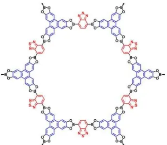
The first n-type COF was 2D-NiPc-BTDA that was synthesized by a condensation reaction of (2,3,9,10,16,17,23,24-octahydroxyphthalocyaninato)nickel(II) ([OH]8PcNi) and 1,4-benzothiadiazole diboronic acid (BTDADA) under solvothermal conditions. The electron-withdrawing building block BTDADA in the AA stacking arrangement of 2D Phthalocyanine sheets could provide an electron transport pathway. The electron mobility of 2D-NiPc-BTDA COF was as high as 0.6 cm2V–1s–1.54
Figure 12.Structure representation of 2D-NiPc-BTDA COF.
1.1.3.4.3Ambipolar Semiconducting COFs
2D D-A COF was one of the first ambipolar semiconducting COFs. It was synthesized through the condensation of 2,3,6,7,10,11-hexahydroxytriphenylene (HHTP) and 1,4-benzothiadiazole diboronic acid (BTDADA) under solvothermal
Chapter 1. General Introduction
–––––––––––––––––––––––––––––––––––––––––––––––––––––––––––––––––––––––––––––––
conditions. 2D D-A COF generated periodic and unidirectional D-on-D and A-on-A columnar arrays in an extended and layered crystalline framework. The layer aligned periodic independent pathways allow for ambipolar electron and hole conductions and vertically ordered p-n heterojunctions with a broad D-A interface. Through FP-TRMC measurements, the hole and electron mobilities of the 2D D-A COF was 0.01 and 0.04 cm2V–1s–1, respectively. The 2D D-A COF consists of segregated D-on-D and A-on-A columns thatprovide pathways for the motions of holes and electrons and leads to typical ambipolar semiconductor behavior.55
Figure 13.Structure representation of 2D D-A COF.
1.1.3.5 Photoluminescence
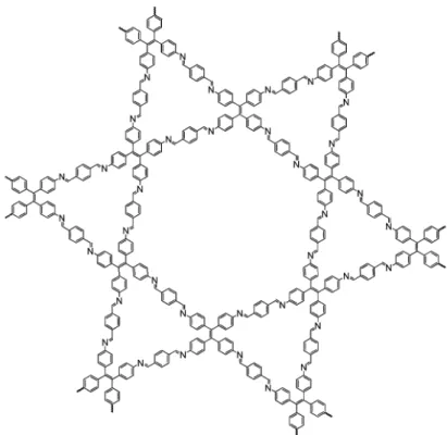
TP-COF is the first example of photoluminescence COF. The belts of TP-COFhad a blue luminescence and exhibited an emission signal at 474 nm when excited at 376 or 417 nm.49PPy-COF is also blue-luminescent COF when exposed to visible light. When exciting at 414 nm, PPy-COF showed light emitting at 484 nm, while the monomer exhibited luminescence at 421 nm.50 COF-LZU8 is a thioether-based hydrazone-linked COF. When excited at 390 nm, COF-LZU8 showed
relative low quantum yield of 0.8% when excited at 366 nm. The difference in the luminescent lies on the extended conjugation framework in COF-LZU8. In the meantime, COF-LZU8 could keep fluorescence property even in common organic solvents. Together with the thioether groups from the COF structure, COF-LZU8 could be used for detection and removal of the toxic Hg2+.56 3D-Py-COF is the first example of fluorescent 3D COFs. 3D-Py-COF was synthesized through the condensation of 1,3,6,8-tetrakis(4-formylphenyl)pyrene (TFPPy) and tetra(p-aminophenyl)methane (TAPM)under solvothermal conditions. Due to the isolated pyrene units in the 3D COF network, 3D-Py-COF showed an intense yellow green luminescence. When excited at 408 nm, the suspension of 3D-Py-COF in DMF emitted at 484 nm. The fluorescence of 3D-Py-COF could be effectively quenched when picric acid was added into the suspension. The result demonstrated the chemosensing behavior of 3D-py-COF.57
1.1.3.6Photocatalytic Hydrogen Evolution
TFPT-COF is the first example of COFsthat exhibit photocatalytic activity for hydrogen evolution under visible light irradiation. TFPT-COF was synthesized through the condensation of 1,3,5-tris-(4-formyl-phenyl)triazine (TFPT) and 2,5-diethoxy-terephthalohydrazide (DETH) building blocks. Visible light induced hydrogen evolution of TFPT-COF was measured under standardized conditions in the presence of the PRC Pt, using sodium ascorbate as sacrificial electron donor. TFPT-COF exhibited continuous and stable hydrogen evolution of 230 μmol h–1 g–1, whereas the monomer TFPT did not show any photocatalytic activity under the same conditions. Even after three cycles, the hydrogen evolution amount did not change. When utilizing a 10 vol% aqueous triethanolamine (TEOA) solution as sacrificial donor, the hydrogen evolution rate could be further increased up to 1970 μmol h–1 g–1, corresponding to a quantum efficiency of 2.2%. This framework is competitive with the best non-metal photocatalysts for hydrogen production.58
Chapter 1. General Introduction
–––––––––––––––––––––––––––––––––––––––––––––––––––––––––––––––––––––––––––––––
Figure 14.Structure representation of TFPT-COF.
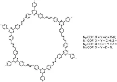
Another visible light induced hydrogen evolution result of COFs are Nx-COFs. Nx-COFs were synthesized by a condensation between the corresponding trialdehydes with hydrazine under solvothermal conditions. A progressive substitution of alternate carbons in the central aryl ring of thetriphenylarylbackbone by nitrogen atomsleads to a change in the electronic and steric properties of thecentral ring, that is, N=0 (phenyl), N=1 (pyridyl), N=2(pyrimidyl) and N=3 (triazine). The Nx–COFs exhibited fourfold increase in hydrogen production with gradual substitution of C-H by N in the central aryl ring of the COF. The final hydrogen evolution rates of N0, N1, N2 and N3–COF were about 23, 90, 438 and 1,703 μmol h–1 g–1, respectively. The result of N3-COF was competitive with g–C3N4(840μmol h–1 g–1) orcrystalline poly(triazine imide) (864 μmol h–1 g–1).59
Figure 15.Structure representation of Nx-COF.
1.2 Scope of This Thesis
As described above, covalent organic frameworks (COFs) are a new class of crystalline porous polymer that possesses periodic structure and nanometer-sized open channels. Owing to the ordered two-dimensional layeredstructure, COFs have great potential as organic semiconductors and have shown their functions in energy transfer, electric conductivity, photoconductivity, photo-induce light emitting, organic field effect transistor and organic solar cells. However,COFs reported to date have limited stability and are still poor in optoelectronic properties, which preclude their practical implementations.To challenge these fundamental issues of the field, it is necessary to explore new strategies for the design and synthesis of COFs. This background motivated me to enter into the field of COFs and to concentrate myself on exploring novel COFs with unprecedented structures and functions.
Through the three-year study, the author explored new strategy for designing and synthesizing a series of novel light-emitting and semiconducting COFs. In chapter 1, the state-of-the-art researches in the COFs field were comprehensively reviewed.
Chapter 1. General Introduction
–––––––––––––––––––––––––––––––––––––––––––––––––––––––––––––––––––––––––––––––
Scheme 1. Schematic representation for the synthesis of HHTP-MIDA-COF with triphenylene donor as vertices and isoindigo acceptor as linkers.
In chapter 2, the author describes the design and functions of a novel semiconducting COF by integrating isoindigo unitsinto the COF skeletonto construct ordered structure with strong electron deficient and high electron mobility. These isoindigo-based COFs exhibited greatly enhanced electron mobility, whereas the stacked isoindigoπ-columns provide pre-organized pathways for carrier transport.This design strategy offers a newway to ambipolar semiconducting COFs (Scheme 1).
In chapter 3, the author describes a new strategy for designing highly emissive COFs by integrating aggregation-induced emission (AIE) mechanism to the skeletons.The integration of AIE-active units into the polygon vertices yields crystalline porous COFs with periodic π-stacked columnar AIE arrays. These columnar AIE π-arrays dominate the luminescence of the COFs, achieve exceptional quantum yield via a synergistic structural locking effect of intralayer covalent bonding and interlayer noncovalent π-π interactions to prohibit the rotation induced excitation-energy dissipation (Scheme 2). Highly luminescent covalent organic frameworks are rarely achieved because of the aggregation-caused quenchingof π-π stacked layers. Therefore, this strategy breaks through the ACQ-based mechanistic limitations of COFs and opens a way to explore highly emissive COF materials.Notably, thesehighly emissive COFsexhibitexceptional activity in sensing ammonia gas down to sub ppm level. Such a high sensitivity originates from the supramolecular self-assembly driven by Lewis acid-base interactions between boron atoms of the COFs and nitrogen atom of ammonia.
Scheme 3. Schematic representation for the synthesis of sp2c-COF with TFPPy as
Chapter 1. General Introduction
–––––––––––––––––––––––––––––––––––––––––––––––––––––––––––––––––––––––––––––––
In chapter 4, the author developsthe C=C bond formation reactions for the design and synthesis of COFs by exploring Knoevenagel polycondensation reaction under solvothermal conditions and discovers π-conjugated, fully sp2-carbon COFs (Scheme 3). Thesesp2-carbon COFs were synthesized in high yield, exhibitedextended π-conjugation in the 2D layers and are redox active with a low bandgap. These sp2-carbon COFs exhibitedunique semiconducting properties and extremely high spin density upon chemical doping. These COFs offer a new platform for developing novel organic spin and magnetic materials based on ordered framework structures.
In chapter 5, the author presents the light-driven water splitting for H2 evolution by developingsp2-carbon COFs as photocatalysts (Scheme 4). These COFs exhibited exceptional activity in producing H2 upon irradiation with visible light. The efficiency is the best one among COFs and other porous materials reported to date. When comparing with amorphous conjugated polymers with the same chemical structure, the crystalline sp2-carbon COFsexhibitedefficiency that is much superiorto the amorphous analogues. These results demonstrate the importance of the crystalline structure of sp2-carbon COF in water splitting and hydrogen evolution, in which the ordered π-structure prevents exciton recombination and enables efficient separation of excitons into electrons and holes.
Scheme 4. Schematic representation for the synthesis of sp2c-COF-TGthrough three components polycondensation of TFPPy, PDAN and 3-ethylrhodanine.
Chapter 1. General Introduction
–––––––––––––––––––––––––––––––––––––––––––––––––––––––––––––––––––––––––––––––
Inchapter 6, the author demonstrates the light-emitting functions of a series of sp2-carbon COFs (Scheme 5). The phenylenevinylene-based AIE skeletonsendow these COFs with bright orange-red luminescence andhigh quantum efficiency.Eitherdispersed solutions in common solvents systems or solid powder exhibitedprominent light emitting property. Significantly, these COFs are highly stable in water, organic solvents,and acidic andbasic solutions. These COFskept theircrystalline structures even upon exposure to air for more than a half year.Together with ordered layer and porous structures, theseluminescent COFsserve asnovel chemo- and biosensors.
Scheme 5. Schematic representation for the synthesis of sp2c-COF-2 with TFPPy as vertices and BPDAN as linkers.
In summary, through the three-year study, the author has developed a new strategy for the design and synthesis of a series of highly emissive and semiconducting COFs. Especially the discovery of sp2-carbon COFs opens a new molecular platform based on two-dimensional organic materials for exploring novel
1.3 References
[1] Côté, A. P.; Benin, A. I.; Ockwig, N. W.; O’Keeffe, M.; Matzger, A. J.; Yaghi, O. M. Science2005, 310, 1166.
[2] Feng, X.; Ding, X.; Jiang, D. Chem. Soc. Rev. 2012, 41, 6010.
[3] Waller, P. J.; Gandara, F.; Yaghi, O. M. Acc. Chem. Res. 2015, 48, 3053. [4] Huang, N.; Wang, P.; Jiang, D. Nat. Rev. Mater. 2016, 1, 16068.
[5] Rowan, S. J.; Cantrill, S. J.; Cousins, G. R. L.; Sanders, J. K. M.; Stoddart, J. F. Angew. Chem., Int. Ed., 2002, 41, 898.
[6] Uribe-Romo, F. J.; Doonan, C. J.; Furukawa, H.; Oisaki, K.; Yaghi, O. M. J. Am. Chem. Soc.2011, 133, 11478.
[7] Zeng, Y.; Zou, R.; Luo, Z.; Zhang, H.; Yao, X.; Ma, X.; Zou, R.; Zhao, Y. J. Am. Chem. Soc.2015, 137, 1020.
[8] Xu, H.; Tao, S.; Jiang, D. Nat. Mater.2016, 15, 722.
[9] Uribe-Romo, F. J.; Doonan, C. J.; Furukawa, H.; Oisaki, K.; Yaghi, O. M. J. Am. Chem. Soc.2011, 133, 11478.
[10] Chen, X.; Addicoat, M.; Jin, E.; Xu, H.; Hayashi, T.; Xu, F.; Huang, N.; Irle, S.; Jiang, D. Sci. Rep. 2015, 5, 14650.
[11] Dalapati, S.; Jin, S.; Gao, J.; Xu, Y.; Nagai, A.; Jiang, D. J. Am. Chem. Soc.2013, 135, 17310.
[12] Guo, J.; Xu, Y.; Jin, S.; Chen, L.; Kaji, T.; Honsho, Y.; Addicoat, M. A.; Kim, J.; Saeki, A.; Ihee, H.; Seki, S.; Irle, S.; Hiramoto, M.; Gao, J.; Jiang, D. Nat. Commun.2013, 4, 2736.
[13] Fang, Q.; Zhuang, Z.; Gu, S.; Kaspar, R. B.; Zheng, J.; Wang, J.; Qiu, S.; Yan, Y. Nat. Commun. 2014, 5, 4503.
[14] Fang, Q.; Wang, J.; Gu, S.; Kaspar, R. B.; Zhuang, Z.; Zheng, J.; Guo, H.; Qiu, S.; Yan, Y. J. Am. Chem. Soc.2015, 137, 8352.
[15] Kuhn, P.; Antonietti, M.; Thomas, A. Angew. Chem., Int. Ed.2008, 47, 3450. [16] Bojdys, M. J.; Jeromenok, J.; Thomas, A.; Antonietti, M. Adv. Mater. 2010, 22,
Chapter 1. General Introduction
–––––––––––––––––––––––––––––––––––––––––––––––––––––––––––––––––––––––––––––––
[17] Nagai, A.; Chen, X.; Feng, X.; Ding, X.; Guo, Z.; Jiang, D. Angew. Chem., Int. Ed.2013, 52, 3770.
[18] Du, Y.; Yang, H.; Whiteley, J. M.; Wan, S.; Jin, Y.; Lee, S.-H.; Zhang, W. Angew. Chem., Int. Ed.2016, 55, 1737.
[19] Colson, J. W.; Dichtel, W. R. Nat. Chem. 2013, 5, 453.
[20] Katekomol, P.; Roeser, J.; Bojdys, M.; Weber, J.; Thomas, A. Chem. Mater., 2013, 25, 1542.
[21] Campbell, N. L.; Clowes, R.; Ritchie, L. K.; Cooper, A. I. Chem. Mater. 2009, 21, 204.
[22] Dogru, M.; Sonnauer, A.; Gavryushin, A.; Knochel, P.; Bein, T. Chem. Commun., 2011, 47, 1707.
[23] Ren, S.; Bojdys, M. J.; Dawson, R.; Laybourn, A.; Khimyak, Y. Z.; Adams, D. J.; Cooper, A. I. Adv. Mater. 2012, 24, 2357.
[24] Biswal, B. P; Chandra, S.; Kandambeth, S; Lukose B.; Heine, T.; Banerjee, R. J. Am. Chem. Soc.2013, 135, 5328.
[25] Colson, J. W.; Woll, A. R.; Mukherjee, A.; Levendorf, M. P.; Spitler, E. L.; Shields, V. B.; Spencer, M. G.; Park, J.; Dichtel, W. R. Science2011, 332, 228. [26] Zwaneveld, N. A. A.; Pawlak, R. m.; Abel, M. ; Catalin, D.; Gigmes, D.; Bertin,
D.; Porte, L. J. Am. Chem. Soc.2008, 130, 6678.
[27] Kandambeth, S.; Mallick, A.; Lukose, B.; Mane, M. V.; Heine, T.; Banerjee, R. J. Am. Chem. Soc. 2012, 134, 19524.
[28] Huang, N.; Ding, X.; Kim, J.; Ihee, H.; Jiang, D. Angew. Chem., Int. Ed.2015, 54, 8704.
[29] Dogru, M.; Handloser, M.; Auras, F.; Kunz, T.; Medina, D.; Hartschuh, A.; Knochel, P.; Bein, T. Angew. Chem., Int. Ed.2013, 52, 2920.
[30] Chen, X.; Addicoat, M.; Jin, E. Q.; Zhai, L. P.; Xu, H.; Huang, N.; Guo, Z. Q.; Liu, L. L.; Irle, S.; Jiang, D. L. J. Am. Chem. Soc.2015, 137, 3241.
[32] Ding, X.; Feng, X.; Saeki, A.; Seki, S.; Nagai, A.; Jiang, D. Chem. Commun. 2012, 48, 8952.
[33] Chen, X.; Huang, N.; Gao, J.; Xu, H.; Xu, F.; Jiang, D. Chem. Commun. 2014, 50, 6161.
[34] Dalapati, S.; Addicoat, M.; Jin, S.; Sakurai, T.; Gao, J.; Xu, H.; Irle, S.; Seki, S.; Jiang, D. Nat. Commun. 2015, 6, 7786.
[35] Zhou, T.-Y.; Xu, S.-Q.; Wen, Q.; Pang, Z.-F.; Zhao, X. J. Am. Chem. Soc.2014, 136, 15885.
[36] Pang, Z. F.; Xu, S. Q.; Zhou, T. Y.; Liang, R. R.; Zhan, T. G.; Zhao, X. J. Am. Chem. Soc.2016, 138, 4710.
[37] Zhu, Y.; Wan, S.; Jin, Y.; Zhang, W. J. Am. Chem. Soc. 2015, 137, 13772.
[38] Feng, X.; Liu, L.; Honsho, Y.; Saeki, A.; Seki, S.; Irle, S.; Dong, Y.; Nagai, A.; Jiang, D. Angew. Chem., Int. Ed. 2012, 51, 2618.
[39] Lukose, B.; Kuc, A.; Heine, T. Chem. Eur. J.2011, 17, 2388.
[40] Yu, S.-B.; Lyu, H.; Tian, J.; Wang, H.; Zhang, D.-W.; Liu, Y.; Li, Z.-T. Poly. Chem.2016, 7, 3392.
[41] Shan, M.; Seoane, B.; Rozhko, E.; Dikhtiarenko, A.; Clet, G.; Kapteijn, F.; Gascon, J. Chem. Eur. J. 2016, 22, 14467.
[42] Li, Z.; Feng, X.; Zou, Y.; Zhang, Y.; Xia, H.; Liu, X.; Mu, Y. Chem. Commun.2014, 50, 13825.
[43] Zeng, Y.; Zou, R.; Zhao, Y. Adv. Mater.2016, 28, 2855.
[44] Alahakoon, S. B.; Thompson, C. M.; Nguyen, A. X.; Occhialini, G.; McCandless, G. T.; Smaldone, R. A. Chem. Commun.2016, 52, 2843.
[45] Ding, S. Y.; Gao, J.; Wang, Q.; Zhang, Y.; Song, W.; Su, C.; Wang, W. J. Am. Chem. Soc. 2011, 133, 19816.
[46] Xu, H.; Chen, X.; Gao, J.; Lin, J.; Addicoat, M.; Irle, S.; Jiang, D. Chem. Commun. 2014, 50, 1292.
[47] Xu, H.; Gao, J.; Jiang, D. L. Nat. Chem.2015, 7, 905.
Chapter 1. General Introduction
–––––––––––––––––––––––––––––––––––––––––––––––––––––––––––––––––––––––––––––––
[48] Calik, M.; Auras, F.; Salonen, L. M.; Bader, K.; Grill, I.; Handloser, M.; Medina, D. D.; Dogru, M.; Löbermann, F.; Trauner, D.; Hartschuh, A.; Bein, T. J. Am. Chem. Soc.2014, 136, 17802.
[49] Wan, S.; Guo, J.; Kim, J.; Ihee, H.; Jiang, D. Angew. Chem., Int. Ed.2008, 47, 8826.
[50] Wan, S.; Guo, J.; Kim, J.; Ihee, H.; Jiang, D. Angew. Chem., Int. Ed. 2009, 48, 5439.
[51] Ding, X.; Guo, J.; Feng, X.; Honsho, Y.; Seki, S.; Maitarad, P.; Saeki, A.; Nagase, S.; Jiang, D. Angew. Chem., Int. Ed.2011, 50, 1289.
[52] Wan, S.; Gándara, F.; Asano, A.; Furukawa, H.; Saeki, A.; Dey, S. K.; Liao, L.; Ambrogio, M. W.; Botros, Y. Y.; Duan, X.; Seki, S.; Stoddart, J. F.; Yaghi, O. M. Chem. Mater.2011, 23, 4094.
[53] Cai, S. L.; Zhang, Y. B.; Pun, A. B.; He, B.; Yang, J. H.; Toma, F. M.; Sharp, I. D.; Yaghi, O. M.; Fan, J.; Zheng, S. R.; Zhang, W. G.; Liu, Y. Chem. Sci.2014, 5, 4693.
[54] Ding, X. S.; Chen, L.; Honsho, Y.; Feng, X.; Saenpawang, O.; Guo, J. D.; Saeki, A.; Seki, S.; Irle, S.; Nagase, S.; Parasuk, V.; Jiang, D. L. J. Am. Chem. Soc.2011, 133, 14510.
[55] Feng, X.; Chen, L.; Honsho, Y.; Saengsawang, O.; Liu, L.; Wang, L.; Saeki, A.; Irle, S.; Seki, S.; Dong, Y.; Jiang, D. Adv. Mater. 2012, 24, 3026.
[56] Ding, S. Y.; Dong, M.; Wang, Y. W.; Chen, Y. T.; Wang, H. Z.; Su, C. Y.; Wang, W. J. Am. Chem. Soc.2016, 138, 3031
[57] Lin, G.; Ding, H.; Yuan, D.; Wang, B.; Wang, C. J. Am. Chem. Soc.2016, 138, 3302.
[58] Stegbauer, L.; Schwinghammer, K.; Lotsch, B. V. Chem. Sci.2014, 5, 2789. [59] Vyas, V. S.; Haase, F.; Stegbauer, L.; Savasci, G.; Podjaski, F.; Ochsenfeld, C.;
Lotsch, B. V. Nat. Commun.2015, 6, 8508.
Chapter 2
Isoindigo-Based Covalent Organic
Frameworks and Semiconducting Functions
Submitted
Enquan Jin,Wakana Matsuda, Mattew A. Addicoat, Hong Xu, Tsuneaki Sakurai, Shu Seki, Thomas Heine and Donglin Jiang
Chapter 2. Isoindigo-Based Covalent Organic Frameworks and Semiconducting Functions ––––––––––––––––––––––––––––––––––––––––––––––––––––––––––––––––––––––––––––––––––––––––––––
Abstract
Organization of well-defined electron donor-acceptor structures is crucial for organic electronics. Especially how to create a structure that enables the balanced transport of both charge carriers, i.e., hole and electron, is still a synthetic challenge. Here we report that integrating strong electron acceptors into covalent organic frameworks (COFs) by using non-conjugated linkages to spatially and electronically block the donor-acceptor interactions, holds the key to balanced high-rate hole and electron conductions. Topology-directed polycondensation of triphenylene vertices as electron donor and isoindigo linkers as electron acceptor generates a new donor-acceptor-based hexagonal COF. The resulting COF consists of isolated donor-on-donor and acceptor-on-acceptor columnar π-arrays, rendering themable to function as independent pathways for achieving balanced yet high-rate hole and electron conductions.
2.1 Introduction
Two-dimensional (2D) COFs possess ordered π-columnar structures and nanochannels and have many shown a diversity of potential applications such as gas adsorption, catalysis and energy storage.1-21 By virtue of their ordered π-columnar arrays, COFs have emerged as a unique platform for designing semiconducting materials. The aligned π-columns serve as a pathway for charge carrier transport. Based on molecular design of π-building blocks, a series of semiconducting COFs with different structures have been continuously developed.22-25 By introducing electron donor and acceptor units to the knots and linkers of the polygon backbones, the stacked π-columns could offer pathways for electron or hole conductions depending on their structures. These highly ordered π-structures arehardly achieved by traditional organic semiconducting materials.26-30 Although donor-acceptor COFs with independent donor and acceptor columns have been designed and synthesized, their carrier mobilities of hole and electron are unbalanced; especially the electron mobility needs to be greatly improved. Moreover, the strategy for achieving a balanced electron and hole conducting materials remains to be disclosed.
As a electron deficient organic building block, isoindigo unit has been widely used in organic semiconducting fields, such as organic solar cells and organic field-effect transistors.31-32 For example, introducing isoindigo units to conjugated polymer back bones could lower down their bandgap and broaden their absorption band.33-36 In contrast to single crystals of isoindigo that have ordered structure and allow for high-rate electron conduction, the electron mobility of isoindigo-based conjugated polymers is extremely low (the highest one is 3.7 × 10⁻⁷ cm2 V–1 s–1).34 These polymers usually aggregate to yield disordered assembly of polymer chains and eventually cause stacked donor-on-acceptor architectures that block the formation of ordered isoindigo-on-isoindigo structures.37-38 This aggregation tendency greatly limits the possibility of using isoindigo units for the synthesis of n-type or ambipolar materials, which are however, useful in organic semiconducting field.
Chapter 2. Isoindigo-Based Covalent Organic Frameworks and Semiconducting Functions ––––––––––––––––––––––––––––––––––––––––––––––––––––––––––––––––––––––––––––––––––––––––––––
To solve these problems, I introduced isoindigo building blocks as acceptor to the COF skeletons that enable ordered alignment of isoindigo units and employed boronate ester linkages that spatially and electronically block the electron donor-acceptor interactions, by which the donor and acceptor π-columns in the COFs become independent for charge carrier conduction.
2.2 Results and Discussions
2.2.1 Synthesis and Structural Characterizations
I designed C3-symmetric 2,3,6,7,10,11-hexahydroxytriphenylene (HHTP) as electron rich knots and C2-symmetric 6,6’-N,N’-(2-methyl)-isoindigo diboronic acid (MIDA) as strong electron deficient edges for the synthesis of a donor-acceptor COF (HHTP-MIDA-COF) under solvothermal conditions. HHTP-MIDA-COF was prepared as dark red crystallites.
Elemental analysis showed that C, H and N contents were nearly close to the calculated values. Field-emission scanning microscopy revealed that HHTP-MIDA-COF exhibited a micrometer-scale sheet-shape morphology (Figure 1). Thermogravimetric analysis suggested that HHTP-MIDA-COF is stable up to 400 °C under nitrogen (Figure 2).
Figure 2. Thermogravimetric analysis curve of HHTP-MIDA-COF. 2.2.2 Electronic Property
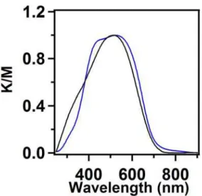
The MIDA monomer is red colorized whereas the HHTP monomer is white. After polymerization, the product HHTP-MIDA-COF is also red colorized. Electronic absorption spectroscopy demonstrated that HHTP-MIDA-COF has a broad absorption band centered at 520 nm, while the MIDA monomer has an absorption band centered at 515 nm (Figure 3).
Figure 3. Solid-state electronic absorption spectra of HHTP-MIDA-COF (blue curve) and MIDA units (black curve).
Compared to TP-Por COF (HOMO = –5.42 eV), HHTP-MIDA-COF achieved
Chapter 2. Isoindigo-Based Covalent Organic Frameworks and Semiconducting Functions ––––––––––––––––––––––––––––––––––––––––––––––––––––––––––––––––––––––––––––––––––––––––––––
HHTP-MIDA-COF exhibits highly ordered periodic structure with discrete hole and electron pathways through the Donor-on-Donor and Acceptor-on-Acceptor stacking alignment.
To disclose the conducting nature of HHTP-MIDA-COF, I introduced the electrode less flash-photolysis time-resolved microwave conductivity (FP-TRMC) method. With laser pulse irradiation of HHTP-MIDA-COF under a rapidly oscillating electric field, FP-TRMC could measure the inherent charge carrier mobility of COFs. Under Ar atmosphere, FP-TRMC measurements could evaluate the total carrier mobilities (Σμtotal) of HHTP-MIDA-COF, including both electrons and holes. Then I measured the hole mobility by using SF6 atmosphere, because electrons could be trapped by SF6. Based on these results, the intrinsic carrier mobilities of holes and electrons were evaluated.
When excited HHTP-MIDA-COF with a 355 nm pulsed laser at a photon density of 4.6× 10¹⁵ photon cm–2 under Ar atmosphere, the ϕΣμ value was up to 2.4 × 10⁻⁵ cm2 V–1 s–1 (Figure 5). To evaluate the hole mobility and electron mobility, HHTP-MIDA-COF was further excited with a 355 nm pulsed laser under Ar atmosphere and SF6 atmosphere. The results indicate that the ϕΣμ value ratio of holes and electrons is about 3/2. HHTP-MIDA-COF is ambipolar semiconductor in which the triphenylene π-columns form a pathway for hole transport and the ordered isoindigo π-columns build a pathway for electron transport.
Figure 5. (a) FP-TRMC profile of HHTP-MIDA-COF under Ar atmosphere. (b) FP-TRMC profile of HHTP-MIDA-COF under SF6 atmosphere (red curve). (c) Photocurrent generation of spin coated HHTP-MIDA-COF on a comb-type gold electrode device (electrode gap = 5 μm) at different bias voltages (1, 2, 4, 7 and 10 V). (d) I–V curve of HHTP-MIDA-COF on the comb-type gold electrode device.
2.3 Conclusion
In summary, I have developed a strategy for construction of balanced ambipolar yet high-rate conducting COFs. The newly designed HHTP-MIDA-COF with triphenylene donor as knots and isoindigo acceptor as linkers constitutes isolated π-columns as independent pathways for the conductions of holes and electrons. Incorporating isoindigo units to the boronate ester-linked COF skeleton successfully maintains the high electron mobility of isoindigo units, which could not be achieved with isoindigo-based 1D conjugated polymers. The well balanced ambipolar HHTP-MIDA-COF with high hole mobility and electron mobility, could further be extended to optoelectronic application and organic field effect transistor.
Chapter 2. Isoindigo-Based Covalent Organic Frameworks and Semiconducting Functions ––––––––––––––––––––––––––––––––––––––––––––––––––––––––––––––––––––––––––––––––––––––––––––
2.4 Experimental Sections 2.4.1 Methods
1,3,5-Trimethylbenzene (Mesitylene), tetrahydrofuran (THF), methanol (MeOH), diethyl ether, CHCl3, potassium acetate (KOAc), potassium carbonate were purchased from Kanto Chemicals. KOAc was further heated at 120 °C for 6 h to remove the water content. Potassium bromide crystal block (KBr), anhydrous tetrahydrofuran (THF), anhydrous acetone, anhydrous 1,4-dioxane, hydrochloric acid (HCl), sodium periodate and dimethylsulfoxide-d6 (d6-DMSO) were purchased from Wako chemicals, Japan. Anhydrous solvents were further treated with activated molecular sieve (4 Å). Iodomethane, Chloroform-d3 (CDCl3), [1,1’-Bis(diphenyl-phosphino)-ferrocene] palladium (II) Dichloride dichloromethane adduct and bis(pinacolato)diboron were purchased from Tokyo Kasai Co. (TCI), Japan. 6,6’-N,N’-(2-methyl)-isoindigo diboronic acid unit was synthesized according to modified literature method.
1H NMR spectra were measured on JEOL models JNM-LA400 NMR spectrometer. Fourier transform infrared (FT-IR) spectra were recorded on a JASCO model FT-IR-6100 infrared spectrometer. Elemental analysis was performed on a Yanako CHN CORDER MT-6 elemental analyzer. Field-emission scanning electron microscopy (FE-SEM) was performed on a JEOL model JSM-6700 and/or Hitachi high technologies (SU-6600) operating at an accelerating voltage of 5.0 kV. The sample was prepared by drop-casting anhydrous acetone suspension onto mica substrate and then coated with gold. X-ray diffraction (XRD) data were recorded on a Rigaku model RINT Ultima III diffractometer by placing powder on glass substrate, from 2θ = 1.5° up to 40° with 0.02° increment. Thermal gravimetric analysis (TGA) was performed on a METTLER TOLEDO instrument (model TGA/SDTA851e). UV-Vis spectra were recorded on a JASCO model V-670 spectrometer with the samples grinded KBr. Fluorescence spectra were recorded on a JASCO model FP-6600 spectrofluorometer and fluorescence quantum yield was measured with
Hamamatsu model compact fluorescence lifetime spectrometer C11367 (Quantaurus-Tau) that contains an light-emitting diode (LED) pulsed light source, monochromator, PMT (photo multiplier tube), iris (aperture) for adjusting light level, and filter for cutting excitation light. The samples were irradiated by light source from internal LED at 365 nm. Fluorescence microscope images were taken from Olympus BX51 by placing powder on glass slide or dropcast by anhydrous acetone dispersed COF samples with UV (330-380 nm) light excitations.
Nitrogen sorption isotherms were measured at 77 K with a Micromeritics Instrument Corporation model 3Flex surface characterization analyzer for small particle. Before measurement, the samples were degassed in vacuum at room temperature for 24 h. The Brunauer-Emmett-Teller (BET) method was utilized to calculate the specific surface areas. By using the non-local density functional theory (NLDFT) model, the pore size distribution was derived from the sorption curve.
Structures of single pore monolayers and stacked isomers (AA and AB) were built from models of the HHTP and MIDA linkers using AuToGraFS5a, and optimized using the self-consistent charge density-functional tight-binding (SCC-DFTB) method including Lennard-Jones (LJ) dispersion as implemented in the DFTB+ program package version 1.2.5b Standard DFTB parameters for X-Y element pair (X, Y = C, O, and H) interactions were employed from the mio-0-1 set6, B-Y parameters were taken from the rscc materials set. The lattice dimensions were optimized simultaneously with the geometry.
Molecular modeling and Pawley refinement were carried out using Reflex, a software package for crystal determination from XRD pattern, implemented in MS modeling version 4.4 (Accelrys Inc.). Initially, unit cell dimensions for both hexagonal lattices were taken from the DFTB calculation and the space group for hexagonal crystal system were selected as P622, respectively. We performed Pawley refinement for hexagonal lattice to optimize the lattice parameters iteratively until the RWP value converges. The pseudo–Voigt profile function was used for whole profile
Chapter 2. Isoindigo-Based Covalent Organic Frameworks and Semiconducting Functions ––––––––––––––––––––––––––––––––––––––––––––––––––––––––––––––––––––––––––––––––––––––––––––
refinement processes. A dual-pore crystal system was deduced with lattice parameter of, a = b = 37.466 Å, c = 4.45 Å, α = = 90°, and = 120° and the final Rwp and Rp
values appear as 8.32% and 6.38%, respectively. 2.4.2 Materials and Synthetic Procedures
6,6’-Dibromo-N,N’-(2-methyl)-isoindigo and 2,3,6,7,10,11-hexahydroxytriphenylene (HHTP) units were synthesized according to the literature.29,36
6,6’-Bis(4,4,5,5-tetramethyl-1,3,2-dioxaborolan-2-yl)-N,N’-(2-methyl)
isoindigo. Anhydrous 1,4-dioxane (150 mL) and 1.32 g KOAc (13.45 mmol) in a dried 250 mL two-neck roundbottle flask was Ar bubbled for 30 minutes. 6,6’-Dibromo-N,N’-(2-methyl)-isoindigo (1.00 g, 2.23 mmol), bis(pinacolato)diboron(1.25 g, 4.92 mmol), and [1,1’-Bis(diphenyl-phosphino)-ferrocene] palladium(II) dichloridedichloromethane
adduct (120 mg, 0.16 mmol) were added respectively under Ar. The mixture was degassed through three freeze-pump-thaw cycles and heated to reflux at 110 °C for 72 h and was monitored using thin-layer chromatograph. The reaction mixture was cooled to room temperature and poured into ice-cooled water. The solution was stirred for 15 minutes and filtered, washed the residue by water, methanol, diethyl ether and
dried under vacuum to yield 6,6’-Bis(4,4,5,5-tetramethyl-1,3,2-dioxaborolan-2-yl)-N,N’-(2-methyl) isoindigo solid
product 0.98g (81%). 13C NMR(CDCl3, 100 MHz, ppm) δ: 167.83, 144.52, 134.22, 129.24, 128.92, 124.14, 113.04, 84.17, 26.26, 24.88. Elemental Anal.: Calcd. for C30H36Br2N2O6: C, 66.45; H, 6.69;N, 5.17. Found: C, 64.17; H, 6.89; N, 5.33.
6,6’-N,N’-(2-methyl)-isoindigo diboronic acid. A mixture of THF/water was added with NaIO4 (1.18 g) in a 100 mL two neck round bottle flask, 6,6’-Bis(4,4,5,5-tetramethyl-1,3,2-dioxaborolan-2-yl)-N,N’-(2-methyl) isoindigo (500 mg) was added to the mixture. The reaction mixture was stirred at room temperature 30 minutes. An ice cooled HCl solution (1 M, 10 mL) was added to the reaction
collected and washed three times with water, methanol, respectively. The residue was dried under vacuum at roomtemperature for 24 h to yield 6,6’-N,N’-(2-methyl)-isoindigo diboronic acid (MIDA) as a red powder. Yield: 318 mg (91%). 13C NMR (d6-DMSO, 100 MHz, ppm) δ: 167.54, 144.72, 133.57, 128.34, 128.30, 122.79, 113.79, 26.46. Elemental Anal.: Calcd. for C18H16Br2N2O6: C, 57.20; H, 4.27;N, 7.41. Found: C, 56.93; H, 4.51; N, 7.17.
Synthesis of HHTP-MIDA-COF. A 10-mL pyrex tube was charged with HHTP (30.0 mg, 0.059mmol), MIDA (16.8 mg, 0.12 mmol). The mixture was sonicated for 30 seconds, degassed through three freeze–pump–thaw cycles, sealed undervacuum, and heated at 90 °C for 3 days. The reaction mixture was cooled to room temperatureand the dark red precipitate was collected by centrifugation. The precipitate was washed with anhydrous THF for several times, further washed with anhydrous acetone, centrifuged, and dried under vacuum at room temperature for 24 h, to yield dark red powder in 89% isolation yield. Elemental analysis for the calculated C (69.02%), H (3.07%), N (5.37%) and observed C (64.88%), H (4.63%), N (6.87%).
Chapter 2. Isoindigo-Based Covalent Organic Frameworks and Semiconducting Functions ––––––––––––––––––––––––––––––––––––––––––––––––––––––––––––––––––––––––––––––––––––––––––––
2.5 References
[1] Feng, X.; Ding, X.; Jiang, D. Chem. Soc. Rev.2012, 41, 6010.
[2] Waller, P. J.; Gándara, F.; Yaghi, O. M. Acc. Chem. Res. 2015, 48, 3053.
[3] Côté, A. P.; Benin, A. I.; Ockwig, N. W.; O'Keeffe, M.; Matzger, A. J.; Yaghi, O. M. Science2005, 310, 1166.
[4] Huang, N.; Wang, P.; Jiang, D. Nat. Rev. Mater. 2016, 1, 16068.
[5] Liu, Y. Z.; Ma, Y. H.; Zhao, Y. B.; Sun, X. X.; Gandara, F.; Furukawa, H.; Liu, Z.; Zhu, H. Y.; Zhu, C. H.; Suenaga, K.; Oleynikov, P.; Alshammari, A. S.; Zhang, X.; Terasaki, O.; Yaghi, O. M. Science2016, 351, 365.
[6] Colson, J. W.; Dichtel, W. R. Nat. Chem. 2013, 5, 453.
[7] Ascherl, L.; Sick, T.; Margraf, J. T.; Lapidus, S. H.; Calik, M.; Hettstedt, C.; Karaghiosoff, K.; Döblinger, M.; Clark, T.; Chapman, K. W.; Auras, F.; Bein, T. Nat. Chem.2016, 8, 310.
[8] Huang, N.; Zhai, L.; Coupry, D. E.; Addicoat, M. A.; Okushita, K.; Nishimura, K.; Heine, T.; Jiang, D. Nat. Commun. 2016, 7, 12325.
[9] Smith, B. J.; Dichtel, W. R. J. Am. Chem. Soc. 2014, 136, 8783. [10] Xu, H.; Gao, J.; Jiang, D. Nat. Chem.2015, 7, 905.
[11] Lin, S.; Diercks, C. S.; Zhang, Y. B.; Kornienko, N.; Nichols, E. M.; Zhao, Y. B.; Paris, A. R.; Kim, D.; Yang, P.; Yaghi, O. M.; Chang, C. J. Science2015, 349, 1208.
[12] Ding, S. Y.; Gao, J.; Wang, Q.; Zhang, Y.; Song, W. G.; Su, C. Y.; Wang, W. J. Am. Chem. Soc. 2011, 133, 19816.
[13] Fang, Q.; Zhuang, Z.; Gu, S.; Kaspar, R. B.; Zheng, J.; Wang, J.; Qiu, S.; Yan, Y. Nat. Commun. 2014, 5, 4503.
[14] Vyas, V. S.; Haase, F.; Stegbauer, L.; Savasci, G.; Podjaski, F.; Ochsenfeld, C.; Lotsch, B. V. Nat. Commun. 2015, 6, 8508.
[15] Xu, H.; Tao, S.; Jiang, D. Nat. Mater.2016, 722-727.