T he rm odyna m ic s of Furna c e T ube s – K illing Popula r
M yt hs a bout Furna c e T ube T e m pe ra t ure M e a sure m e nt
Mikael Cronholm
Cronholm Reliability Systems
ABST RACT
Over the last couple of years, I have taken a special interest in furnace tube thermography and it has turned out to be an extremely interesting and somewhat frightening application. What is frightening about it? It is a difficult application; that is true. But not for the reasons most people seem to imagine, and it is not so bad once you figure it out. It is also not that the application itself is ineffective; quite on the contrary, it has huge rewards for the furnace operator.
The scary thing is that it seems to me that the level of understanding is low among those that do it and that little development of practices, methodology and knowledge has taken place – people are still relying on old folklore from the seventies.
In this paper, I will throw myself to the wolves - deliberately and consciously! I will be the little boy who tells everyone that the emperor has no clothes. I am taking the risk of going diametrically against what “everybody knows” about furnace tube inspection and I will do it without fear. It is up to you if you want to praise me or tear me to pieces.
You will hear me say crazy things. I will tell you that the coldest part of the tube that you see is the hottest part. I will tell you that tube skin thermometers cannot be expected to ever measure the same temperature as the IR camera, other than by coincidence combined with a well balanced design. I will tell you that some mistakes that you can make, for example with emissivity, will sometimes have the total opposite effect on your measurement in a furnace than it normally has in other applications. And if you think emissivity is a big
problem with furnace tubes, your dreams will come true now, because it is really not much of a problem at all! Neither is atmosphere or RAT, reflected apparent temperature a very big issue. Is that wishful thinking? We will see what you think.
The key to understanding it all is really not in the radiation science and the IR measurement technique at all. It is difficult, I agree, but not that terrible. No, the real key is to understand the heat transfer process correctly. And that will not be too difficult either, as a matter of fact. The difficulty will be to shed old misconceptions, clear your mind from what you used to think was true, and accept to change the way you think.
This paper will certainly not drain the well of interesting subjects about furnace tube inspection. There is a lot more to be said about it, for example about procedures and methodologies, and radiation theory about atmospheric attenuation, and spectral distribution and filtering, and so on, but not in this paper…
T H ERM AL BALAN CE OF T H E FU RN ACE
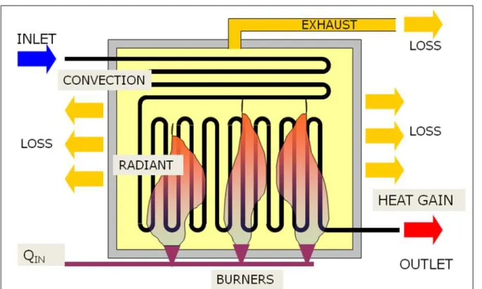
Figure 1. The thermal balance of a furnace. Energy from fuel is put in, the process fluid gains some of the heat and the rest is lost through the furnace wall and the exhaust.
Most furnaces have a radiant section at the bottom, and a convection section at the top. Those terms refer to the main heat transfer modes that take place in the respective furnace parts. Radiation is the strongest heat transfer mode, so the cooler fluid that enters the furnace will go to the convection section first, where the heat transfer is less strong. The temperature difference in the convection section between the cooler feed and the furnace exhaust gas is big enough to preheat the fluid before it goes to the radiant section where most of the heat is added. The convection section can be thought of as a kind of economizer.
T H E FU RN ACE T U BE
The furnace tube should have as little resistance as possible for heat to flow through it, and it needs to withstand high temperature and pressure, so the tubes are made of alloy steel in a great variety of
compositions. Exactly what the tubes consist of is totally unimportant to us. We only need to be concerned about the actual surface of the tube, and how it allows it to radiate to our camera and absorb thermal radiation from the flames. The tubes will normally have an oxide skin on them already when they are installed, and in any case, they will quickly corrode and get dirty once they are in operation.
Inside the tube is the fluid, and outside is the hot furnace. For the tube to be efficient, heat should flow at the greatest possible rate through the tube and into the fluid. Metal has high conductivity, but anything that may eventually coat the surface on either side will have a much lower conductivity.
High absorption of radiation over the whole spectrum, including visible, is desirable. Making the tubes reflective in any part of the spectrum would be counterproductive.
T
furnaceR
condR
convR
convTube
R
radHeat t ransfer, Q1
T
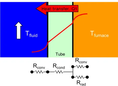
fluidFigure 2. Heat transfer through a clean tube. Heat is transferred by conduction through the tube. There is convection on both sides of the tube, and radiation on the outside.
The resistance to the flow is composed of four parts, in series and in parallel, as is shown in the figure. On the inside there is a boundary layer with a convective resistance. Then there is the tube itself, resisting the conductive flow of heat from the outside to the inside. On the outside, heat is transferred through radiation and convection (another boundary layer). So we have a convective resistance and a radiative resistance in parallel with each other and in series with the other two.
AN OM ALI ES
There are several kinds of anomalies we look for in a furnace, but in this paper I will concentrate on two issues only, and those are scale and coke.
Scale is a layer of hard crust that forms on the outside of the tube. It contains material from the tube itself, i.e. corrosion substances, and from the outside – deposits of “dirt”; carbon, sulphur, dust, etc. All those taken together form the scale. When the scale gets thick it is very common that it falls off, piece by piece, creating bare spots where the metal is nearly exposed. A thin layer of corrosion is likely to always remain, or will nearly instantly form on the surface.
Coke is formed on the inside of the tube from the process fluid itself, usually when it gets too hot. It sticks on the inside surface of the tube. With enough coke, the product flow that cools the tube will also be reduced, and the tube will heat up locally and that can cause accidents.
Coke makes the tube metal run hotter than normal, by insulating from the cooling effect of the fluid inside. Scale makes the tube metal run cooler than it would otherwise do, by insulating it from the hot furnace on the outside. Both will reduce the heat flow into the tube, and the thermal balance of the furnace will be less favorable. Fuel and money will be wasted because the burners have to be turned up to achieve the desired output temperature of the process fluid. When the burners cannot be turned up any more, for safety or capacity reasons, the flow rate of the process fluid needs to be reduced instead, which lowers the production and even more money is lost.
Here is how scale will change the picture:
R
condR
convR
convR
rad Heat t ransfer, Q2Scale layer
R
scale TubeFigure 3. Heat transfer through a tube with scale. Another resistance is added on the outside of the tube.
The thermal resistance that is added by just a thin layer of scale can easily amount to the same resistance as the rest of the tube, because the material of the scale has a much higher thermal resistance.
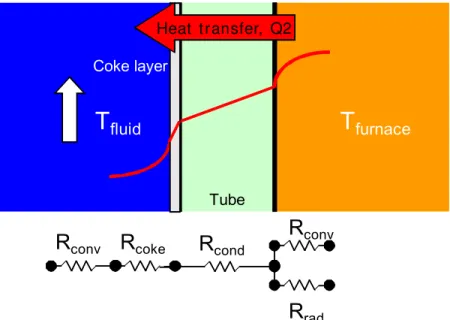
Here is how coke works, in principle. Of course, coke also has a vastly higher thermal resistance than the tube itself.
Heat t ransfer, Q2
Coke layer
Tube
T
fluidT
furnaceR
condR
convR
radR
cokeR
convFigure 4. Heat transfer through a tube with coke. Another resistance is added on the inside of the tube.
Figure 5a. Jagged and sharp edged pattern of scaled tubes.
Figure 5b. Smooth pattern of coked tubes.
T EM PERAT U RES T O CON SI DER
What is the temperature of a furnace? The answer is of course that there are millions of different temperatures inside. But let us define a set of temperatures that we can use for the further discussion.
1. “Tube skin thermometer” reading. What we read from the tube skin thermometers, which is essentially the temperature of the sensor itself.
2. Tube surface temperature. What we read with the IR camera on the surface, whatever the surface may be.
3. Metal surface temperature. The actual temperature of the tube metal surface. This temperature may not exceed the design limit of the tube material. It can only be measured with the camera on a clean tube.
M I SU N DERST AN DI N GS ABOU T T U BE SK I N T H ERM OM ET ERS
Here is another little sketch. Where exactly can we find those three temperatures?
Se n sor
Pr ot e ct iv e cov e r
4 0 0 °C
Te m p???
4 0 0 °C
4 0 0 °C
8 0 0 °C
6 0 0 °C
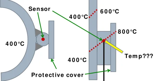
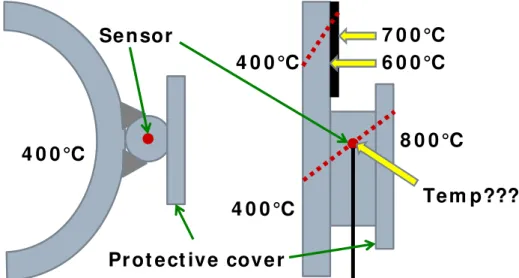
Figure 6. Sketch of the thermocouple arrangement. The temperature is taken
somewhere inside a very complicated heat transfer system. On the left is a section cut straight through the tube, and on the left it is cut along the length of the tube.
Let us first assume the following, with no scale present on the tube: - The process fluid is 400°C
- The tube surface temperature is equal to the metal surface temperature and 600°C - The protective cover of the tube skin thermometer is 800°C
“Protective cover”? Yes, they usually have protective covers on those thermometers. Why so? Look at the drawing below.
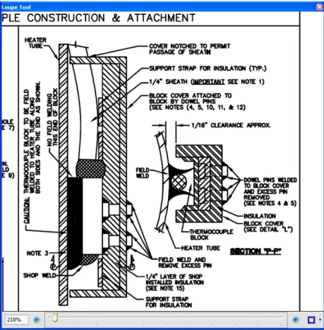
Figure 7. Design drawing of a typical tube skin thermocouple. Many designs exist.
It is a schematic of the tube skin thermometer. It is fitted onto the outside of the tube, usually welded. I think everybody will understand that if the protective cover was not there, the thermometer would be very exposed to the flames and measure much too high temperature compared to the surface of the tube, since it would not be so well cooled by the process fluid. Notice the text at the bottom where it says 1/4” LAYER OF SHOP INSTALLED INSULATION.
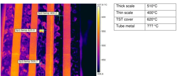
Thick scale 510°C Thin scale 400°C TST cover 620°C Tube metal ??? °C
Figure 8. Surface temperatures measured with the camera. The temperature that is closest to the tube metal temperature would be 400°C, where the insulating scale layer is thinnest. (TST reading is unknown, unfortunately.)
The sensor inside the protective cover will measure the temperature of itself, nothing else, just like any contact thermometer does. Now, consider the thermal gradients through this complex system. We have 200K between the inside and outside of the tube. If the tube is 10mm, that means a whopping 20K per millimeter! From the inside of the tube to the outside of the protective cover we have a gradient of 400K. And somewhere inside is the sensor. Exactly where do you think it will measure? And what will be the temperature in that position? IF, and only IF, the manufacturer of the tube skin thermometer does a great job of matching the insulation of the protection exactly, in such a way that the protection precisely counteracts BOTH the extra thermal resistance between the thermometer and the tube wall, AND the higher heat flow from the flames, will it measure actual tube metal temperature.
I have seen examples of near perfect match between camera measurement and tube skin thermometers. The furnace was only about three months old from first commissioning and the tubes were nice and clean. That is a rare condition.
What do you think will happen when the protective cover gets some scale on it? I personally think there is a big chance it will go out of tune…
The insulating effect would increase and the reading will probably go down, because the cooling effect from the process fluid would be greater relative to the heating from the flames. The tube skin thermometer will no longer be thermally balanced.
M I SU N DERST AN DI N GS ABOU T EM I SSI V I T Y
Having said that, it does not really matter very much to us thermographers either, because the next thing that will happen is that the tube will get some scale on it, and it will look like this.
- The process fluid is 400°C
- The tube surface temperature is 700°C - The metal surface temperature is 600°C
- The protective cover of the tube skin thermometer is 800°C
Se n sor
Pr ot e ct iv e cov e r
4 0 0 °C
Te m p???
4 0 0 °C
4 0 0 °C
7 0 0 °C
8 0 0 °C
6 0 0 °C
Figure 9. Scale on the tube will change the surface temperature that the camera reads. That temperature CAN NOT be used to estimate emissivity!
Let us assume, for arguments sake, that the tube skin thermometer does in fact measure the same as true metal surface temperature in both these cases, and you are using it to make an emissivity test of the tube surface. In the first case, with the un-scaled tube, you would in fact get the true emissivity. (But you are probably just lucky, don’t forget that! So don’t make it a habit!)
In the second case, as shown above, the actual temperature of the surface will have risen by 100°C.
Comparing the tube skin reading and the camera, you find that the camera is reading “too high”. You place a lot of trust in your tube skin thermometers so you will adjust the temperature reading of the camera with the emissivity setting so that it “reads correct”, according to the tube skin thermometers.
As I mentioned in the beginning, things go backwards sometimes in a furnace, when you change the emissivity setting. That is because we a looking at a cooler target in a warmer surrounding. (If you don’t believe me, play with your camera a bit and you will see.)
If you have done things correctly with the RAT, you will have set a RAT that is higher than your tube temperature (see my paper at InfraMation 2002 for an explanation). In such a case, a lower setting of the emissivity will give you a lower temperature reading on the cooler tube. So that is what you will do to get the “correct” emissivity in this case. And you say to yourself: “Gee, the tube with a lot of corrosion and dirt on it has gotten a lower emissivity than when it was nice and clean. Imagine that!” Well, well. Seriously, folks!
Myth killed: Contrary to popular belief, you cannot use tube skin thermometer values to measure emissivity.
H OW M U CH DOES AN AN OM ALY CH AN GE T H E H EAT FLOW RAT E T H ROU GH T H E T U BE WALL?
When we get scale and/or coke, both conditions will insulate the tube and reduce the heat flow rate to the fluid inside. That can be counteracted by turning up the burners and increasing the temperature difference (i.e. turn up the burners), so that the output temperature is maintained.
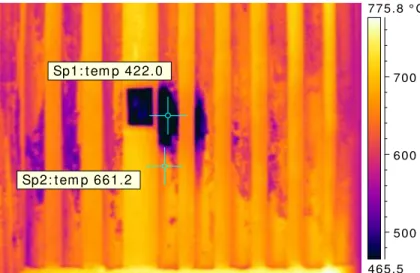
Here is a thermogram that shows this very well, with heavily scaled tubes.
Sp1: t em p 422.0
Sp2: t em p 661.2
465.5 775.8 ° C
500 600 700
Figure 10. Furnace tube with a clean spot. Where the tube is clean, it is thermally efficient and we are reading very close to true metal temperature with the camera, until scale is formed again.
The dark area next to the porthole has been cleaned with steam, so that no scale is present anymore. We are now looking at a clean tube surface at that point. The immediate reaction from many thermographers will be that the emissivity has now gone down, so we have a reflection. No, think again! The tube is COLD compared to everything else in the furnace. If it would reflect a lot, it would look HOTTER. I am still using the same emissivity value, because although clean from scale, the thin oxide layer on the surface will never quite go away, so we are still looking at oxide, not metal.
“T H E COLD SPOT I S T H E H OT SPOT ”
If you are asked to find out whether it is safe to increase the firing of the burners with regard to tube temperature and furnace safety, you need to think clearly about what they are asking about and where you should look to find the answer. If you are asked that question, it may be because coke and/or scale has reduced the efficiency of the furnace, and the operations people want more heat into the process fluid. You should first find out if there is any coke and deal with that issue. This is a qualitative analysis task that is partly outside the scope of this paper. But the interesting temperature will be the hot temperature on the tube surface where there is coke behind. That is the dangerous one! I suggest that whatever you measure on a coked tube must be considered the critical one, no matter if there is also scale on the tube that is insulating.
In reality, so far many thermographers seem to have compensated one mistake with another, using an emissivity setting that is based on thermocouple reading and consequently much too low. The result is closer to what everybody wishes it to be, but not necessarily correct.
FU RN ACE T U BE EM I SSI V I T Y
So what is the emissivity of a furnace tube then? If the tube skin thermometers cannot help us measure emissivity, how shall we measure it? There really is no practical way of measuring emissivity on a furnace tube in operation. If someone has a suggestion, please bring it forward! We could take samples of course and do a test outside the furnace. That is on my wish list but not yet a reality. Also, I somehow doubt the
usefulness of such a measurement…
There are six factors that influence emissivity:
• material
• surface condition
• angle
• geometry
• wavelength
• temperature.
Material: The material we actually look at will be metal oxide mixed with “dirt”, the slag products that are formed on the surface. We will never look at actual metal, not even on most brand new tubes, and if so, the tubes will most likely corrode very quickly on the surface anyway. Conclusion: High emissivity.
Surface condition: The surface will usually be rough. Conclusion: High emissivity.
Angle: The angle will be varying, but in the middle we will look straight on the tube. Conclusion: Emissivity will usually not be reduced by angle effects on a furnace tube, other than at the edges.
Geometry: The geometry factor will not be relevant, because there are usually no holes, angles, or cavities to consider. Conclusion: Not applicable.
Wavelength: The wavelength will be a narrow band of 3.9 micrometer. Emissivity can be slightly lower with shorter wavelengths on some materials, sometimes because there may be some transmissivity and metal will be seen through. But corrosion products and scale are not likely to be among materials that are transparent. The furnace camera will have a narrow band filter, so emissivity will not be changing for spectral reasons either. Conclusion: No big reason to suspect low emissivity.
Temperature: The temperature will be high. High temperature on metals usually means high emissivity. And again, there is no reason for emissivity to change because of spectral issues. Conclusion: Emissivity is probably high.
So, given the conditions of the furnace tube I ask, what reason do we have to believe that the emissivity will be low? I really cannot find any at all. I think the most important factor is the material – metal oxide and dirt. In any situation I have come across so far as a thermographer, metal oxide and dirt have always had high emissivity, up around 0.95.
It will be very hard to convince me that the emissivity will go down below 0.90 on a furnace tube. There are simply no reasons why it would, as far as I can see. Above 0.95 is unusual to find anywhere. So somewhere between 0.90 and 0.95 is my estimation. So I use 0.93 as a default value in furnaces, simply because we must put a precise value. But if you vary it up and down between 0.90 and 0.95 you will find that it makes a rather small difference at such a high emissivity.
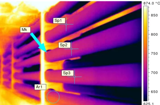
Sp3 Sp2
Ar1
Sp1
Mk
625.1 874.0 ° C
650 700 750 800 850
Figure 11. Stainless tubes in the convection section. The combustion gases are flowing from left to right and slightly from below in the image.
We really just have to look at the image to see that the emissivity of those tubes cannot be low. It must be high. Yes, the tubes are stainless steel, but no, we are not looking at a stainless steel surface at all, because with a true stainless steel surface we should see some reflection from the hot bracket next to the tube, at the arrow. But there is no reflection! Hence, it must be low reflectivity and high emissivity. Wishful thinking however, dictated that the emissivity must be lower, so that the measured value would be lower, so that the tube would not be too hot relative to its specification. Now, the tube may not be too hot anyway, just have some insulating scale on it, as was explained above. The table below shows the results of different emissivity setting.
Emissivity 0.93
Reflected Apparent Temperature 815.0 °C Atmospheric Temperature 990.0 °C
Object Distance 1.0 m
Ar1 Max. Temperature 789.0 °C
Sp1 Temperature 724.4 °C
Sp2 Temperature 723.3 °C
Sp3 Temperature 724.5 °C
Emissivity 0.70
Reflected Apparent Temperature 815.0 °C Atmospheric Temperature 990.0 °C
Object Distance 1.0 m
Ar1 Max. Temperature 780.2 °C
Sp1 Temperature *690.8 °C
Sp2 Temperature *689.2 °C
Sp3 Temperature *691.0 °C
Figure 12. Using correct emissivity will show surface temperature above tube specification, which is 700°C.
CON CLU SI ON S
Furnace tube measurements have been done for a long time, but so far with false assumptions, in my opinion.
I have seen so many examples of thermographers who glean at thermocouples and try to set the camera so that it measures “reasonably correct” values. We have to start trusting ourselves and our instruments and not let ourselves be persuaded that the tube skin thermometers are always “right”.
For me, the key to unlocking the mystery has been the understanding that the scale on the tube has a much higher thermal resistance than most people seem to realize, and that emissivity is no big deal – if all known facts tell us that it should be high, why would it be anything else? Once those misunderstandings are out of the way, the pieces of the puzzle start to fall into place quite nicely.
With this understanding, we now need new methodologies and procedures to use the IR camera for furnaces, and I am developing just that. What is required is a systematic approach that uses baselining and trending to see how the furnace changes with time, among other things.
TO BE CONTINUED…
ABOU T T H E AU T H OR
Mikael Cronholm is a Level III thermographer and has been working in the thermography industry for nearly 20 years. He started his career as a Product Manager at Agema Infrared Systems in Sweden, which is now a part of FLIR. From 1992 and onwards, Mikael has been self employed with consulting and training. After five years of teaching in and around Sweden he joined ITC as a Licensed Instructor in 1999 and has been teaching thermography all over the world, in a total of 35 different countries so far. After moving to Thailand a few years ago, he is now building a business there as a distributor of FLIR Systems and other IR related brands. However, travelling and training remains on the agenda with around 25 courses per year.
Mikael developed the Level 1 training course for ITC in 2002 and the course has been very popular around the world since then – it is now translated into over 17 languages! Most recently, Mikael has developed an Advanced Management and Applications course for Industrial Thermography, and two training courses on furnace tube thermography, one Basic for beginners and one Advanced that requires Level 1 first.