NOT FOR DISTRIBUTION
For Intro to Physical C
at ITP
/NYU 2012
NOT FOR DISTRIBUTION
For Intro to Physical C
omputing
at ITP
NOT FOR DISTRIBUTION
For Intro to Physical C
omputing
at ITP
/NYU 2012
NOT FOR DISTRIBUTION
For Intro to Physical C
omputing
at ITP
BOOK
NOT FOR DISTRIBUTION
For Intro to Physical C
at ITP
/NYU 2012
NOT FOR DISTRIBUTION
For Intro to Physical C
omputing
at ITP
THE ARDUINO PROJECTS BOOK
EDITORS
Projects and text by Scot Fitzgerald and Michael Shiloh Additional text review by Tom Igoe
DESIGN AND ART DIRECTION TODO
Giorgio Olivero, Mario Ciardulli, Vanessa Poli, Michelle Nebiolo todo.to.it
DIGITAL FABRICATION AND PROJECT MANAGEMENT Oficine Arduino Torino
Katia De Coi, Enrico Bassi ADVISORS AND SUPPORTERS
Massimo Banzi, Gianluca Martino, Smart Projects PROJECT TESTERS AND PROOFREADERS
Michael Shiloh, Michelle Nebiolo, Katia De Coi, Alessandro Buat, Federico Vanzati, David Mellis
THANKS
Big thanks to the entire Arduino user community for their contin-ued contributions, support, and feedback.
Special thanks to the Fritzing team: some of the electronic com-ponents illustrations used in the book are taken or modiied from the open-source Fritzing project (www.fritzing.org).
Heartfelt thanks to Paul Badger for the CapacitiveSensor library used in Project 13.
The text of the Arduino Projects Book is licensed under a Creative Commons Atribution-NonCommercial-ShareAlike 3.0 License 2012 by Arduino LLC. This means that you can copy, reuse, adapt and build upon the text of this book non-commercially while atributing the original work (but not in any way that suggests that we endorse you or your use of the work) and only if the results are transmited under the same Creative Commons license.
Full license terms: creativecommons.org/licenses/by-nc-sa/3.0/ © 2012 Arduino LLC. The Arduino name and logo are trademarks of Arduino, registered in the US and in the rest of the world. Other product and company names mentioned herein are trademarks of their respective companies.
The information in this book is distributed on an “As Is” basis without any further warranties. While every precaution has been taken in the design of this book, neither the authors nor Arduino LLC shall have any liability to any person or entity with respect to any loss or damage caused or declared to be caused directly or indirectly by the instructions contained in this book or by the sotware and hardware described in it.
This book cannot be sold separately from The Arduino Starter Kit. Designed, printed and bound in Torino, Italy
September 2012
NOT FOR DISTRIBUTION
For Intro to Physical C
omputing
at ITP
/NYU 2012
NOT FOR DISTRIBUTION
For Intro to Physical C
omputing
at ITP
00 INTRODUCTION
01 Get to Know Your Tools
02 Spaceship Interface
03 Love-o-Meter
04 Color Mixing Lamp
05 Mood Cue
06 Light Theremin
07 Keyboard Instrument
08 Digital Hourglass
09 Motorized Pinwheel
10 Zoetrope
11 Crystal Ball
12 Knock Lock
13 Touchy-feely Lamp
14 Tweak the Arduino Logo
15 Hacking Butons
A/Z GLOSSARY
4
20
32
42
52
62
70
78
86
94
102
114
124
136
144
156
162
NOT FOR DISTRIBUTION
For Intro to Physical C
at ITP
/NYU 2012
NOT FOR DISTRIBUTION
For Intro to Physical C
omputing
at ITP
00
BECOME EXTRAORDINARY
Everyone, every day, uses technology. Most of us leave the programming to engineers because we think coding and electronics are complicated and diicult; actually, they can be fun and exciting activities. Thanks to Arduino, designers, artists, hobbyists and students of all ages are learning to create things that light up, move, and respond to people, animals, plants, and the rest of the world.
Over the years Arduino has been used as the “brain” in thousands of projects, one more creative than the last. A worldwide community of makers has gathered around this open-source platform, moving from personal computing to personal fabrication, and contributing to a new world of participation, cooperation and sharing.
Arduino is open and simple. It’s founded on lessons we’ve learned teaching our own classes: if you start with the assumption that learning to make digital technologies is simple and accessible, you can make it so. Suddenly electronics and code become creative tools that anyone can use – like brushes and paint. This book walks you through the basics in a hands-on way, with creative projects you build by learning. Once you’ve mastered the basics, you’ll have a palete of sotware and circuits that you can use to create something beautiful, and make someone smile with what you invent.
NOT FOR DISTRIBUTION
For Intro to Physical C
omputing
at ITP
/NYU 2012
NOT FOR DISTRIBUTION
For Intro to Physical C
omputing
at ITP
ARDUINO MAKES IT AS EASY AS POSSIBLE TO PROGRAM TINY COMPUTERS CALLED MICROCONTROLLERS, WHICH ARE WHAT MAKE OBJECTS INTERACTIVE
You are surrounded by dozens of them every day: they are embedded in timers, thermostats, toys, remote controls, microwave ovens, even some toothbrushes. They just do one speciic task, and if you hardly notice them – which is oten the case – it’s because they are doing it well. They have been programmed to sense and control activity using sensors and actuators.
Sensors listen to the physical world. They convert energy that you give of when you press butons, or wave your arms, or shout, into electrical signals. Butons and knobs are sensors that you touch with your ingers, but there are many other kinds of sensors.
Actuators take action in the physical world. They convert electrical energy back into physical energy, like light and heat and movement.
Microcontrollers listen to sensors and talk to actuators. They decide what to do based on a program that you write.
Microcontrollers and the electronics you atach to them are just the skeleton of your projects, though. You’ll need to bring skills you probably already have to put some lesh on the bones.
For example, in one of the projects we suggest, you’ll make an arrow and atach it to a motor, and put them both in a box with a knob, so you can make a meter to tell people whether you’re busy or not. In another, you’ll put some lights and a tilt switch on a cardboard frame to make an hourglass.
Arduino can make your projects responsive, but only you can make them beautiful. We’ll provide some suggestions along the way as to how you might do that.
Arduino was designed to help you get things done. To make that happen, we kept the background material on programming and electronics to a minimum. If you decide you want to know more about these aspects, there are lots of good guides available. We’ll provide a couple of references, and you can ind more online at: arduino.cc/starterkit
NOT FOR DISTRIBUTION
For Intro to Physical C
at ITP
/NYU 2012
NOT FOR DISTRIBUTION
For Intro to Physical C
omputing
at ITP
Arduino Uno - The microcontroller develop-ment board that will be at the heart of your projects. It’s a simple computer, but one that has no way for you to interact with it yet. You will be building the circuits and interfaces for interaction, and telling the microcontroller how to interface with other components.
+
-+
-+
-+
-Batery Snap - Used to connect a 9V batery to power leads that can be easily plugged into a breadboard or your Arduino.
Breadboard - A board on which you can build electronic circuits. It’s like a patch panel, with rows of holes that allow you to connect wires and components together. Versions that re-quire soldering are available, as well as the sol-der-less type used here.
Capacitors - These components store and re-lease electrical energy in a circuit. When the circuit’s voltage is higher than what is stored in the capacitor, it allows current to low in, giv-ing the capacitor a charge. When the circuit’s voltage is lower, the stored charge is released. Oten placed across power and ground close to a sensor or motor to help smooth luctuations in voltage.
DC motor - Converts electrical energy into me-chanical energy when electricity is applied to its leads. Coils of wire inside the motor become magnetized when current lows through them.
+
PARTS IN
YOUR KIT
6
Welcome to Arduino! Introduction
NOT FOR DISTRIBUTION
For Intro to Physical C
omputing
at ITP
/NYU 2012
NOT FOR DISTRIBUTION
For Intro to Physical C
omputing
at ITP
These magnetic ields atract and repel mag-nets, causing the shat to spin. If the direction of the electricity is reversed, the motor will spin in the opposite direction.
Diode - Ensures electricity only lows in one di-rection. Useful when you have a motor or other high current/voltage load in your circuit. Di-odes are polarized, meaning that the direction that they’re placed in a circuit maters. Placed one way, they allow current to pass through. Placed the other way, they block it. The anode side generally connects to the point of higher energy in your circuit. The cathode typically connects to the point of lower energy, or to ground. The cathode is usually marked with a band on one side of the component’s body.
Gels (red, green, blue) - These ilter out difer-ent wavelengths of light. When used in con-junction with photoresistors, they cause the sensor to only react to the amount of light in the iltered color.
H-bridge - A circuit that allows you to control
the polarity of the voltage applied to a load, usually a motor. The H-bridge in the kit is an in-tegrated circuit, but it could also be construct-ed with a number of discrete components.
Jumper wires - Use these to connect
compo-nents to each other on the breadboard, and to the Arduino.
Light Emiting Diodes (LEDs) - A type of diode that illuminates when electricity passes through it. Like all diodes, electricity only lows in one direction through these components. You’re probably familiar with these as indicators on a variety of electronic devices. The anode, which typically connects to power, is usually the long-er leg, and the cathode is the shortlong-er leg.
Liquid Crystal Display (LCD) - A type of alpha-numeric or graphic display based on liquid crys-tals. LCDs are available in a many sizes, shapes, and styles. Yours has 2 rows with 16 characters each.
- +
-
+
NOT FOR DISTRIBUTION
For Intro to Physical C
omputing
at ITP
/NYU 2012
NOT FOR DISTRIBUTION
For Intro to Physical C
omputing
at ITP
Resistors - Resist the low of electrical energy in a circuit, changing the voltage and current as a result. Resistor values are measured in ohms (represented by the Greek omega char-acter: Ω). The colored stripes on the sides of resistors indicate their value (see resistor color code table).
Optocoupler - This allows you to connect two circuits that do not share a common power supply. Internally there is a small LED that, when illuminated, causes a photoreceptor in-side to close an internal switch. When you ap-ply voltage to the + pin, the LED lights and the internal switch closes. The two outputs replace a switch in the second circuit.
Piezo - An electrical component that can be used to detect vibrations and create noises.
Photoresistor - (also called a photocell, or light-dependent resistor). A variable resistor that changes its resistance based on the amount of light that falls on its face.
Potentiometer - A variable resistor with three pins. Two of the pins are connected to the ends of a ixed resistor. The middle pin, or wiper, moves across the resistor, dividing it into two halves. When the external sides of the poten-tiometer are connected to voltage and ground, the middle leg will give the diference in voltage as you turn the knob. Oten referred to as a pot.
Pushbutons - Momentary switches that close
a circuit when pressed. They snap into bread-boards easily. These are good for detecting on/ of signals.
Male header pins - These pins it into female sockets, like those on a breadboard. They help make connecting things much easier.
8
Welcome to Arduino! Introduction
NOT FOR DISTRIBUTION
For Intro to Physical C
omputing
at ITP
/NYU 2012
NOT FOR DISTRIBUTION
For Intro to Physical C
omputing
at ITP
USB Cable - This allows you to connect your Arduino Uno to your personal computer for programming. It also provides power to the Ar-duino for most of the projects in the kit. Temperature sensor - Changes its voltage
out-put depending on the temperature of the com-ponent. The outside legs connect to power and ground. The voltage on the center pin changes as it gets warmer or cooler.
Tilt sensor - A type of switch that will open or close depending on its orientation. Typically they are hollow cylinders with a metal ball in-side that will make a connection across two leads when tilted in the proper direction.
Transistor - A three legged device that can op-erate as an electronic switch. Useful for
control-ling high current/high voltage components like motors. One pin connects to ground, another to the component being controlled, and the third connects to the Arduino. When the com-ponent receives voltage on the pin connected to an Arduino, it closes the circuit between the ground and the other component.
Servo motor - A type of geared motor that
can only rotate 180 degrees. It is controlled by sending electrical pulses from your Arduino. These pulses tell the motor what position it should move to.
NOT FOR DISTRIBUTION
For Intro to Physical C
omputing
at ITP
/NYU 2012
NOT FOR DISTRIBUTION
For Intro to Physical C
omputing
at ITP
TABLE OF SYMBOLS UNCONNECTED WIRES
LED DIODE
PUSHBUTTON
PIEZO TILT SWITCH
POL ARIZED CAPACITOR
MOSFET TRANSISTOR
CAPACITOR
MOTOR
BATTERY RESISTOR
GROUND
PHOTO RESISTOR POTENTIOMETER
In this book we will show you circuits both with realistic illustrations and with schematic diagrams.
Illustrations will give you an idea of what the breadboard might look like in one possible implementation of the project. Schematics, instead, use symbols to capture the essence of circuits: they present the components and the ways they are connected in a clear, succinct, and unambiguous form, but not their physical organization. Schematics and schematic symbols are how we communicate about circuits. As you explore the world of electronics you will discover that some books and websites only provide schematic diagrams, so learning to read circuits this way is a valuable skill.
Here are the symbols we will be using throughout the book.
CONNECTED WIRES
NOT FOR DISTRIBUTION
For Intro to Physical C
omputing
at ITP
/NYU 2012
NOT FOR DISTRIBUTION
For Intro to Physical C
omputing
at ITP
THE BOARD
USB port
Used for powering your Arduino Uno, uploading your sketches to your Arduino, and for communicating with your Arduino sketch (via Serial. println() etc.)
ATmega microcontroller
The heart of your Arduino Uno.
Power connector
This is how you power your Arduino when it's not plugged into a USB port for power. Can accept voltages between 7-12V.
Reset Button
Resets the ATmega microcontroller.
TX and RX LEDs
These LEDs indicate communi-cation between your Arduino and your computer. Expect them to flicker rapidly during sketch upload as well as during serial communication. Useful for debugging.
Pin 13 LED
The only actuator built-it to your Arduino Uno. Besides being a handy target for your first blink sketch, this LED is very useful for debugging.
Power LED
Indicates that your Arudino is receiving power. Useful for debugging.
Analog in
Use these pins with analogRead().
GND and 5V pins
Use these pins to provide +5V power and ground to your circuits.
Digital pins
Use these pins with digital-Read(), digitalWrite(), and analogWrite(). analogWrite() works only on the pins with the PWM symbol.
NOT FOR DISTRIBUTION
For Intro to Physical C
omputing
at ITP
/NYU 2012
NOT FOR DISTRIBUTION
For Intro to Physical C
omputing
at ITP
Your Starter Kit includes a pre-cut, easy-to-assemble wooden base that will make working on all your projects – whether they are from this book or not
– even easier.
To build it, take the wood sheet out of the box and follow the instructions on the right.
Be careful to use only the parts that are shown, but don’t misplace any of the other pieces: you’ll need them for some of the projects later.
Let’s start!
❶
Take the wood sheet and carefully separate the pieces.
❹
Secure your Arduino Uno to the base using 3 screws. Be careful not to overtightens.
12
Welcome to Arduino! Introduction
NOT FOR DISTRIBUTION
For Intro to Physical C
omputing
at ITP
/NYU 2012
NOT FOR DISTRIBUTION
For Intro to Physical C
omputing
at ITP
❷
Go on until you’ve separated all the parts.
❸
Place the pieces marked with an “A” into the holes in the corners, in order to create the feet of the base.
❺
Carefully peel the backing from the breadboard.
❻
Stick the breadboard on the wooden sheet, next to the Arduino UNO.
NOT FOR DISTRIBUTION
For Intro to Physical C
omputing
at ITP
/NYU 2012
NOT FOR DISTRIBUTION
For Intro to Physical C
omputing
at ITP
9V batery
Small light source like a lashlight
Conductive material like aluminum foil or copper mesh
Colored paper
Scissors
An old CD or DVD
Tape and glue
THINGS YOU
NEED TO
SUPPLY
-A box that you can make holes into
Basic tools like a screwdriver
9V batery powered component
Any batery powered electronic device with at least one switch or pushbuton that you’re will-ing to hack into will do the job.
Soldering iron and solder
(necessary only in Project 15)
14
Welcome to Arduino! Introduction
NOT FOR DISTRIBUTION
For Intro to Physical C
omputing
at ITP
/NYU 2012
NOT FOR DISTRIBUTION
For Intro to Physical C
omputing
at ITP
WELCOME TO ARDUINO! BEFORE YOU START CONTROLLING THE WORLD AROUND YOU, YOU’LL NEED TO DOWNLOAD THE IDE TO PROGRAM YOUR BOARD
The Arduino IDE allows you to write programs and upload them to your Arduino.
Download the latest version of the IDE from: arduino.cc/download
Have your Arduino board and USB cable near your computer. Don’t plug them in just yet.
Follow the appropriate procedures in the next pages for Windows, Mac OS X or Linux.
The online version of this guide is available at:
arduino.cc/guide
NOT FOR DISTRIBUTION
For Intro to Physical C
at ITP
/NYU 2012
NOT FOR DISTRIBUTION
For Intro to Physical C
omputing
at ITP
When the download of the IDE inishes, unzip the downloaded
ile. Make sure to preserve the folder structure. Double-click the folder to open it. There should be a few iles and sub-folders inside.
Connect the Arduino to your computer with the USB cable. Your Arduino will automatically draw power from either the USB con-nection to the computer or an external power supply. The green power light (labeled PWR) should turn on.
Windows should initiate its driver installation process when the board is plugged in. Your computer won’t be able to ind the driv-ers by itself, so you’ll need to tell it where they are located.
In the Device Manager, you should now see a port listing similar to “Arduino UNO (COM4)”.
Congratulations! You've installed the Arduino IDE on your computer.
—Click on the Start Menu and open the Control Panel. —Navigate to “System and Security”. Open the Device Manager. —In Windows XP, look for the listing named "Ports (COM & LPT)" and right click on the "USB device" port; in Vista and Windows 7, right click on "Unknown device" under "Other devices".
—Choose "Update Driver Sotware".
—On Windows XP and Windows 7, you will be asked whether to install automatically or "with a path". Chose the second option, "with a path". On Windows Vista proceed directly to the next step. —Select the “Browse my computer for Driver sotware” option. —Navigate to the folder you unzipped in the earlier step. Locate and select the “Drivers” folder in the main Arduino folder (not the “FTDI USB Drivers” sub-directory). Press “OK” and “Next” to proceed.
—If you are prompted with a warning dialog about not passing Windows Logo testing, click “Continue Anyway”.
—Windows now will take over the driver installation.
WINDOWS
INSTALLATION
Online version
arduino.cc/windows
❶
❷
❸
INSTRUCTION FOR:WINDOWS 7, VISTA, AND XP
16 Introduction
Seting Up
NOT FOR DISTRIBUTION
For Intro to Physical C
omputing
at ITP
/NYU 2012
NOT FOR DISTRIBUTION
For Intro to Physical C
omputing
at ITP
When the download of the IDE inished, double-click the .zip le.
This will expand the Arduino application.
Copy the Arduino application into the Applications folder, or wherever else you wish to install the sotware.
Connect the board to the computer with the USB cable. The green power LED (labeled PWR) should turn on.
You do not need to install any drivers to work with the board. Depending on the version of OS X that you are running, you might get a dialog box asking if you wish to open the “Network Preferences”. Click the “Network Preferences...” buton, and then click “Apply”.
The Uno will show up as “Not Conigured”, but it is still working. You can quit the System Preferences.
Congratulations! You have Arduino all set up and you're ready to start making projects.
MAC OS X
INSTALLATION
Online version
arduino.cc/mac
❶
❷
❸
❹
❺
INSTRUCTION FOR:OS X 10.5 AND LATER
If you’re using Linux, please visit the website for instructions: arduino.cc/linux
LINUX
INSTALLATION
NOT FOR DISTRIBUTION
For Intro to Physical C
omputing
at ITP
/NYU 2012
NOT FOR DISTRIBUTION
For Intro to Physical C
omputing
at ITP
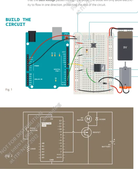
Fig. 1
COMMUNICATING
WITH THE
ARDUINO
Now that you’ve installed the Arduino IDE and made sure your computer can talk to the board, it’s time to make sure you can up-load a program.
Double-click the Arduino application to open it. If the IDE loads in the wrong language, you can change this in the application preferences. Look for “Language Support” on this page for de-tails: arduino.cc/ide
Navigate to the LED blink example sketch ('sketch' is what Ar-duino programs are called). It's located under:
FILE > EXAMPLES > 01.BASICS > BLINK
A window with some text in it should have opened. Leave the window be for now, and select your board under:
TOOLS > BOARD menu
18 Introduction
Seting Up
Choose the serial port your Arduino is connected to from the
TOOLS > SERIAL PORT menu.
—On Windows. This is likely to be the COM with the highest number. There is no harm in guessing wrong, and if it doesn’t work, try the next one. To ind out, you can disconnect your Arduino board and re-open the menu; the entry that disappears should be the Arduino board. Reconnect the board and select that serial port.
—On Mac. This should be something with /dev/ty.usbmodem in it. There are usually two of these; select either one.
To upload the Blink sketch to your Arduino, press the UPLOAD
toggle in the top let corner of the window. See Fig. 1.
❶
❷
❸
❹
❺
NOT FOR DISTRIBUTION
For Intro to Physical C
omputing
at ITP
/NYU 2012
NOT FOR DISTRIBUTION
For Intro to Physical C
omputing
at ITP
Fig. 2
ADDITIONAL
INFORMATION
You should see a bar indicating the progress of the upload near the lower let corner of the Arduino IDE, and the lights labeled TX and RX on the Arduino board will be blinking. If the upload is successful, the IDE will display the message DONE UPLOADING.
A few seconds ater the upload has completed, you should see the yellow LED with an L next to it start blinking. See Fig. 2.
If this is the case, congratulations! You’ve successfully pro-grammed the Arduino to blink its onboard LED!
Sometimes your brand new Arduino is already programmed with the Blink sketch, so you can’t tell if you are truly in control. If this is the case, change the delay time by changing the number in the parenthesis to 100, and upload the Blink sketch again. Now the LED should blink much faster.
Congratulations! You really are in control!Now it’s time to move on to Project 1. (You needn’t save any changes you have made.)
If you have problems with any of the steps outlined above, please see the troubleshooting suggestions:
arduino.cc/trouble
While you’re geting ready to build your projects, you can look at the following page for additional information about the Arduino’s programming environment:
arduino.cc/ide
You might also want to look at:
—the examples for using various sensors and actuators arduino.cc/tutorial
—the reference for the Arduino language arduino.cc/examples
❻
❼
NOT FOR DISTRIBUTION
For Intro to Physical C
omputing
at ITP
/NYU 2012
NOT FOR DISTRIBUTION
For Intro to Physical C
omputing
at ITP
SWITCH LED 220 OHM RESISTOR
INGREDIENTS
01
NOT FOR DISTRIBUTION
For Intro to Physical C
omputing
at ITP
/NYU 2012
NOT FOR DISTRIBUTION
For Intro to Physical C
omputing
at ITP
YOU’LL MAKE A SIMPLE CIRCUIT WITH SOME SWITCHES, AN LED, AND A RESISTOR
Electricity is a type of energy, much like heat, gravity, or light. Electrical energy lows through conductors, like wire. You can convert electrical energy into other forms of energy to do something interesting, like turn on a light or make some noise out of a speaker.
The components you might use to do this, like speakers or light bulbs, are electri-cal transducers. Transducers change other types of energy into electrielectri-cal energy and vice versa. Things that convert other forms of energy into electrical energy are oten called sensors, and things that convert electrical energy into other forms of energy are sometimes called actuators. You will be building circuits to move electricity through diferent components. Circuits are closed loops of wire with a power source (like a batery) and something to do something useful with the energy, called a load.
In a circuit, electricity lows from a point of higher potential energy (usually re-ferred to as power or +) to a point of lower potential energy. Ground (oten repre-sented with a - or GND) is generally the point of least potential energy in a circuit. In the circuits you are building, electricity only lows in one direction. This type of circuit is called direct current, or DC. In alternating current (AC) circuits electricity changes its direction 50 or 60 times a second (depending on where you live). This is the type of electricity that comes from a wall socket.
There are a few terms you should be familiar with when working with electri-cal circuits. Current (measured in amperes, or amps; with the A symbol) is the amount of electrical charge lowing past a speciic point in your circuit. Voltage (measured in volts; with the V symbol) is the diference in energy between one point in a circuit and another. And inally, resistance (measured in ohms; with the
Ω symbol) is how much a component resists the low of electrical energy.
GET TO KNOW
YOUR TOOLS
Time:
30 MINUTES
Level:Discover: basic electrical theory, how a breadboard works, components in series and parallel
NOT FOR DISTRIBUTION
For Intro to Physical C
omputing
at ITP
/NYU 2012
NOT FOR DISTRIBUTION
For Intro to Physical C
omputing
at ITP
One way to imagine this is to think about a rockslide going down a clif, as shown in Fig. 1. The higher the clif, the more energy the rocks will have when they hit the botom. The height of the clif is like the voltage in a circuit: the higher the voltage at the energy source, the more energy you have to use. The more rocks you
have, the more energy is being carried down the clif. The num-ber of rocks is like the current in an electrical circuit. The rocks go through bushes on the side of the clif, losing some energy in the process; the energy is used up to crush the bushes. The bushes are like resistors in a circuit, ofering resistance to the electrical low and converting it into other forms of energy.
There needs to be a complete path from the energy source (power) to the point of least energy (ground) to make a circuit. If there’s no path for the energy to travel, the circuit won’t work.
All the electrical energy gets used up in a circuit by the com-ponents in it. Each component converts some of the energy into another form of energy. In any circuit, all of the voltage is con-verted to another form of energy (light, heat, sound, etc.).
The low of current at a speciic point in a circuit will always be the same coming in and going out.
Electrical current will seek the path of least resistance to ground. Given two possible paths, more of the electrical current will go down the path with less resistance. If you have a connec-tion that connects power and ground together with no resist-ance, you will cause a short circuit, and the current will try to follow that path. In a short circuit, the power source and wires convert the electrical energy into light and heat, usually as sparks or an explosion. If you’ve ever shorted a batery and seen sparks, you know how dangerous a short circuit can be.
Voltage (V)
Resistance (R) Current (I)
22
Get to Know Your Tools Project 01
A COUPLE OF
THINGS ABOUT
CIRCUITS
Rockslide as a metaphor for electrical current flow.Fig. 1
The current at (1) = current at (2) + current at (3) = current at (4).
Fig. 2 5 V 1 +5V GND 2 1 4 3
NOT FOR DISTRIBUTION
For Intro to Physical C
omputing
at ITP
/NYU 2012
NOT FOR DISTRIBUTION
For Intro to Physical C
omputing
at ITP
The breadboard is the primary place you will be building circuits. The one that comes in your kit is solderless, so named because you don’t have to solder anything together, sort of like LEGO in electronic form. The horizontal and vertical rows of the bread-board, as shown in Fig. 3, carry electrictricity through thin metal
connectors under the plastic with holes.
+ +
-The 5 holes in each horizontal row are connected electrically through metal strips inside the breadboard.
The middle row breaks the connection between the two sides of the board.
The vertical strips that run the length of the breadboard are electrically connected. The strips are usually used for power and ground connections.
Conductive metal strips.
POWER BUS POWER BUS
PROTOTYPING AREA
WHAT’S A
BREADBOARD?
The top of a breadboard and the connections underneath.
Fig. 3
The conductive plates inside a breadboard.
Fig. 4
NOT FOR DISTRIBUTION
For Intro to Physical C
omputing
at ITP
/NYU 2012
NOT FOR DISTRIBUTION
For Intro to Physical C
omputing
at ITP
24
Get to Know Your Tools Project 01
Throughout these projects, you’ll see two views of circuits: one in breadboard view (like in Fig. 5), that looks like the stuf in your kit. The other is a schematic view (like in Fig. 6), which is a more abstract way of showing the relationships between components in a circuit. Schematics don’t always show where components are placed
rela-tive to each other, but they show how they are connected.
+- +
-+ -+
-CIRCUIT
DRAWINGS
Circuit illustration.
Fig. 5
Schematic view
Fig. 6
NOT FOR DISTRIBUTION
For Intro to Physical C
omputing
at ITP
/NYU 2012
NOT FOR DISTRIBUTION
For Intro to Physical C
omputing
at ITP
An LED, or light-emiting diode, is a component that converts electrical energy into light energy. LEDs are polarized components, which means they only allow electricity to low through them in one direction. The longer leg on the LED is called an anode, it will connect to power. The shorter leg is a cathode and will con-nect to ground. When voltage is applied to the anode of the LED, and the cathode is connected to ground, the LED emits light.
A resistor is a component that resists the low of electrical energy (see the com-ponents list for an explanation on the colored stripes on the side). It converts some of the electrical energy into heat. If you put a resistor in series with a com-ponent like an LED, the resistor will use up some of the electrical energy and the LED will receive less energy as a result. This allows you to supply components with the amount of energy they need. You use a resistor in series with the LED to keep it from receiving too much voltage. Without the resistor, the LED would be brighter for a few moments, but quickly burn out.
A switch interrupts the low of electricity, breaking the circuit when open. When a switch is closed, it will complete a circuit. There are many types of switches. The ones in your kit are called momentary switches, or pushbutons, because they are only closed when pressure is applied.
YOUR FIRST
COMPONENTS
The switch
Fig. 7 -CATHODE
These two pins of a switch are connected to each other
These two are not. They form the switch
SWITCH SCHEMATIC VIEW
A - Toggle switch symbol SWITCH CONNECTIONS
B - Pushbutton symbol +ANODE
NOT FOR DISTRIBUTION
For Intro to Physical C
omputing
at ITP
/NYU 2012
NOT FOR DISTRIBUTION
For Intro to Physical C
omputing
at ITP
26
Get to Know Your Tools Project 01
Fig. 8
BUILD THE
CIRCUIT
+- +
-+
-+
-Fig. 9
Your first interactive circuit, using a
switch, a resistor and an LED.
Arduino is just the power source for
this circuit; in later projects, you'll
connect its input and output pins to
control more complex circuits.
NOT FOR DISTRIBUTION
For Intro to Physical C
omputing
at ITP
/NYU 2012
NOT FOR DISTRIBUTION
For Intro to Physical C
omputing
at ITP
You’re going to use the Arduino in this project, but only as a source of power. When plugged into a USB port or a 9-volt bat-tery, the Arduino will provide 5 volts between its 5V pin and its
ground pin that you can use. 5V = 5 volts, you’ll see it writen this way a lot.
If your Arduino is connected to a batery or computer via USB, unplug it before building the circuit!
Connect a red wire to the 5V pin on the Arduino, and put the other end in one of the long bus lines in your breadboard. Con-nect ground on the Arduino to the adjacent bus line with a black wire. It’s helpful to keep your wire color consistent (red for pow-er, black for ground) throughout your circuit.
Now that you have power on your board, place your switch across the center of the board. The switch will sit across the center in one direction. The bend in the legs of the switch point to the center of the board.
Use a 220-ohm resistor to connect power to one side of the switch. The illustrations in this book use 4 bands. Your kit may have a mix of 4 and 5 band resistors. Use the illustration on the side to check for the right one for this project. Look at page 41 for a detailed explanation of the color codes for resistors.
On the other side of the switch, connect the anode (long leg) of the LED. With a wire connect the cathode (short leg) of the LED to ground. When you’re ready, plug the USB cable into the Arduino.
Once everything is set to go, press the buton. You should see the LED light up. Congratulations, you just made a circuit! Once you’ve tired of pressing the buton to turn the light on, it’s time to shake things up by adding a second buton.
USE IT
You’ll be placing components on the breadboard in series and in parallel. Components in series come one ater another. Components in parallel run side by side.
❶
❷
❸
❹
NOT FOR DISTRIBUTION
For Intro to Physical C
omputing
at ITP
/NYU 2012
NOT FOR DISTRIBUTION
For Intro to Physical C
omputing
at ITP
28
Get to Know Your Tools Project 01
Once you’ve removed your power source add a switch next to the one already on your breadboard. Wire them together in
series as shown in Fig. 10. Connect the anode (long leg) up the LED to the second switch. Connect the LED cathode to ground. Power up the Arduino again: now to turn on the LED, you need to press both switches. Since these are in series, they both need to be closed for the circuit to be completed.
Series circuit
COMPONENTS IN SERIES COME ONE AFTER ANOTHER
+- +
-+ -+
-ALWAYS REMOVE POWER BEFORE CHANGING ANYTHING IN YOUR CIRCUIT
The two switches are in series. This means that the same electrical current flows through both of them, so that they both have to be pressed for the LED to light up.
Fig. 10
Fig. 11
These two elements are in series
NOT FOR DISTRIBUTION
For Intro to Physical C
omputing
at ITP
/NYU 2012
NOT FOR DISTRIBUTION
For Intro to Physical C
omputing
at ITP
Now that you’ve mastered the art of things in series, it’s time to wire up switches in parallel. Keep the switches and LED
where they are, but remove the connection between the two switches. Wire both switches to the resistor. Atach the other end of both switches to the LED, as shown in Fig. 12. Now when you press either buton, the circuit is completed and the light turns on.
+- +
-+ -+
-Parallel circuit
COMPONENTS IN PARALLEL RUN SIDE BY SIDE
These two switches are in parallel. This means that the electrical current is split between them. If either switch is pressed, the LED will light up.
Fig. 12
Fig. 13
These two elements are in parallel
NOT FOR DISTRIBUTION
For Intro to Physical C
omputing
at ITP
/NYU 2012
NOT FOR DISTRIBUTION
For Intro to Physical C
omputing
at ITP
V
I
R
You can use this circle to remember the relationships between voltage, current, and resistance. Put your finger over any of the three, and you see how it relates to the other two.
Current, voltage, and resistance are all related. When you change one of these in a circuit, it afects the others. The rela-tionship between them is known as Ohm's Law, named for Georg Simon Ohm, who discovered it.
VOLTAGE (V) = CURRENT (I)
*
RESISTANCE (R)When measuring amperage in the circuits you’ll be building, values will be in the milliamp range. That’s thousandths of one amp.
V
I R
V
I R
I = V / R R = V / I
V
I R
V = I
*
RIn the circuit shown in Fig. 5, you’re supplying 5 volts. The resistor ofers 220 ohms resistance. To ind the amperage used by the LED, replace the values in the equa-tion. You should have 5=I*220. Dividing both sides of the equation by 220, you’ll ind that I = .023. That’s 23 thousandths of an amp, or 23 milliamps (23 mA) used by the LED. That value is just about the maximum you can safely use with these LEDs, which is why you used a 220-ohm resistor.
You can expand this project in a number of ways, either by creating your own switch (two pieces of foil with wire work well), or creating a combination of switches and LEDs in parallel and series. What happens when you put three or four LEDs in series? What happens when they are in parallel? Why does it behave the way it does?
A multimeter is a tool that can verify the amount of resistance, current, and volt-age in your circuit. While it’s not necessary to use one for these projects, it can be a useful part of any engineer’s toolbox. There’s a good description of how to use one online atarduino.cc/multimeter
30
Get to Know Your Tools Project 01
UNDERSTANDING
OHM’S LAW
NOT FOR DISTRIBUTION
For Intro to Physical C
omputing
at ITP
/NYU 2012
NOT FOR DISTRIBUTION
For Intro to Physical C
omputing
at ITP
Fig. 14 - A multimeter
presses the buton, the lights turn on. These fundamentals
of working with electronics will be referenced and expanded
upon in the upcoming projects.
NOT FOR DISTRIBUTION
For Intro to Physical C
at ITP
/NYU 2012
NOT FOR DISTRIBUTION
For Intro to Physical C
omputing
at ITP
10 KILOHM RESISTOR SWITCH LED 220 OHM RESISTOR
INGREDIENTS
02
NOT FOR DISTRIBUTION
For Intro to Physical C
omputing
at ITP
/NYU 2012
NOT FOR DISTRIBUTION
For Intro to Physical C
omputing
at ITP
Time:
45 MINUTES
Level:YOUR ARDUINO IS GOING TO STAR IN A SCIENCE FICTION MOVIE
Now that you’ve got the basics of electricity under control, it’s time to move onto controlling things with your Arduino. In this project, you’ll be building something that could have been a spaceship interface in a 1970s science iction movie. You’ll make a cool control panel with a switch and lights that turn on when you press the switch. You can decide whether the lights mean “Engage Hyperdrive” or “Fire the lasers!”. A green LED will be on, until you press a buton. When the Arduino gets a signal from the buton, the green light will turn of and 2 other lights will start blinking.
The Arduino’s digital pins can read only two states: when there is voltage on an input pin, and when there’s not. This kind of input is normally called digital (or sometimes binary, for two-states). These states are commonly referred to as HIGH and LOW. HIGH is the same as saying “there’s voltage here!” and LOW means “there’s no voltage on this pin!”. When you turn an OUTPUT pin HIGH using a command called digitalWrite(), you’re turning it on. Measure the voltage between the pin and ground, you’ll get 5 volts. When you turn an OUTPUT pin LOW, you’re turning it of.
The Arduino’s digital pins can act as both inputs and outputs. In your code, you’ll conigure them depending on what you want their function to be. When the pins are outputs, you can turn on components like LEDs. If you conigure the pins as inputs, you can check if a switch is being pressed or not. Since pins 0 and 1 are used for communicating with the computer, it’s best to start with pin 2.
SPACESHIP
INTERFACE
Builds on project:
1
Discover: digital input and output, your first program, variables
NOT FOR DISTRIBUTION
For Intro to Physical C
omputing
at ITP
/NYU 2012
NOT FOR DISTRIBUTION
For Intro to Physical C
omputing
at ITP
+- + -+ -+
-BUILD THE
CIRCUIT
Fig. 1
Fig. 2 34
Spaceship Interface Project 02
NOT FOR DISTRIBUTION
For Intro to Physical C
omputing
at ITP
/NYU 2012
NOT FOR DISTRIBUTION
For Intro to Physical C
omputing
at ITP
Wire up your breadboard to the Arduino’s 5V and ground connections, just like the previous project. Place the two red LEDs and one green LED on the breadboard. Atach the cathode (short leg) of each LED to ground through a 220-ohm resistor.
Connect the anode (long leg) of the green LED to pin 3. Connect the red LEDs’ anodes to pins 4 and 5, respectively.
Place the switch on the breadboard just as you did in the previous project. Atach one side to power, and the other side to digital pin 2 on the Arduino. You’ll also need to add a 10k-ohm resistor from ground to the switch pin that connects to the Arduino. That pull-down resistor connects the pin to ground when the switch is open, so it reads LOW when there is no voltage coming in through the switch.
❶
❷
❶
Fold the pre-cut paper as shown.
❷
Place the folded paper over the breadboard. The three LEDs and pushbutton will help keep it in place.
You can cover the breadboard the template provided in the kit. Or you can deco-rate it to make your own launch system. The lights turning on and of mean noth-ing by themselves, but when you put them in a control panel and give them labels, they gain meaning. What do you want the green LED to mean? What do the lash-ing red LEDs mean? You decide!
NOT FOR DISTRIBUTION
For Intro to Physical C
omputing
at ITP
/NYU 2012
NOT FOR DISTRIBUTION
For Intro to Physical C
omputing
at ITP
Every Arduino program has two main functions. Functions are parts of a computer program that run speciic commands. Func-tions have unique names, and are “called” when needed. The necessary functions in an Arduino program are called setup() and loop(). These functions need to be declared, which means that you need to tell the Arduino what these functions will do. setup() and loop() are declared as you see on the right. In this program, you’re going to create a variable before you get into the main part of the program. Variables are names you give to places in the Arduino’s memory so you can keep track of what is happening. These values can change depending on your pro-gram’s instructions.
Variable names should be descriptive of whatever value they are storing. For example, a variable named switchState tells you what it stores: the state of a switch. On the other hand, a vari-able named “x” doesn’t tell you much about what it stores.
To create a variable, you need to declare what type it is. The data type int will hold a whole number (also called an integer); that’s any number without a decimal point. When you declare a variable, you usually give it an initial value as well. The declaration of the variable as every statement must end with a semicolon (;).
The setup() runs once, when the Arduino is irst powered on. This is where you conigure the digital pins to be either inputs or outputs using a function named pinMode(). The pins connected to LEDs will be OUTPUTs and the switch pin will be an INPUT.
The loop() runs continuously ater the setup() has completed. The loop() is where you’ll check for voltage on the inputs, and turn outputs on and of. To check the voltage level on a digital input, you use the function digitalRead() that checks the chosen pin for voltage. To know what pin to check, digitalRead() expects an argument.
Arguments are information that you pass to functions, telling them how they should do their job. For example, digitalRead() needs one argument: what pin to check. In your program, digitalRead() is going to check the state of
Create the loop function Configure pin functionality Let’s start coding
THE CODE
Some notes before you start
36
Spaceship Interface Project 02
NOT FOR DISTRIBUTION
For Intro to Physical C
omputing
at ITP
/NYU 2012
NOT FOR DISTRIBUTION
For Intro to Physical C
omputing
at ITP
Case sensitivity
Pay atention to the case
sensitivity in your code.
For example, pinMode is the name of
a command, but pinmode will produce an error.
1
2
3
4
5
6
7
8
9
10
void setup(){ }
void loop(){ }
int switchState = 0;
void setup(){ pinMode(3,OUTPUT); pinMode(4,OUTPUT); pinMode(5,OUTPUT); pinMode(2,INPUT); }
void loop(){
switchState = digitalRead(2);
// this is a comment
Comments
If you ever want to include natural language in your program, you can leave a comment.
Comments are notes you leave for yourself that the computer ignores. To write a
comment, add two slashes //
The computer will ignore anything on the line ater those slashes.
{ Curly brackets } Any code you write inside the curly brackets will be executed when the function is called.
NOT FOR DISTRIBUTION
For Intro to Physical C
omputing
at ITP
/NYU 2012
NOT FOR DISTRIBUTION
For Intro to Physical C
omputing
at ITP
pin 2 and store the value in the switchState variable.
If there’s voltage on the pin when digitalRead() is called, the switchState variable will get the value HIGH (or 1). If there is no voltage on the pin, switchState will get the value LOW (or 0).
Above, you used the word if to check the state of something (namely, the switch position). An if() statement in programming compares two things, and determines whether the comparison is true or false. Then it performs actions you tell it to do. When comparing two things in programming, you use two equal signs ==. If you use only one sign, you will be seting a value instead of comparing it.
digitalWrite() is the command that allows you to send 5V or 0V to an output pin. digitalWrite() takes two arguments: what pin to control, and what value to set that pin, HIGH or LOW. If you want to turn the red LEDs on and the green LED of inside your if() statement, your code would look like this .
You’ve told the Arduino what to do when the switch is open. Now deine what happens when the switch is closed. The if() statement has an optional else component that allows for something to happen if the original condition is not met. In this case, since you checked to see if the switch was LOW, write code for the HIGH condition ater the else statement.
To get the red LEDs to blink when the buton is pressed, you’ll need to turn the lights of and on in the else statement you just wrote. To do this, change the code to look like this.
Ater seting the LEDs to a certain state, you’ll want the Arduino to pause for a moment before changing them back. If you don’t wait, the lights will go back and forth so fast that it will appear as if they are just a litle dim, not on and of. This is because the Arduino goes through its loop() thousands of times each second, and the LED will be turned on and of quicker than we can perceive. The delay() function lets you stop the Arduino from executing anything for a period of time. delay() takes an argument that determines the number of milliseconds before it executes the next set of code. There are 1000 milliseconds in one second. delay(250) will pause for a quarter second.
If you run your program now,
the lights will change when you
press the switch. That’s prety
neat, but you can add a litle more
complexity to the program for a
more interesting output.
Now your program will lash the
red LEDs when the switch buton
is pressed. 38
Spaceship Interface Project 02
Build up your spaceship The if statement
NOT FOR DISTRIBUTION
For Intro to Physical C
omputing
at ITP
/NYU 2012
NOT FOR DISTRIBUTION
For Intro to Physical C
omputing
at ITP
if (switchState == LOW) {
// the buton is not pressed
digitalWrite(3, HIGH); // green LED
digitalWrite(4, LOW); // red LED
digitalWrite(5, LOW); // red LED
}
else { // the buton is pressed
digitalWrite(3, LOW); digitalWrite(4, LOW); digitalWrite(5, HIGH);
delay(250); // wait for a quarter second // toggle the LEDs
digitalWrite(4, HIGH); digitalWrite(5, LOW);
delay(250); // wait for a quarter second
}
} // go back to the beginning of the loop 11 12 13 14 15 16 17 18 19 20
It can be helpful to write out the low of your program in pseudocode: a way of describing what you want the program to do in plain language, but structured in a way that makes it easy to write a real program from it. In this case you’re
going to determine if switchState
is HIGH (meaning the buton is pressed)
or not. If the switch is pressed, you’ll turn the green LED of and the red ones on. In pseudocode, the statement could look like this:
if the switchState is LOW: turn the green LED on turn the red LEDs of
if the switchState is HIGH: turn the green LED of turn the red LEDs on
21 22 23 24 25 26 27
NOT FOR DISTRIBUTION
For Intro to Physical C
omputing
at ITP
/NYU 2012
NOT FOR DISTRIBUTION
For Intro to Physical C
omputing
at ITP
In this project, you created your irst Arduino program
to control the behavior of some LEDs based on a switch.
You’ve used variables, an if()...else statement, and functions
to read the state of an input and control outputs.
When you start creating an interface for your project, think about what people’s expectations are while using it. When they press a buton, will they want immedi-ate feedback? Should there be a delay between their action and what the Arduino does? Try and place yourself in the shoes of a diferent user while you design, and see if your expectations match up to the reality of your project.
40
Spaceship Interface Project 02
How would you get the red LEDs to be blinking when your program starts? How could you make a larger, or more complex interface for your interstellar ad-ventures with LEDs and switches?
Once your Arduino is programmed, you should see the green light turn on. When you press the switch, the red lights will start lashing, and the green light will turn of. Try changing the time of the two delay() functions; notice what happens to the lights and how the response of the system changes depending on the
speed of the lashing. When you call a delay() in your program, it stops all other functionality. No sensor readings will happen until that time period has passed. While delays are oten useful, when designing your own projects make sure they are not unnecessarily interfering with your interface.
USE IT
NOT FOR DISTRIBUTION
For Intro to Physical C
omputing
at ITP
/NYU 2012
NOT FOR DISTRIBUTION
For Intro to Physical C
omputing
at ITP
220Ω 560Ω 4.7kΩ
5 BAND
RESISTORS INCLUDED
IN THE STARTER KIT
You’ll find either a 4 band or
a 5 band version.
4 BAND
5 BAND
4 BAND
1kΩ 10kΩ 1MΩ 10MΩ
5 BAND 4 BAND
1st DIGIT
0 1 2 3 4 5 6 7 8 9
2nd DIGIT
0 1 2 3 4 5 6 7 8 9
3rd DIGIT
0 1 2 3 4 5 6 7 8 9 MULTIPLIER 0 1 2 3 4 5 6 TOLERANCE
± 1 % ± 2 % ± 5 % GOLD
± 1 0 % SILVER
1 0 x103 ± 5 = 10,000Ω = 10kΩ ±5%
1 0 0 x102± 5 = 10,000Ω = 10kΩ ±5%
HOW TO READ
RESISTOR
COLOR CODES
Resistor values are marked using colored bands, according to a code developed in the 1920s,
when it was too diicult to write numbers on such tiny objects.
Each color corresponds to a number, like you see in the table below. Each resistor has either
4 or 5 bands. In the 4-band type, the irst two bands indicate the irst two digits of the value
while the third one indicates the number of zeroes that follow (technically it reprents the
power of ten). The last band speciies the tolerance: in the example below, gold indicates
that the resistor value can be 10k ohm plus or minus 5%.
NOT FOR DISTRIBUTION
For Intro to Physical C
omputing
at ITP
/NYU 2012
NOT FOR DISTRIBUTION
For Intro to Physical C
omputing
at ITP
TEMPERATURE SENSOR
220 OHM RESISTOR
LED
INGREDIENTS
03
NOT FOR DISTRIBUTION
For Intro to Physical C
omputing
at ITP
/NYU 2012
NOT FOR DISTRIBUTION
For Intro to Physical C
omputing
at ITP
TURN THE ARDUINO INTO A LOVE MACHINE. USING AN ANALOG INPUT, YOU’RE GOING TO REGISTER JUST HOW HOT YOU REALLY ARE!
While switches and butons are great, there’s a lot more to the physical world than on and of. Even though the Arduino is a digital tool, it’s possible for it to get infor-mation from analog sensors to measure things like temperature or light. To do this, you’ll take advantage of the Arduino’s built-in Analog-to-Digital Converter (ADC). Analog in pins A0-A5 can report back a value between 0-1023, which maps to a range from 0 volts to 5 volts.
The Arduino IDE comes with a tool called the serial monitor that enables you to report back results from the microcontroller. Using the serial monitor, you can get information about the status of sensors, and get an idea about what is happening in your circuit and code as it runs.
Time:
45 MINUTES
Level:Builds on projects:
1, 2
Discover: analog Input, using the serial monitor
LOVE-O-METER
You’ll be using a temperature sensor to measure how warm your skin is. This com-ponent outputs a changing voltage depending on the temperature it senses. It has three pins: one that connects to ground, another that connects to power, and a third that outputs a variable voltage to your Arduino. In the sketch for this project, you’ll read the sensor’s output and use it to turn LEDs on and of, indicat-ing how warm you are. There are several diferent models of temperature sensor. This model, the TMP36, is convenient because it outputs a voltage that changes directly proportional to the temperature in degrees Celsius.
Serial monitor
Fig. 1
NOT FOR DISTRIBUTION
For Intro to Physical C
omputing
at ITP
/NYU 2012
NOT FOR DISTRIBUTION
For Intro to Physical C
omputing
at ITP
+- + -+ -+
-BUILD THE
CIRCUIT
Fig. 2
Fig. 3
In this project, you need to check the ambient temperature of the room before proceeding. You’re checking things manually right now, but this can also be accom-plished through calibration. It’s possible to use a buton to set the baseline tempera-ture, or to have the Arduino take a sample before starting the loop() and use that as the reference point. Project 6 gets into details about this, or you can look at the Calibration example that comes bundled with the Arduino sotware:
arduino.cc/calibration 44
Love-o-Meter Project 03
NOT FOR DISTRIBUTION
For Intro to Physical C
omputing
at ITP
/NYU 2012
NOT FOR DISTRIBUTION
For Intro to Physical C
omputing
at ITP
Just as you’ve been doing in the earlier projects, wire up your breadboard so you have power and ground.
Atach the cathode (short leg) of each of the LEDs you’re using to
ground through a 220-ohm resistor. Connect the anodes of the LEDs to pins 2 through 4. These will be the indicators for the project.
Place the TMP36 on the breadboard with the rounded part fac-ing away from the Arduino (the order of the pins is important!) as shown in Fig. 2. Connect the let pin of the lat facing side to power, and the right pin to ground. Connect the center pin to pin A0 on your Arduino. This is analog input pin 0.
Create an interface for your sensor for people interact with. A paper cutout in the shape of a hand is a good indicator. If you’re feeling lucky, create a set of lips for someone to kiss, see how well that lights things up! You might also want to label the LEDs to give them some meaning. Maybe one LED means you’re a cold ish, two LEDs means you’re warm and friendly, and three LEDs means you’re too hot to handle!
❶
❷
❸
❶
Cut out a piece of paper that will fit over the breadboard. Draw a set of lips where the sensor will be, and cut some circles for the LEDs to pass through.
❷
Place the cutout over the breadboard so that the lips cover the sensor and the LEDs fit into the holes. Press the lips to see how hot you are!
NOT FOR DISTRIBUTION
For Intro to Physical C
omputing
at ITP
/NYU 2012
NOT FOR DISTRIBUTION
For Intro to Physical C
omputing
at ITP
Constants are similar to variables in that they allow you to
uniquely name things in the program, but unlike variables they cannot change. Name the analog input for easy reference, and create another named constant to hold the baseline temperature. For every 2 degrees above this baseline, an LED will turn on. You’ve already seen the int datatype, used here to identify which pin the sensor is on. The temperature is being stored as a float, or loating-point number. This type of number has a decimal point, and is used for numbers that can be expressed as fractions.
In the setup you’re going to use a new command, Serial. begin(). This opens up a connection between the Arduino and the computer, so you can see the values from the analog input on your computer screen.
The argument 9600 is the speed at which the Arduino will communicate, 9600 bits per second. You will use the Arduino IDE’s serial monitor to view the information you choose to send from your microcontroller. When you open the IDE’s serial monitor verify that the baud rate is 9600.
Next up is a for() loop to set some pins as outputs. These are the pins that you atached LEDs to earlier. Instead of giving them unique names and typing out the pinMode() function for each one, you can use a for() loop to go through them all quickly. This is a handy trick if you have a large number of similar things you wish to iterate through in a program. Tell the for() loop to run through pins 2 to 4 sequentially.
In the loop(), you’ll use a local variable named sensorVal to store the reading from your sensor. To get the value from the sensor, you call analogRead() that takes one argument: what pin it should take a voltage reading on. The value, which is between 0 and 1023, is a representation of the voltage on the pin.
The function Serial.print() sends information from the Arduino to a connected computer. You can see this information in your serial monitor. If you give Serial.print() an argument in quotation marks, it will print out the text you typed. If you give it a variable as an argument, it will print out the value of that variable.
THE CODE
A pair of useful constants
Initialize the serial port to the desired speed
Initialize the digital pin directions and turn off
Read the temperature sensor
Send the temperature sensor values to the computer
46
Love-o-Meter Project 03
NOT FOR DISTRIBUTION
For Intro to Physical C
omputing
at ITP
/NYU 2012
NOT FOR DISTRIBUTION
For Intro to Physical C
omputing
at ITP
1
2
3
4
5
6
7
8
9
const int sensorPin = A0;
const loat baselineTemp = 20.0;
void setup(){
Serial.begin(9600); // open a serial port
for(int pinNumber = 2; pinNumber<5; pinNumber++){ pinMode(pinNumber,OUTPUT);
digitalWrite(pinNumber, LOW); }
}
void loop(){
int sensorVal = analogRead(sensorPin); Serial.print(“Sensor Value: “); Serial.print(sensorVal);
10
11
12
13
for() loop tutorial
arduino.cc/for