Efficient Template Generation for Instruction-Based Self-Test of Processor Cores
Kazuko Kambe Michiko Inoue Hideo Fujiwara
Graduate School of Information Science, Nara Institute of Science and Technology
Kansai Science City 630-0192, Japan
E-mail: {kazuk-ka, kounoe, fujiwara}@is.naist.jp
Abstract
This paper presents a method of template generation for instruction-based self test of processor cores. A test pro- gram template is an instruction sequence with unspecified operands, and represents paths for justification of test pat- terns and propagation of test responses for a module un- der test (MUT). In order to justify value of MUT inputs, we introduce a concept of adjacent registers of the MUT that makes it possible to consider input spaces of the MUT de- termined by signals from other modules as well as signals directly from registers. We efficiently generate possible tem- plates considering dependence of instructions each of which invokes one or more data transfers between registers. The method also generates multiple templates in effective order to detect faults, which may cover different input spaces, and therefore, different detectable fault sets.
1. Introduction
As microprocessor speed continues to rise beyond the giga-hertz range, at-speed testing is becoming an absolute necessity for these processors. Though the full scan ap- proach is commonly used due to its simplicity, it is too costly to perform accurate and at-speed testing. Another widely used technique, the built in self test (BIST) uses embedded hardware test generators and response analyzer, and applies test patterns on-chip at the speed of the circuit. However, the design changes are required to make a circuit to be BIST ready, and involve large amount of manual ef- fort. The BIST also leads to unacceptable area overhead. Furthermore, an application of random patterns results in excessive power consumption. In order to realize at-speed test without any change of designs, self testing approach by instructions of a processor is becoming more and more im- portant.
Until now, several instruction-based methods have been proposed. Thatte et al. [1] proposed a functional test- ing methodology involving graph theoretic model called S-graph which is a model of dataflow between registers and a functional fault model for testing a microprocessor. However, the functional testing approach resulted in low fault coverage for structural fault models, and indeed, re- cent approaches have inclined towards targeting the struc-
tural faults.
Our instruction based self test for processors is based on hierarchical test generation method targeting structural faults. In the method, a gate level test generation is per- formed for each module under test (MUT), and a test pro- gram is generated to justify test patterns from primary in- put to the MUT and propagates test responses at instruction level. Since the justification to the MUTs relies on proces- sor instructions, it is not possible to justify any test patterns. The faults not detected by the test programs are redundant at instruction level. To avoid test generation or test pro- gram synthesis for such redundant faults, test generation for a MUT under instruction constraints is required. However, it is difficult to extract accurate constraints for a MUT from instruction set architecture. Loose constraints including un- detectable faults at instruction level lead ATPG to extra ef- fort of test generations and also test program syntheses for unjustifiable test patterns. On the contrary, if we apply too strict constraints, we fail in finding detectable faults. There- fore, it is important to identify the accurate set of constraints for MUT inputs.
Lai et al. [2, 3] proposed a method targeting path de- lay faults. It identifies the functionally untestable paths by extracting the constraints on registers, and then test genera- tion targets the paths that are not identified as the function- ally untestable paths. A test program is synthesized from test vectors generated by ATPG under the constraints. As the constraints are extracted from instruction pairs and they do not consider sequences of three or more instructions, it is not obvious whether the test pattern can be justified or not. Therefore, the method may fail in program synthesis. Furthermore, it is possible that the method does not synthe- size any program even for detectable faults due to inaccurate constraints.
Our research group [4, 5] proposed more efficient ap- proach that identify some untestable path delay faults only using high-level information of processors, namely an In- struction Execution Graph (IE-graph) based on S-graph and finite state machine model of the controller. This method- ology eliminates a large number of functionally untestable faults, and therefore the search space of test generation is significantly small.
Chen et al. [6, 7] first generated test program templates IEEE 13th Asian Test Symposium (ATS'04), pp. 152-157, Nov. 2004.
End
Processor RTL level description, Instruction set architecture
Cotrollability/observability analysis
(1)Template generation considering spacial constraints for MUT inputs (2)Template generation from faults
ATPG under constraints of the template
Yes No
Template generation
Acceptable fault coverage? For each MUT
Constraint extraction
(The template with redundant constraints is discarded)
Fault simulation for the entire processor Test program synthesis
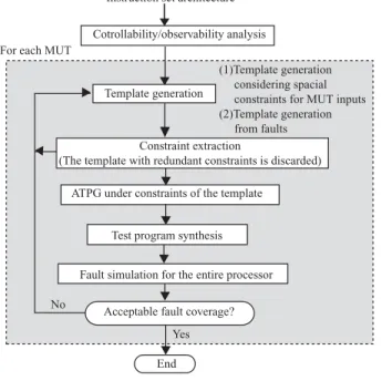
Figure 1. Overview of test program genera- tion.
with unspecified operands, which could justify some pat- terns to inputs of a MUT and propagate test responses. They use these templates to extract the constraints, and can syn- thesize test programs once operands are specified from test patterns which are generated by ATPG. However, there are some disadvantages in the method:
• Test programs may not be enough for all detectable faults at instruction level because of syntheses from only precomputed candidates of templates.
• The proposed template generation method considers only input spaces of a MUT determined by operands of one or two instructions which directly affect MUT. We propose a template based test program generation method. However, our method considers the input spaces of the MUT determined by not only operands of instruc- tions but also registers whose values depend on a series of instructions, and therefore we can obtain high fault cover- age. Furthermore, we also generate multiple templates in effective order to detect faults, which may cover different input spaces, and therefore, different detectable fault sets.
In this paper, we propose an efficient generation method of test program templates. Though possible sequences of instructions are infinite, we efficiently enumerate possible templates considering dependence of instructions each of which involves one or more data transfers between registers. Furthermore, a concept of adjacent registers is introduced, which makes it possible to consider the input spaces of the MUT determined by signals from other modules as well as signals directly from registers.
This paper is organized as follows. Section 2 is devoted to the brief explanation of our entire self testing system. We describe our method to generate templates in Section
ALU AC
SHU
SR
b_side a_side
alu_out alu_flag
DBUS
OBUS alu_code
8/
8/ 4/
8/
4/ 8/ 4/
Controller
IR
V, C, Z, N
8/
Figure 2. Parwan processor.
3, and then present experimental results and evaluate our methodology in Section 4. Finally, Section 5 concludes the paper.
2. Instruction-based self test of processors
using templates
A template is a test program in which each instruction has unspecified operands, and consists of two parts, justifi- cation and propagation.
Example 1 An example on the right in Figure 3 is a tem- plate for testing Arithmetic Logic Unit (ALU) of Parwan processor[8]. Parwan in Figure 2 is an accumulator based 8-bit processor with 23 instructions. A value is set to Ac- cumulator (AC) by instruction LDA at line 1. ADD at line 2 calculates using the content of AC, and the sum and the state flags are set to AC and Status Register (SR). SUB at line 3 applies the test pattern to ALU, and the result in AC
is observed by STA at line 4. ✷
We take a method based on templates; however, it is not practical to exhaust all of possible test program templates. We provide a two-way mechanism in which we adopt both test program syntheses from templates and template genera- tions from faults in order to guarantee efficiency and quality of test generation. We first apply ATPG with constraints ex- tracted from templates generated so as to cover large input spaces of a MUT. As the test programs synthesized from such templates are applied one by one, fault coverage be- comes difficult to go up, or it achieves required fault cov- erage. If then some faults still remain, we try to generate templates from the faults.
Figure 1 illustrates an overview of test program gener- ation. We first analyze controllability and observability of registers to select instructions for justification and observa- tion. For each MUT, some templates are generated. The constraints of MUT inputs are extracted from the template, and a test program is synthesized by filling in the operands from test patterns generated by ATPG. If the template has constraints equal to or stricter than constraints that already
LDA
ADD
SUB
1: LDA loc 2: ADD loc 3: SUB loc 4: STA loc loc : memory address Instruction dependence graph
An example of a template
Figure 3. ID-graph and a template.
used, we discard the template to avoid useless test genera- tion. As one template may not cover the whole input spaces of a MUT, we generate multiple templates. Applying this test program, we perform the fault simulation on entire pro- cessor. We repeat this process until all templates are gen- erated or fault coverage reaches a required rate. If some faults remain, templates are generated from the fault. In this paper, we only discuss how to generate template based on input spaces of a MUT.
3. Template generation
In this section, we introduce a concept of adjacent regis- ters of a MUT, and observe that there is dependence be- tween instructions caused by dataflow between registers. Overwriting value of registers should be considered. We also consider how to select instructions to justify patterns to inputs of a MUT , observe the test response from outputs of the MUT and generate multiple templates efficiently. 3. 1. Adjacent registers of MUTs
There are some registers around a MUT, and some of them connect to inputs of the MUT directly or indirectly through combinational circuits of other module, and outputs of the MUT also connect to some registers. We call them input/output adjacent registers of the MUT. Once value of such registers is justified, the test patterns can be applied to inputs of the MUT. Justifying value of input adjacent regis- ters of a MUT implies justifying value of MUT inputs, and observing value of output adjacent registers of the MUT im- plies propagation value of MUT outputs to primary outputs. A module in a datapath executes an operation capturing signals from a controller. For example of ALU in Parwan, these signals are given from a controller, and connected to Instruction Register (IR) through the controller. Hence we consider IR as an adjacent register of ALU. A concept of adjacent registers makes it possible to consider input spaces of a MUT determined by signals from a controller and IR.
Figure 4 shows an outline of our proposed method for template generation. We first select instructions to justify value of all input adjacent registers respectively. If some registers still require justifying, more instructions should be selected until source registers of instructions reach memory. We also select instructions to propagate the fault effect to memory, and append to the end of the template. As one tem- plate may not cover the whole input spaces of a MUT, we
Topological sort
A template
Justification for input adjacent registers
Justification for more registers, if necessary
Observation for output adjacent registers
More template generation
Figure 4. Outline of the template generation.
generate more templates. Our method uses IE-Graph pro- posed in [4, 5] to explore delivering route for justification and propagation. IE-Graph is a model of dataflow between registers. Nodes are registers and two special nodes, IN and OUT, which model external world such as memory and I/O devices. A directed edge between two nodes represents data transfer between registers controlled an instruction. 3. 2. Dataflow dependence between registers
We select some instructions to justify value of each reg- isters respectively. However arbitrary selections and com- binations of instructions are not always possible due to dataflow dependence between registers.
As the execution of one instruction may cause one or more data transfers between registers, it may overwrite the value of registers transferred by other instructions. We should determine the order of instructions considering about overwriting value in the registers.
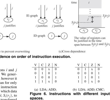
Our method use instruction dependence graph (ID- graph) modeled as dependence between instruction execu- tions. A node of ID-graph represents an execution of an instruction. The dependence between instructions is repre- sented by a directed edge of ID-graph as follows. Let us consider that we want to justify value of a register ri by an instruction i, and value of a register rj by an instruction
j.
• Dependence of dataflow:
Figure 5(a), a directed edge i in IE-graph represents that an instruction j transfers data of rito rj, which is transferred by an execution of i. There exists a directed edge from node i to node j in ID-graph.
• Dependence to prevent overwriting:
In Figure 5(b), directed edges labeled i and j in IE- graph represent that i transfers data to riand rj, j trans- fers to only rj. In this case, an execution of i must pre- cede an execution of j to prevent overwriting the value of rj. A directed edge is drawn from node i to node j in ID-graph.
(a)Dependence on dataflow (b)Dependence to prevent overwriting (c)Cross dependence
i i j
IE-graph
ID-graph i j
ri rj
i j
ID-graph i j
ri rj IE-graph
i j i j
ri rj IE-graph
i justifies j justifies i justifies j justifies
ID-graph i j
j i
ri rj
Sj(ri)
Sj(rj)
The value of registers can be justified in the time span between Sj(rj) and Sj(ri). time
Figure 5. Dependence on order of instruction execution.
• Cross overwriting:
Figure 5(c) illustrates a case that instructions i and j overwrite the value of ri and rj mutually. We gener- ally can not take such a pair of instructions; however it is possible that there is a justifiable time span for only adjacent registers where an execution of an instruction takes multiple cycles. Let Si(ri) be a state at which data is transferred to ri during the execution of i; Si(rj), to rj. And let Sj(ri) be a state at which data is transferred to ri during the execution of j; Sj(rj), to rj. We de- note that Si(ri) < Si(rj) iff a data transfer to riat state Si(ri) precedes a data transfer to rjat state Si(rj) dur- ing the execution of i. There exists a directed edge as follows.
– If Si(ri) < Si(rj),
the value of riand rjare justifiable from Si(ri) to Si(rj). The directed edge is from node j to node iin ID-graph.
– If Si(ri) ≥ Si(rj) and Sj(rj) < Sj(ri),
the value of riand rjare justifiable from Sj(rj) to Sj(ri). The directed edge is from node i to node
jin ID-graph.
Example 2 Figure 3 illustrates an example of ID-graph jus- tifying ALU inputs of Parwan. Input adjacent registers are IR, AC and SR. We first select an instruction SUB at line 3 to justify the value of IR, and next select ADD for AC and SR. In this case, ADD precedes SUB to prevent overwrit- ing the value of IR. As ADD uses the value of AC, ADD depends on LDA. LDA also precedes SUB to prevent over-
writing the value of IR. ✷
After selecting all instructions for justification, we gen- erate an instruction sequence by transforming a relation be- tween nodes of ID-graph, from a partial order to a total or- der, namely a topological sort.
3. 3. Generation of multiple templates
Input spaces of a MUT depend on instructions justifying value of input adjacent registers.
Example 3 Figure 6 shows an example of input spaces for four state flags of SR in Parwan, overflow (V), carry (C),
V C Z N V C Z N
0 0 x 0 0 1 x 0
0 1 0 1 0 0 0 1
1 0 0 1 1 1 0 1
1 1 x 0 1 0 x 0
(a) LDA; ADD; (b) LDA; ADD; CMC; Figure 6. Instructions with different input spaces.
zero (Z) and sign (N). Figure 6(a) shows the input spaces justifiable by a template LDA, ADD. Instruction ADD sets a value of V, which depends on C and N as V = C ⊕ N. However, if instruction ADD is followed by CMC which computes complements of C produces different set of input
constraints in Figure 6(b). ✷
Once we fix a template, we can easily find input spaces of a MUT where the template can justify. In general, dif- ferent template may cover different value of input spaces, and we need multiple templates to get high fault coverage. In our method, multiple templates are generated combining instruction sequences of justification which have different input spaces of a MUT and sequences of observation which propagate different errors from outputs of a MUT to pri- mary outputs.
controllability and observability
We take a method based controllability/observability of reg- isters in order to select instructions for justification and propagation and efficiently generate multiple templates. Controllability and observability are defined by the follow- ing predicates.
• Cg(i, r) : ability that instruction i can set any value to register r.
• Cpg(i, r) : ability that instruction i can set any value to a part of register r.
• Og(i, r) : ability that instruction i can observe the value of register r.
They are computed from memory to register, or register to register in a recursive manner. The Boolean value is at- tached to each edge in IE-graph respectively.
Instruction selection for justification
Instructions for justification of the adjacent registers are se- lected as follows. Let AR(m) denote the adjacent registers of the module m, MUT.
(1) Select an instruction in the descending order of the fol- lowing number:
|{r|Cg(i, r) = 1} ∩ {AR(m)}|. We try to generate templates for every instruction i with Cg(i, r) = 1 for some register r. To generate next template, we select the next instruction in the list after generating combinations of instructions by changing selected instructions in (4) and (3).
(2) For each adjacent register r with no instruction se- lected in (1), select any instruction i with Cg(i, r) = 1, if exist.
(3) For each adjacent register r with no instruction se- lected in (1) and (2), select an instruction i with Cpg(i, r) = 1, if exist. If we want to generate next tem- plate, we generate a template by changing this instruc- tion subsequent to (4).
(4) For each adjacent register r with no instruction se- lected in (1), (2) and (3), select an instruction i with Cpg(i, r) = 0, if exist. If we want to generate next tem- plate, we generate a template by changing this instruc- tion.
In (2), (3) and (4), if some candidates of instructions exist for the adjacent register, we select an instruction such that the estimated number of instruction is the least, where the estimated number of instruction is the length of the least instruction sequence to deliver a data from memory to the register. We repeat generating combinations of instructions for justification in a manner such that an instruction with less controllability is changed preceding instructions with more controllability to efficiently cover input spaces of the MUT. For example, when an instruction i with Cpg(i, ri) = 1 is selected to justify for register riand another instruction j which Cpg( j, rj) = 0 is selected for register rj, j should be permuted preceding instructions i.
After selecting instructions for all adjacent registers, if necessary, we select instructions to justify for more regis- ters. For each register r to justify, we first select an instruc- tion i with the number as follows:
max(|{r|Cg(i, r) = 1}|).
If some candidates of instructions exist for the register, we select an instruction with the least estimated number of in- struction. For each register with no instruction selected in such a way, we select an instruction in the same manner (2), (3) and (4) as adjacent registers. For example, if an instruc- tion i is selected to justify value of ri and i transfers data from rj to ri, we need select more instructions to justify value of rj.
Instruction selection for observation
After generating an instruction sequence of justification, some instructions to propagate errors to primary outputs are appended. We select instructions with Cpg(i, r) = 1 to ob-
serve the value of the register. If there are multiple output adjacent registers, a register which has an instruction with Og(i, ri) = 1 is observed prior to registers with less observ- ability. We extract the output constraints from such an in- struction selected to observe the value of an output adjacent register. Even for registers with no direct observability, we try to observe indirectly if possible. For example, the regis- ter SR of Parwan does not have any instruction that store the value of flags directly to the memory. However, we try to observe by instructions, BRAV, BRAC, BRAZ and BRAN that are branch-if-overflow, branch-if-carry, branch-if-zero and branch-if-negative, respectively.
4. Experimental results
We applied our method to ALU of Parwan processor in Figure 2. The experiments used a logic synthesis tool Design Compiler (Synopsys), test generation tool TestGen (Synopsys). Inputs of ALU are a signal alu code from con- troller, b side from a register AC and four state flags (V, C, Z and N) from SR. We treat IR as the adjacent register of ALU to justify value of alu code. Outputs from ALU is set to AC, four state flags are set to SR through Shifter Unit (SHU).
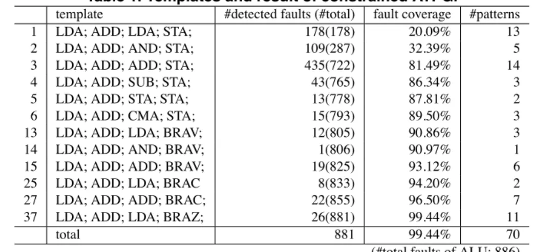
Applying our template generation, 276 templates were generated automatically to detect stuck-at faults in ALU, and 216 templates of them were discarded because they had the same constraints as some templates which had al- ready generated. As a result, we applied ATPG with 60 constraints, and 12 constraints of them contributed to detect faults. Our method achieved high fault coverage of 99.44%. The results of test generation are shown in Table 1. The templates which are generated in order of column 1 have instruction sequences in column 2. Column 3 shows the number of faults newly detected by the template, and the accumulated numbers are shown in parentheses. Column 4 shows the accumulated fault coverage. Column 5 shows the number of test patterns generated under each template. In the first template, the first instruction LDA sets value to AC, and the second ADD justifies value of AC and SR. the third LDA justifies a side from the data bus and alu code from controller. The fourth STA propagates errors to the memory.
In Table 2, the constraints of ALU inputs correspond- ing to each justification part of templates are shown from column 2 to column 8. Since the value of IR depends on instructions, the third instruction for justification of IR is changed preceding other instructions. The constraints in column 1 are expressed in fixed values which are extracted from signal alu code. For example, when alu code is jus- tified by AND in the second template, it is constrained to 000. For a side and b side, templates from the first to the fourth in which a side is justified by LDA, AND, ADD and SUB respectively, have unconstraint value. The value of V depends on C and b side[7], Z and N depend on b side jus- tified by ADD. Notice that different input spaces are coverd
Table 1. Templates and result of constrained ATPG.
template #detected faults (#total) fault coverage #patterns
1 LDA; ADD; LDA; STA; 178(178) 20.09% 13
2 LDA; ADD; AND; STA; 109(287) 32.39% 5
3 LDA; ADD; ADD; STA; 435(722) 81.49% 14
4 LDA; ADD; SUB; STA; 43(765) 86.34% 3
5 LDA; ADD; STA; STA; 13(778) 87.81% 2
6 LDA; ADD; CMA; STA; 15(793) 89.50% 3
13 LDA; ADD; LDA; BRAV; 12(805) 90.86% 3
14 LDA; ADD; AND; BRAV; 1(806) 90.97% 1
15 LDA; ADD; ADD; BRAV; 19(825) 93.12% 6
25 LDA; ADD; LDA; BRAC 8(833) 94.20% 2
27 LDA; ADD; ADD; BRAC; 22(855) 96.50% 7
37 LDA; ADD; LDA; BRAZ; 26(881) 99.44% 11
total 881 99.44% 70
(#total faults of ALU: 886)
Table 2. Input constraints extracted from templates
template input constraints
alu code a side b side V C Z N
LDA; ADD; LDA; 100 xxxxxxxx xxxxxxxx V= C ⊕ b side[7] x 1 if b side[7]
LDA; ADD; AND; 000 xxxxxxxx xxxxxxxx b side =
LDA; ADD; ADD; 101 xxxxxxxx xxxxxxxx 00000000
LDA; ADD; SUB; 111 xxxxxxxx xxxxxxxx LDA; ADD; STA; 110 b side xxxxxxxx LDA; ADD; CMA; 001 zzzzzzzz xxxxxxxx
by changing the third instruction for justification of IR pre- ceding other instructions.
5. Conclusion
This paper presented a method of template generation for instruction-based self test of processor cores. Our method constructs a test program template efficiently, considering dependence of data flow between registers. A concept of adjacent registers makes it possible to consider input spaces of a MUT determined by signals from other modules as well as signals directly non registers. Therefore, we can justify such signals in the same manner as other registers. It is also possible to consider not only the input spaces of a MUT determined operands of instructions explicitly but the input spaces whose values depend on a series of instructions. The method also generates multiple templates in effective order to detect faults, which may cover different input spaces, and therefore, different detectable fault sets. We demonstrated the effectiveness of our method using an example of Par- wan. Out of 276 templates generated for test of ALU in Par- wan, 12 templates contributed for the fault coverage. The method achieved high fault coverage of 99.44%.
Future work is developing a method to generate a tem- plate for remaining faults once fault coverage reaches given rate or the templates become difficult to raise fault cover- age. We guarantee efficiency of test generation and quality of tests.
Acknowledgments This work was supported in part by
Semiconductor Technology Academic Research Center (STARC) under the Research Project and in part by Japan Society for the Promotion of Science (JSPS) under Grants- in-Aid for Scientific Research B(2)(No. 15300018).
References
[1] S.M. Thatte and J.A. Abraham, ”Test generation for micro- processors,” IEEE Trans. on Computers, Vol. C-29, No.6, 1980, pp. 429-441.
[2] W.-C. Lai, A. Krstic, and K.-T. Cheng, ”Test program syn- thesis for path delay faults in microprocessor cores,” Proc. Int. Test Conf., 2000, pp. 1080–1089.
[3] W.-C. Lai, A. Krstic, and K.-T. Cheng, ”On testing the path delay faults of a microprocessor using its instruction Set,” Proc. 18th VLSI Test Symp., 2000, pp. 15–20.
[4] V. Singh and M. Inoue and K. Saluja and H. Fujiwara,
”Software-based delay fault testing of processor cores,” Proc. 12th Asian Test Symp., 2003, pp. 68–71.
[5] V. Singh, M. Inoue, K. Saluja and H. Fujiwara, ”Instruction- based delay fault self-testing of processor cores,” Proc. Int. Conf. VLSI Design, 2004, pp. 933–938.
[6] L. Chen and S. Dey, ”Software-based self-testing methodol- ogy for processor cores,” IEEE Trans. on CAD, vol. 20, No. 3, 2001, pp. 369–380.
[7] L. Chen, S. Ravi, A. Raghunathan, and S. Dey, ”A scalable software-based self-test methodology for programmable pro- cessors,” Proc. 40th ACM/IEEE Design Automation Conf., 2003, pp. 548–553.
[8] Z. Navabi, VHDL analysis and modeling of digital systems, McGraw-Hill, New York, 1997.