An Effective Design for Hierarchical Test Generation
Based on Strong Testability
Hideyuki Ichihara‡ Naoki Okamoto†1 Tomoo Inoue‡ Toshinori Hosokawa∗ Hideo Fujiwara∗∗
†Graduate School of Information Sciences Hiroshima City University
‡Faculty of Information Sciences Hiroshima City University {ichihara, tomoo}@im.hiroshima-cu.ac.jp
∗Department of Mathematical Information Engineering College of Industrial Technology
Nihon University [email protected]
∗∗Graduate School of Information Science Nara Institute of Science and Technology
[email protected] Abstract
Hierarchical test generation is an efficient method of test generation for VLSI circuits. In this paper, we study a test plan generation algorithm for hierarchical test based on strong testability. We propose a heuristic algorithm for find- ing a control forest requiring a small number of hold func- tions by improving an existing test plan generation algorithm based on strong testability. Experimental results show that the proposed algorithm is effective in reducing additional hold functions, i.e., reducing hardware overhead and delay penalty of datapaths.
Keywords. Hierarchical test generation, strong testability, datapath, test plan.
1. Introduction
Hierarchical test generation [1] refers to precomputing test sets for all of modules and justifying these test sets (test plan generation) at register-transfer level (RTL). This hierarchical test generation has several advantages over the full scandesign-for-testability (DFT) method [2], which is widely applied to today’s designs. One is, not only the mod- ules for which test sets are computed are relatively small compared to the whole circuit, but also if a module is the same as another, its test set can be shared with the other, and hence the computation time becomes small. Second, since the number of modules in an RTL circuit is smaller than that of logic gates that implement the modules, the computation time for the RTL justification (or test plan generation) can be reduced. Another advantage is the test application time. The test patterns to the modules are justified by using exist- ing datapaths, and accordingly multiple bits are propagated in parallel on the datapath. Moreover, this test generation method is fit for today’s VLSI design style such that design- ers describe circuits at RTL and derive logic level circuits by using logic synthesis.
However, the test plan generation is still an intractable problem as well as test generation for logic circuits, and therefore some circuits require large computation time for it. In order to solve it, several literatures presented design for hierarchical test generation and high-level synthesis for hierarchical test generation [3]-[7].
Wada et al. proposed strong testability [3] which is a prop-
1He is currently with Sony LSI Design Inc. Kanagawa, Japan.
erty of datapaths for which test plans can be generated effi- ciently. If a datapath is strongly testable, its test plans can be generated independent of the precomputed test sets and their responses. Moreover, [3] presented an algorithm for generat- ing test plans and determining DFTs. The algorithm (called previousalgorithm here), however, was considered by giving priority to reducing its time complexity, and consequently ad- ditional hardware overhead tends to increase. Furthermore, the algorithm imposes a rigid condition concerning datapath structure, and hence, in order to apply it to practical circuits, further DFT overhead is required to satisfy the condition.
In this paper, we consider an improvement of the previous algorithm [3], which generates test plans and DFT for RTL datapaths based on strong testability. We focus on the con- trol forestgeneration algorithm, which is a part of the pre- vious algorithm, and improve it so that the number of hold functions in the generated control forest is reduced. First, we propose a heuristic algorithm for reducing the number of conflicts(the tail (primary input) of the path to an input of a module is identical to that of another input of the mod- ule, and their sequential depths are the same). The reduc- tion of conflicts can decrease the number of hold functions required to avoid the conflicts. Furthermore, by expressing reconvergent paths without registers as strong conflict, the proposed algorithm can find proper control paths, even if given datapaths do not satisfy the above-mentioned condi- tion for the previous algorithm. Next, we show an optional modification of the proposed heuristic algorithm so that the number of hold functions is more reduced by sharing hold functions. Sharing hold functions with as many conflicts as possible can reduce the number of hold functions required in the control forest. Experimental results show that the pro- posed algorithm is effective in reducing additional hold func- tions, which contributes the reduction of hardware overhead and delay penalty of datapaths.
The remaining of this paper is organized as follows. Sect. 2 introduces the previous algorithm based on strong testabil- ity. Sect. 3 proposes our heuristic algorithm, which is for re- ducing conflicts, avoiding improper control paths, and shar- ing hold functions. Sect. 4 shows some experimental results, and Sect. 5 concludes this paper.
IEEE the 14th Asian Test Symposium (ATS'05), pp. 288-293, Dec. 2005.
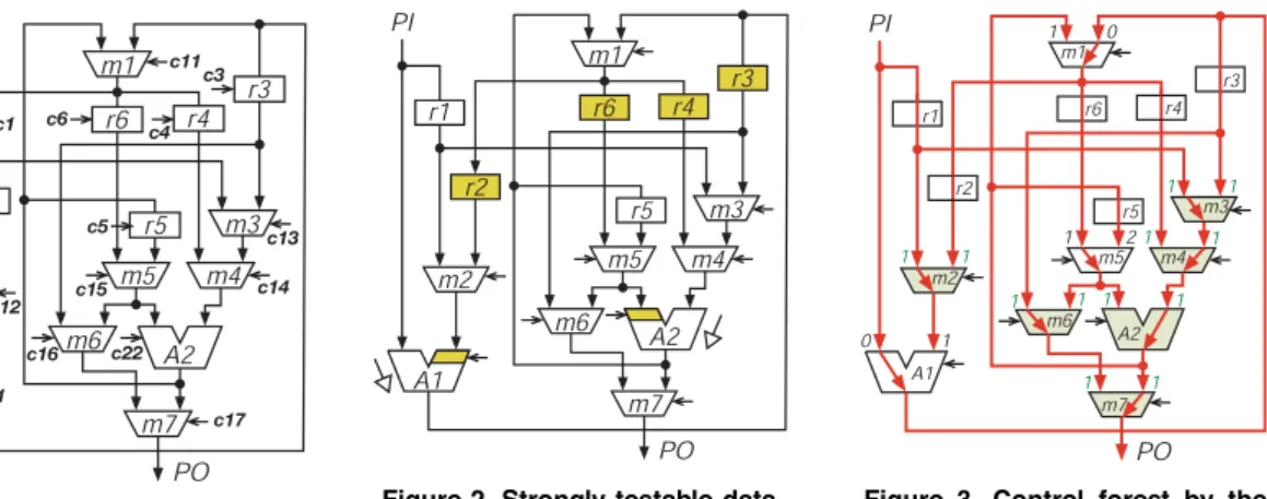
Figure 1. Sample datapath. Figure 2. Strongly testable data- path with DFT.
Figure 3. Control forest by the previous algorithm.
2. DFT based on strong testability
Hierarchical test generation [1] for an RTL datapath con- sists mainly of two steps. In the first step, a test-pattern for each module (or element) composing the datapath is gener- ated. Here, modules under the test generation in the first step are assumed to be combinational circuits, e.g., operational units (adders and multipliers) and multiplexers (MUXs). In the second step, for each module, the test-pattern generated in the first step and its response are justified, i.e., a test plan referring to a sequence of control signals that propagate the test-pattern from a primary input to the module and its re- sponse from the output of the module to a primary output.
Hierarchical test generation is a divide-and-conquer ap- proach, and hence test generation for large circuits can be performed efficiently. However, test plan generation may consume much time for large datapaths. Strong testability [3] refers to a property of a datapath for which test plans can be generated efficiently independent of test-patterns obtained in the first step.
A datapath is said to be strongly testable if, for every module, the datapath satisfies the following two conditions: strong controllability and strong observability. The former is that any value can be propagated to each input of the module from a primary input and the latter is that any value of the output of the module can be propagated to a primary output. We can achieve 100% fault efficiency for a strongly testable datapath with a complete test set for each module.
In [3], the authors presented an algorithm (called the pre- viousalgorithm hereafter) for making a given RTL datapath strongly testable and for generating test plans for the strongly testable datapath. The algorithm consists mainly of the fol- lowing three steps. (1) Generating a control forest: A control path from a primary input to each input of every module is determined. (2) Generating an observation forest: An ob- servation path from the output of every module to a primary output is determined. (3) Determining DFT circuits: DFT circuits that implement the above-mentioned control and ob- servation forests are inserted to the datapath.
DFT circuits achieve: (1) Hold function for a register: it can retain a value of the register during arbitrary clock cy- cles, and (2) Thru function for a module: it can propagate a
value of an input to the output independent of values on the other inputs. Fig. 2 is a strongly testable datapath obtained by applying appropriate DFT circuits to the datapath in Fig. 1. In this figure, hold functions are added to registers r2, r3, r4 and r6, and two thrus are added to the left and right inputs of modules A1 and A2, respectively.
The previous algorithm does not generate a test plan for each module, but generates control and observation paths that are common to all the modules in the datapath, and hence the computation time can be reduced.
2.1. Control forest generation algorithm
This paper focuses on an algorithm for generating control forest, and hence we here give a brief explanation of the al- gorithm in the previous method. The previous control forest generation algorithm determines a path to each input of ev- ery module from a primary input (and as a result, a set of trees consisting of control paths, i.e., a forest is obtained.) A path from a primary input to an input of a module is im- plemented by adding thrus to the modules on the path. The algorithm performs based on breadth-first search in terms of sequential depth (the number of registers on a path), so that the sequential depth of control paths becomes small, i.e., it is a heuristic that aims to reduce the length (or test applica- tion time) of test plans. The breadth-first algorithm expands a search space from a register (or a primary input) to next (reachable) registers at one step.
Fig. 3 shows a control forest obtained by the previous al- gorithm for the datapath in Fig. 1. Note that this control for- est results in the DFT circuits shown in Fig. 2. The digit on an input of a module denotes the sequential depth from a pri- mary input on the control forest, and it corresponds to the number of clock cycles required to propagate a test-pattern to the input from the primary input. When for a module, the start primary input of the path to an input of the module is the same as that of another input, and the sequential depth of the path is equal to that of the other input in the control forest, different values cannot be applied to the two inputs of the module simultaneously. Such paths (and the module with the paths) are said to be conflicting. For example, modules m2, m3, m4, m6, m7 and A2 in Fig. 3 are conflicting. When a conflict occurs, at the third step of the (above-mentioned)
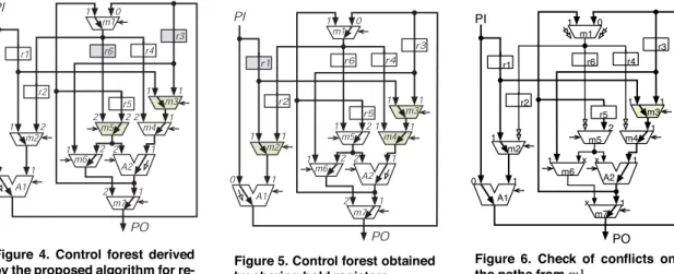
Figure 4. Control forest derived by the proposed algorithm for re- ducing conflicts.
Figure 5. Control forest obtained by sharing hold registers.
PI
PO
2
0
0
1 1
1
1
1 1
1
1
x x x 1
A1
A2 m2
m4 m3
m5 m1
m6
m7
r1 r6
r5
r3
r2
r4
Figure 6. Check of conflicts on the paths fromm1.
previous algorithm, a hold is added to a register on either of the two paths. As a result, different values can be applied to two inputs of the module from an identical primary input. In Fig. 3, the additional hold functions to registers r2, r3, r4 and r6 solve the conflicts for modules m2, m3, m4, m6, m7 and A2. For example, the conflict at module m2 is solved by the hold function for register r2. First, a test-pattern for the right input of module m2 is loaded into register r2 along the path
"PI,A1,m1,m2# and register r2 is held, next a test-pattern for the left input of module m2 is loaded into register r1 from PI. 3. Heuristic algorithm for reducing hold functions
The previous DFT and test plan generation algorithm is effective and efficient for hierarchical test generation. The hardware overhead, however, is not always small, e.g., the control forests in Figures 4 and 5 require only two and one extra hold functions in the paths, respectively, while the con- trol forest in Fig. 3 requires four hold functions.
Since the previous algorithm searches control paths ac- cording to sequential depth based on breadth-first search, it has a potential for frequent occurrence of conflicts. Conse- quently, additional hold functions result in excess. Here we consider a heuristic algorithm for generating a control forest without conflicts by improving the previous algorithm while keeping its efficiency.
3.1. Basic heuristic algorithm
The proposed algorithm is basically a breadth-first search algorithm based on sequential depth without backtracking, as well as [3]. When determining a thru from an input to the output of a module, it checks the conflicts that result from the thru. Note that the previous method determines thrus without any condition or checking. If a thru (a path from an input to the output) of a module results in no conflict at the modules connected from the module, it is determined. Otherwise, the thru is not determined at this time because another thru from a different input of the module may have no conflict in the subsequent search. If a module has no input without con- flict, it selects the thru from the input such that the number of conflicts resulting from its thru is minimum.
[Heuristic algorithm for reducing conflicts]
1 Append all the inputs of all the modules connected from primary inputs to queues que reg and que wire. 2 Take out an input e from que wire (if que wire is empty,
from que reg). If either queue is empty, go to Step 4. 3 Let v be the module whose input is e. Check whether
the thru from e to the output of v causes a conflict at the modules u1,u2, ...connected from v (through some registers). Suppose a module uiwhich is connected from vwith an input e$. If the path from a primary input to another input e$$of uiis not determined, the conflict of e$$ is regarded as don’t-care, and hence it is considered that e$is not conflicting with e$$.
(a) If there is no conflict, the thru from e is determined, and append all the inputs connected from the output of v to que reg and que wire.
(b) Otherwise, if all the inputs of module v are checked, and if every input of module v results in conflict, then (1) select the thru from the input such that the number of conflicts that occur at the modules con- nected from v is minimum. Or else, (2) append mod- ule v to a queue que suspend.
Then, go to Step 2.
4 If que suspend is empty, the algorithm terminates. Oth- erwise, take out a module v from que suspend. If a thru of module v is not determined, let e be an input with the minimum number of conflicts, and go to Step 3. ! This algorithm searches paths in breadth-first by means of two queues que wire and que reg. At one step, it searches a path from an input (e) of a module (or a primary input) to an input (e$) of another module that are connected from the module. If the path(e,e$) has no register, the head e$is appended to que wire, or else e$is appended to que reg.
We explain the algorithm using Fig. 1. There are three modules A1, m2 and m3 that are reachable from a primary input PI. Since the path to A1 from PI has no register, the left input of A1 is appended to queue que wire, while the left inputs of m2 and m3 are appended to queue que reg since the paths to m2 and m3 from PI have registers (Step 1). The algorithm processes que wire first, and hence the left input
PI r2
PO1 PO2
r1
A1
1 1 1 1
A3 A2
PI r2
PO1 PO2
r1
A1
1 1 1 1
A3 A2
m1 r3 PI
r2
PO1 PO2
r1
A1
1 1 1 2
A2 A3
(a) (b) (c)
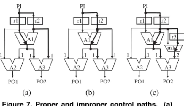
Figure 7. Proper and improper control paths. (a) Thru from the left at A1 (proper). (b) Thru from the right at A1 (improper). (c) Proper by inserting a bypass register.
of module A1 is taken out from que wire (Step 2). Next, to determine the thru from the left input to the output of A1, it checks the conflicts that occur at the inputs of modules that are reachable (or adjacent) from A1 (Step 3). In this example, there are three modules m1, m3 and m6 that are reachable from module A1, and the inputs of module m3 are conflicting. Consequently, the thru from the right input of A1 to the output is not determined, and then module A1 is appended to que suspend (Step 3-(b)-(2)). After backing to Step 2, since que wire becomes empty, module m2 or m3 is taken our from que reg and the process continues.
In a subsequent process, a situation where all inputs of a module are checked and every input of the module results in conflict arises (Step 3-(b)). Fig. 6 shows the situation for module m1. In this example, since both inputs of m1 are conflicting, we select the thru from the input such that the number of conflicts that occur at the modules connected from m1 is minimum (Step 3-(b)-(1)). If the left input of m1 is selected, one conflict occurs at module m5. If the right input of m1 is selected, on the other hand, the number of conflicts becomes two. Consequently, the left input to the output of m1 is selected as shown in Fig. 4.
When both queues que wire and que reg become empty, a module v at which a thru is suspended due to conflict is taken out from que suspend, and then the inputs of the modules that are connected from module v are appended to que wire and que reg (Step 4).
3.2. Avoiding improper control paths
In order to ensure a solution (or the test plans for all the modules), in [3], the previous method forces a given datapath to satisfy the following conditions.
Condition(Independent registers on reconvergent paths): For any pair of reconvergent paths, either path has its own register, which is not on the other path. For example, two reconvergent paths from PI to A1 exist in Fig. 1, and the right path has a register r1, which is not on the other path.!
In general, a datapath does not always satisfy this condi- tion, i.e., for any pair of reconvergent paths, either path has its own register. However, even if a datapath does not satisfy the condition, the previous algorithm can happen to generate a proper control forest for such a datapath (because the con- dition is sufficient for generating test plan generation). Here we consider a heuristic for generating a proper control forest
for such a general datapath (i.e., avoiding an improper con- trol forest that includes a pair of reconvergent paths such that neither path has it own register).
Fig. 7 shows an example of cases where either of recon- vergent paths from PI to A3 in a control forest has its own register or not. In either case of (a) and (b), two conflicts oc- cur at the inputs of A2 and A3. In case (a), the path from PI to the left input of A3 has its own register r1, which is not on the other path to the right input. On the other hand, in case (b), either of paths to the left and right inputs of A3 does not have its own register, and therefore A3 cannot be tested by the control forest. If we are obliged to use this control paths for testing A3, extra DFT overhead is required, e.g. insertion of a bypass register to either path, as shown in Fig. 7 (c).
In order to find such testable control paths, in our algo- rithm, the number of conflicts by a reconvergent path without its own register is regard as extremely large (e.g., a constant which is larger than the total number of modules), so that such improper paths as shown in Fig. 7 (b) are not selected. This path selection is performed by the minimum conflict thru selection at Step 3(b)-(1)).
3.3. Sharing hold registers
When a module is conflicting, the authors of [3] adopt a rule that a hold function is added to a register directly con- necting to the conflicting module. For example, when this rule is applied to the control forest shown in Fig. 4, which is derived by the above proposed algorithm, register r6 and r3 are severally required to have hold functions by conflicting modules m5 and m3.
In general, there exists a case where one hold function re- solves several conflicts, i.e., one hold register is shared with several conflicting modules. Hence, generating a control for- est such that a hold function can be shared with several con- flicting modules, we can reduce the number of hold registers. For example, if we obtain the control forest in Fig. 5, the three conflicting modules are resolved by hold register r1.
To generate a control forest such that a hold register is shared with as many conflicting modules as possible, we con- sider an optional modification on the proposed heuristic al- gorithm shown in Sect. 3.1.
Fig. 6 shows a situation where the thru of module m1 is about to be determined during the process of the proposed algorithm, provided that register r1 has already been decided as hold register. Note that this situation occurs at Step 3-(b) of the proposed algorithm. In this situation, we estimate the number of extra hold registers, instead of the number of con- flicting modules for the proposed algorithm shown in Sect. 3.1, for selecting each thru. If the thru from the right input is selected, the conflicting modules are m2 and m4. To resolve each conflict, module m2 requires a hold function at register r1 or r2 while module m4 requires a hold function at register r1 or r4. As a result, one register, r1, is selected as a hold register by resolving both conflicting modules. Since regis- ter r1 has already been a hold register, no extra hold register is needed when the right thru is selected. Consequently, the algorithm selects the thru from the right input to the output of module m1. The resultant control forest is shown in Fig. 5. Note that the algorithm, described in Sect. 3.1, for selecting thrus based on the number of conflicts selects the left input
Table 1. Benchmark datapaths. circuits #PIs #POs #MUXs #ops. #regs.
GCD 2 1 4 4 3
4thIIR 1 1 3 5 12
PAULIN 2 2 11 4 7
DP1 1 1 7 2 6
LWF1 1 1 6 3 3
LWF2 2 2 5 3 5
JWF1 1 1 25 3 14
JWF2 5 5 25 3 14
RISC 1 3 92 16 40
DCT-F 4 7 26 40 11
of m1, as mentioned above.
At the following third step (determining DFT circuits and generating test plans for all modules), the algorithm deter- mines hold functions at registers shared by as many conflict- ing modules as possible, instead of registers directly connect- ing to conflicting modules[3].
4. Experimental Results
We implemented the proposed algorithm for generating control forests, and applied it to benchmark datapaths shown in Table 1. In this table, Columns ’#PIs’, ’#POs’, ’#MUXs’,
’#ops.’ and ’#regs.’ denote the numbers of primary inputs, primary outputs, multiplexers, operational units and registers in each datapath, respectively. Note that all the benchmarks except GCD, 4thIIR and PAULIN do not satisfy the condi- tion shown in Sect. 3.2, i.e., these have some pairs of recon- vergent paths such that either of the paths does not have its own register.
Table 2 shows the experimental results. In this table, Row
’[3]’ denotes the results obtained by the previous algorithm for control forests. Rows ’ours’ and ’ours+’ show the re- sults obtained by the proposed algorithm without and with the modification shown in Sect. 3.3, respectively. Note that the avoidance of improper control path in Sect. 3.2 is always used. In ’ours’, the algorithms for generating an observation forest and determining DFT circuits are the same as those in [3], while, in ’ours+’, only the algorithm for generating an observation forest is the same as that in [3]. Note that the CPU time for the proposed method is almost the same as that for the previous one, and the time for each detapath is less than one second on a PC (PowerPC G4, 1.5GHz).
In Table 2, Columns ’c’ and ’o’ under ’#cf.’ denote the numbers of conflicts required by a control forest and by an observation forest for each datapath, respectively, and Columns ’c”, ’o’ and ’sum’ under ’#holds’ denote the num- bers of hold functions inserted for a control forest and for an observation forest, and then the total number of hold func- tions, respectively. Column ’#untests’ reports the number of modules that are untestable due to improper control paths. At the last column in this table, the sum of the length of test plans for all the modules is shown. Note that the test applica- tion time is the sum of the product of the length of test plans and the number of test-patterns for each module.
As shown in this table, our proposed heuristic algorithm reduces the number of conflicts in the control forests, and consequently reduces the total number of additional hold functions for all the benchmarks. Reduction in the total num- ber of additional hold functions has an impact on not only reducing hardware overhead of a datapath but also reducing
Table 2. Conflicts and hold functions
#cf. #holds #un- plan
circuits method c o c o s test len.
[3] 0 0 0 0 0 0 26
GCD ours 0 0 0 0 0 0 26
ours+ 0 0 0 0 0 0 26
[3] 1 2 1 1 1 0 62
4thIIR ours 0 1 0 1 1 0 62
ours+ 0 1 0 1 1 0 62
[3] 2 0 2 0 2 0 69
PAULIN ours 1 0 1 0 1 0 68
ours+ 1 0 1 0 1 0 68
[3] 6 2 4 2 4 0 30
DP1 ours 2 0 2 0 2 0 29
ours+ 3 0 1 0 1 0 28
[3] 2 1 1 1 1 0 33
LWF1 ours 0 2 0 1 1 0 34
ours+ 0 2 0 1 1 0 34
[3] 1 1 1 1 1 0 27
LWF2 ours 1 1 1 1 1 0 27
ours+ 1 1 1 1 1 0 27
[3] 13 10 8 2 8 0 136
JWF1 ours 5 2 5 2 7 0 141
ours+ 7 2 1 2 3 0 148
[3] 4 0 4 0 4 0 92
JWF2 ours 0 0 0 0 0 0 92
ours+ 0 0 0 0 0 0 92
[3] 83 32 44 25 44 7 353
RISC ours 67 0 36 0 36 2 317
ours+ 67 0 19 0 19 2 317
[3] 4 0 3 0 3 2 168
DCT-F ours 2 0 2 0 2 2 166
ours+ 2 0 2 0 2 2 166
the delay (performance) penalty of it. Moreover, comparing our two algorithms ’ours’ and ’ours+’, for DP1, JWF1 and RISC, the number of additional hold functions for ’ours+’ is smaller than that for ’ours’, whereas the number of conflicts for ’ours+’ is equal to or larger than that for ’ours’. Thus, this optional modification for sharing hold registers is effec- tive for reducing both hardware overhead and performance penalty of a datapath.
As shown in Column ’#untests’, although benchmarks ex- cept GCD, 4thIIR and PAULIN do not satisfy the condition in Sect. 3.2(concerned with reconvergent paths), both of the previous and proposed method could find proper solutions, i.e., Column ”#untests” is zero, for five benchmarks DP1, LWF1, LWF2, JWF1 and JWF2. Unfortunately, the pro- posed methods as well as the previous one cannot find proper control paths for RISC and DCT-F, however, the number of untested modules in RISC can be reduced by the proposed methods. From these results we can consider that our heuris- tics concerned with reconvergent paths is also effective in avoidance of improper control paths. Note that the number of untested modules corresponds to the number of bypass registers required for making the resultant control paths ap- plicable, and accordingly its reduction has large impact on hardware overhead of datapaths. Furthermore, especially for RISC, the proposed algorithm can reduce the the total length of the test plans, as shown in Column ’plan len.’.
Table 3 shows hardware overhead for test plan generation. We assumed that a test controller is inserted between a data- path and a controller, as shown in Fig. 8, which is based on [4]. We checked the area size of the shaded parts: a plan gen- erator and a multiplexer T-MUX for switching normal mode
controller datapath test controller
ctr. TPG (comb.)
T-MUX test 1 0 plan generator TPR
PIs
POs mod
pat PIs
POs test
TMR
Figure 8. Test controller.
and test mode. This is because only the size of these parts directly depends on the DFT circuits inserted into a datapath. The plan generator, which can generate a test plan for a mod- ule specified by signal mod with a test-pattern specified by pat, is a counter-based FSM and it consists of a counter (ctr.) and a combinational circuits (TPG).
In Table 3, Column ’ctr.’ denotes a size of the counter, and the columns under ’Area’ denote the area size of TPG, T-MUX and the sum of them (total). TPG and T-MUX were designed by HDL and synthesized by Synopsys Design Com- piler, and then the area sizes of them are calculated provided that the area size of an inverter is one, From Table 3, we can see that the counters of the plan generator require the same size for all the methods. Comparing the are size of TPG and T-MUX, the area size of the proposed method is equal to or smaller than that of the previous method for all circuits ex- cept for LWF1 and DCT-F. Especially for DP1, JWF2 and RISC, the proposed method is effective because it can re- duce the number of hold functions controlled by the test plan generator, as shown in Table 2. Unfortunately, for 4thIIR, LWF2, JWF1, RISC, the are size of TPG and T-MUX for
’ours+’ is larger than that for ’ours’ owing to the increase in the size of the plan generator. This is because sharing hold registers makes the control for hold registers complicated, even though it is effective to reduce hardware overhead and delay penalty of datapaths.
5. Conclusions
In this paper, we considered an improvement of an al- gorithm of test plan generation and DFT for RTL datapaths based on strong testability. We focused on the control forest generation algorithm that is a part of the previous test plan generation algorithm, and improved so as to (1) reduce he number of conflicts requiring hold functions in the generated control forest, (2) find control paths that require no (i.e., the paths are proper) or small number of extra DFTs such as by- pass registers, even if given datapaths do not satisfy a condi- tion for the previous algorithm, and (3) share a hold register among as many conflicting modules as possible. Experimen- tal results show that the proposed algorithm, including the optional modification, is effective in reducing additional hold functions for strongly testable datapaths. This is effective in reducing the hardware overhead and the delay penalty of a datapath, as well as the hardware overhead for generating test plans.
Table 3. Overhead for test plan generation.
ctr. Area
circuits method [bit] TPG T-MUX total
[3] 3 7 24 31
GCD ours 3 7 24 31
ours+ 3 7 24 31
[3] 4 61 161 222
4thIIR ours 4 49 161 210
ours+ 4 61 161 222
[3] 3 121 70 191
PAULIN ours 3 107 66 173
ours+ 3 107 66 173
[3] 2 68 59 127
DP1 ours 2 74 56 130
ours+ 2 46 51 97
[3] 3 80 43 123
LWF1 ours 3 87 43 130
ours+ 3 87 43 130
[3] 3 33 31 64
LWF2 ours 3 33 31 64
ours+ 3 51 31 82
[3] 3 311 181 492
JWF1 ours 3 306 177 483
ours+ 3 376 157 533
[3] 3 261 173 434
JWF2 ours 3 231 149 380
ours+ 3 231 149 380
[3] 3 977 735 1712
RISC ours 3 750 720 1470
ours+ 3 834 652 1486
[3] 3 452 171 452
DCT-F ours 3 470 167 470
ours+ 3 470 167 470
Acknowledgments
Authors would like to thank Masahide Miyazaki (STARC), Michiko Inoue, Satoshi Ohtake and Tomokazu Yoneda (NAIST). Authors are also grateful to Tomoya Hirao, Shigenori Matsuo, Seiji Hamamoto and Koei Yamada (Sys- tem JD) for their cooperation in making experiments. This work was supported in part by Hiroshima City University un- der the HCU Grant for Special Academic Research. References
[1] B. T. Murray and J. P. Hayes, ”Hierarchical test generation using pre-computed tests for modules,” IEEE Trans. CAD, vol.9, no.6, pp.594–603, June 1990.
[2] M. Abramovici, M. A. Breuer and A. D. Friedman, Digital Sys- tems Testing and Testable Design, pp. 441–447, IEEE Press, 1990.
[3] H. Wada, T. Masuzawa, K. K. Saluja and H. Fujiwara, ”Design for strong testability of RTL data paths to provide complete fault efficiency,” Proc. VLSI Design, pp.300-305, Jan. 2000. [4] S. Ohtake, S. Nagai, H. Wada and H. Fujiwara, ”A DFT method
for RTL circuits to achieve complete fault efficiency based on fixed-control testability,” Proc. ASP-DAC, pp.331-334, 2001. [5] S. Bhatia and N. K. Jha, ”Genesis: A behavioral synthesis sys-
tem for hierarchical testability,” Proc. EDTC, pp. 272-276, 1994.
[6] I. Ghosh, A. Raghunath and N. K. Jha, ”Design for hierarchi- cal testability of RTL circuit obtained by behavioral synthesis,” Proc. ICCD, pp.173-179, 1995.
[7] I. Ghosh, A. Raghunath and N. K. Jha, ”A design for testability technique for RTL circuits using control/dataflow extraction,” Proc. ICCAD, pp.329-336, 1996.
![Table 2 shows the experimental results. In this table, Row ’[3]’ denotes the results obtained by the previous algorithm for control forests](https://thumb-ap.123doks.com/thumbv2/123deta/5752976.27072/5.892.144.411.176.341/experimental-results-denotes-results-obtained-previous-algorithm-control.webp)
![Table 3. Overhead for test plan generation. ctr. Area circuits method [bit] TPG T-MUX total](https://thumb-ap.123doks.com/thumbv2/123deta/5752976.27072/6.892.475.752.191.568/table-overhead-test-generation-area-circuits-method-total.webp)
