Feedback Control of Traffic Signal Network of Less
Traffic Sensors by Help of Machine Learning
Takumi WAKAHARA
Graduate School of System Information Sciences Future University Hakodate
Hakodate, Japan g3107007@fun.ac.jp
Sadayoshi MIKAMI
Department of Complex and Intelligent Systems Future University Hakodate
Hakodate, Japan s_mikami@fun.ac.jp
Abstract— As a way of resolving vehicle congestion, there is a feedback control approach which models a traffic network as a discrete dynamical system and derives feedback gain for controlling green light times of each junction. Since the input is the sensory observed traffic flow of each link, and since the state equation models both the topology and the parameters of the network, it is effective for adaptive control of a wide area traffic in real-time. One of the essential factors in a state equation is the vehicles’ turning ratio at each junction. However, in a normal traffic sensor layout, it is impossible to directly measure this value in real-time, and values from traffic census are used. This paper is to propose a method that predicts this value in real-time through machine learning and gives more appropriate feedback control. Out idea is to find the turning ratio through probabilistic search by Reinforcement Learning referring to the degree of improvement of the entire traffic flow. At this moment we have finished formulation of the scheme and the verification for the performance by a traffic simulator is on the way.
Keywords-component; Reinforcement Learning, Traffic light Control, Feedback Control, Discrete Dynamical Syste, Split
I. INTRODUCTION
It is desired for modern urban transport to control traffic lights in a wide area in real-time according to sensory observed parameters such as traffic flows and queue lengths [3]-[5]. However, the number and the variations of traffic sensors are usually very limited in an urban road network, and it is also difficult to put many new sensors in a network by the reasons of cost and construction problems etc.
Our approach is to apply Machine Learning to estimate values of current traffic properties that are important but are not being able to measure by current sensor layouts. The approach is linked with a feedback based traffic network control [1][2].
From the next chapter, firstly we describe the background of the current traffic light control methods and why we focus on the feedback approaches. Secondly, we describe the formulation of the feedback based traffic control method which we rely on. Finally, we show the scheme of the Reinforcement Learning based approach to estimate the missing traffic properties and improve the entire traffic flow based on a current traffic flow measurements.
II. TRAFFIC LIGHTS CONTROL FOR URBAN TRAFFIC
NETWORK
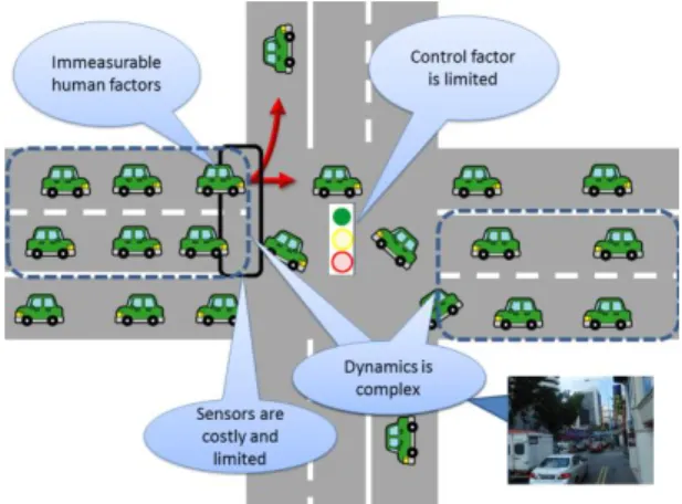
The traffic control problem is highly complex. There are many reasons for this complexity such as: (1) Controllable factors, such as split, cycle, and offset, are limited and influence multiple roads at a time; (2) Dynamics is complex. One junction’s traffic is affected by the traffic of many other areas, and delay time is large; (3) Immeasurable human factors exist. Driver's hidden intention affects the flow. But this is not measured in advance; (4) Sensors are costly and limited. A vehicle detector is usually used. But it measures only current flow at a pinpoint location.
One of the key points to deal with these is to realize adaptive light control. SCOOT [3], SCATS [4], and MODERATO [5] systems are well known. These are based on an idea of measuring a degree of traffic flow passing through a junction and controlling light parameters accordingly. Although these are effective and practically used in many cities, some parameters are relying on human design. More importantly, coordinated adaptive controls between multiple traffic lights are not considered. Only considered is an offset, which is a time shift of light phases between two adjacent junctions. But major control factors such as split (green time ratio) and cycle time (one cycle of traffic lights for a junction) are not well considered.
Recently, some approaches from control theory sides are taking attention [1][2]. Applying the notion of optimization and stability gives rigid control. Also the approach provides control scheme over multiple junctions.
The method is based on a "store and forward" method [9], which models traffic network as a discrete time dynamical system in terms of inflow and outflow. Characteristics of traffic flow at each junction are represented by some factors such as a rate of cars turning to each direction. By formulating the traffic as a discrete dynamical system, the approach applies feedback control to control split by the flow rate of each road. In the papers [1] [2], they derive feedback control gain directly by using optimal control methods such as the LQ optimization methodology.
This approach is both theoretically and practically useful and is used in some cities. But there are still some parameters that human should carefully predetermine.
One of the biggest parameters that are essential for modeling but is difficult to measure is a turning ratio. This is the rate of cars that turns to each direction, and thus contains human factors, which is not able to measure by sensors. Since the rate describes the key structure of a junction, its accuracy affects the feedback performance.
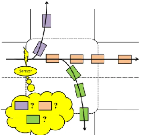
However, this factor is difficult to monitor in real time. One reason is that, as in Fig.2., a traffic sensors allocated at the inward of the junction cannot separate either the coming car is from left or right.Another is that, although a sensor is allocated at a turning lane, the lane is often used both right turn and straight traffic, and cannot derive pure right turning traffic. Also in a near saturated situation, where queue is reaching to the next junction, potential demand for turning is not measured because of the blockage, and model parameters are wrongly estimated.
This paper aims at providing a machine learning approach to estimate turning ratio from observation of traffic flow, by which traffic lights control that properly reflects the current situation will be realized.
Because exact turning ratio is not measurable in real-time, any methods that needs training data are not applicable. However, it is said that the traffic flow will be improved if the
feedback controller uses more exact model, that is, more exact turning ratio values. It results in a combinatorial search for a set of turning ratios that will improve the traffic flow, and this is done by Reinforcement Learning (RL) [6].
In this paper, the notion of feedback control of traffic lights by discrete dynamical systems modeling is first introduced, and the design of learning systems to predict the parameters of the model is described in detail.
III. TRAFFIC MODEL
A. Road network configuration[1]
A condition of traffic in a lane is described by a traffic flow [pcu/h], where pcu is a passenger-car-unit which is intended to count the number of cars in terms of standard car size. For example, a bus would be counted as 2 or 3 pcu. A maximum flow rate that is able to pass through a road (lane) is called a
saturated flow [pcu/h].
Traffic network is represented as a directed graph. Fig.4. shows an example of simple two-junctions-one-way configuration. Each road is described as a link with it traffic flow . At a junction, link is connected to the other links { } where is a set of indexes of outgoing links. Also { } are a set of links from incoming direction and is its indexes. Each car arriving at a junction will go to the next link at a certain probability. We call it as a turning
ratio , which denotes a rate of flow from link i to j. denotes a saturated flow for the link i.
Traffic lights at a junction controls flow from one link to the other. A type of traffic light is called a phase. For major 4 roads junction there are usually 4 phases: allowing all forwarding traffic (phase 1 and 3), and right turn and straight through only (2 and 4), where phases 1 and 2 are for horizontal traffic in Fig.4. These phases rotate cyclically, and the duration is called a cycle time. A ratio of green light for phase i at junction m is called a split . Difference of cycle start time
between two adjacent intersections is called an offset. It plays a role to allow vehicles departing from one junction not to be stopped by another junction.
Figure 3. Road network Configuration
Figure 2. Situations where turning rate is not measured by
B. Discrete dynamical systems model of traffic flow[1][2]
Assume that all the lights in consideration are controlled by the same cycle time T, and that the offset is set to zero. Traffic flow for a link i is formulated by the difference of incoming flow and outgoing flow, which is written as:
( ) ( ) ( ) ( ) (1) where ( ) is an inflow and ( ) is an outflow, and k denotes that the values are at k-th cycle. Outflow is affected by traffic lights. In a near saturated situation, the outflow ( ) is proportional to the cumulative green times of the lights that controls outward traffic of the link i. Therefore, the outflow is described as ( ) ∑ . Note that sideways without
traffic light control are omitted.
Inflow is also affected by green time of the traffic lights located at an incoming junction. For each link { }, traffic flow going to the link i is proportional to the turning ratio from m to i. By considering the green time for the flow from m to i, the inflow ( ) is described as:
( ) ∑ (2)
where gives a phase number for the junction m that affects
flow from the link j to i.
IV. FEEDBACK CONTROL OF TRAFFIC LIGHTS
The above linear discrete dynamical system of traffic flow allows the application of feedback control of the traffic lights. To begin with, the targeting traffic flow should be specified. We assume that the traffic flow will be balanced under a steady traffic demand by an appropriate traffic light control. We denote this equilibrium flow as . The nominal green time
should also be assumed. By describing ( ) ( ) and ( ) ( ) , a state equation for traffic is
derived as:
( ) ( ) ( ) (3)
where x, u are the vector representations of , and B is a
matrix which includes traffic network configuration factors such as saturated flow and turning ratio.
For this state equation, the LQ-optimal control problem is able to be applied, which derives the feedback gain K for the following feedback scheme [1]:
( ) ( ) (4)
This is also used as a feedback scheme without explicitly using the nominal green time and the flow such that:
( ) ( ) ( ( ) ( )) (5) By this, a split for a phase of a junction is modified in real time according to the current flow of the links in a network.
V. LEARNING TO ESTIMATE TURNING RATIO
A. Application of unsupervised learning
The feedback gain K depends mainly on the saturated traffic flows, road network configuration, and the turning ratios. The former two factors do not change in a short period. But the turning ratios are the most changeable factors and it is necessary to know its latest value in real time. As described in section 1 and Fig.2, the turning ratio is usually difficult to measure, and the values which are collected by such as traffic survey are often used. Our idea is to estimate the value through observations by using machine learning method.
Since the true values for the turning ratio are not known, it is not possible to apply supervised learning methods. Instead, it is expected that the total traffic flow will be improved if the feedback controller uses more exact model parameters. This means that we can use an unsupervised learning method that searches for a set of turning ratios that will improve the traffic flow.
B. Design of the learning system
To this end, we employ a Reinforcement Learning (RL) method [6]. The design of the learner is as follows:
1) State space
Appropriate state space design is important for both the time to the convergence and the specificity of the acquired knowledge. Urban transportation is a daily event and the profile of the flow in a day is mostly the same on the day of the week. Also there are seasonal changes and the weather condition factors. About a day flow profile, a peak period
Figure 5. Description of inflow
traffic usually lasts for an hour or around. Thus, the granularity of the turning ratio parameter would be at least one hour. By these, one idea of the state space is to split every 30 minutes, 7 days, and 12 months plus public holidays. This results in around 4000 states.
2) Learner allocation and actions
The learning system’s output is the set of turning ratios for every direction. A link i is connecting to other links {
}, and each connecting link n is associated with a turning ratio . By this, we allocate one RL at each link. An RL has
an action set { } where W is a
number of actions. A candidate turning ratio should be
initialized by using appropriate value such as the one being fluctuated a small amount from a value collected by traffic survey data. Too much number of actions leads to insufficient learning experiences, and the appropriate value should be five (larger, a bit larger, normal, a bit smaller, and smaller) for one ratio. Thus, in case of 3 directions, the action should be 15 in total.
In RL, a state-action value function Q(s,a) is learned, and one action that has probabilistically highest Q value is selected. Since the Q value represents a flow of corresponding links, it means that the parameter set that improves nearby flow will be chosen.
3) Reward (ecaluations)
Reward is a sum of flow. Traffic lights allocated at a junction at the outward of a link affects all the links {
} that are connecting to the outward of the link. Therefore, the performance function (reward) should be set to ∑ .
Although the evaluation is local, the adjacent RL learner shares part of the flows for their performance evaluation, which will effect for acquiring global optimal values in a long run.
4) Timing of learning invocation and learning frequency
Feedback control is done at each cycle, which is usually ranging from half to a few minutes. Therefore, the timing of invocation of learning and action selection should be the same as the cycle time. By this, the learning frequency in a year should be the product of 30 [cycles/30min] and 4 [days/month] equals to 120 times per state. If the number of actions is 15, one state-action pair will experience about 8
times of trials. This seems relatively small but if we choose an initial action sets (i.e. candidates of turning ratios) close enough to the real situations, it should be practically feasible even for a small number of trials.
VI. DISCUSSIONS
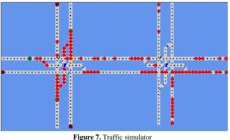
Currently, we are preparing to verify for the performance of the proposed scheme by using a traffic simulator. Fig.4 shows a screen shot of the simulator under construction. This is a simple cellular automata model with right turn lane. But it is expected to exhibit some important properties of traffic congestions such as a blocked phenomenon by a right turn traffic.
There are some user-defined non-trivial parameters in this method, and the sensitivity of the performance to these parameters should be investigated. Most influential parameters will be the set of actions. How much the degree of fluctuation should be is a rather intuitive factor. However, there is no way to explicitly know the true value of the turning ratio, unless tracking every vehicle’s travelling route at every junction, which is too much costly. Therefore, this method provides at least one of the ways to estimate the values by observation.
VII. CONCLUSIONS
This paper proposed a machine learning approach to improve the model parameters of the feedback control of an urban transit network. The proposed method is to provide estimation of turning ratio that is not obtained from real-time sensor measurement. An estimation method by RL is suitable for this purpose since the result of choosing a candidate of the parameter is measurable in real time. We will continue to verify the performance of the proposed method through simulations.
The feedback method on which this paper is relying is not considering cycle time and offset control. Including these controls will be highly complex problem, and a stochastic combinatorial approach like this paper seems to be one of the promising ways for further investigation.
Figure 6. Links corresponding to a turn rate
REFERENCES
[1] C. Diakaki, M. Papageorgiou and K. Aboudolas, “A multivariable regulator approach to traffic-responsive network-wide signal control”,
Control Engineering Practice, vol. 10, No. 2, p. 183-195, Feb. 2002.
[2] Y. Wakasa, K. Iwaoka, K. Hanaoka and K. Tanaka, “A Control Engineering Approach to Real-Time and Network-Wide Traffic Signal Control”, Transactions of the Society of Instrument and Control
Engineers, vol. 42, No. 9, p. 1076-1082, Sep. 2006. (in Japanese)
[3] P. B. Hunt, D. I. Robertson, R. D. Bretherton and M. C. Royle, “The SCOOT on-line Traffic Signal Optimisation Technique”, Traffic
Engineering and Control, Vol. 23, No. 4, p. 190-192, Apr. 1982.
[4] P. R. Lowrie, “SCATS: The Sydney Co-ordinated Adaptive Traffic System – Principles, Methodology, Algorithms”, Proceedings of the IEE
International Conference on Road Traffic Signalling, p. 67-70, 1982.
[5] Y. Sugiyama, “Physics of Traffic Flow”, Nagare : The Japan Society of
Fluid Mechanics, vol. 22, No. 2, p. 95-108, Apr. 2003. (in Japanese)
[6] R. S. Sutton and A. G. Barto, “Reinforcement Learning: An Introduction”, The MIT Press, 1998.
[7] M. Bando, K. Hasebe, A. Nakayama, A. Shibata and Y. Sugiyama, “Dynamical model of traffic congestion and numerical simulation”,
Physical Review E, vol. 51, No. 2, p. 1035-1042, Feb. 1995.
[8] M. Bando, K. Hasebe, K. Nakanishi, A. Nakayama, A. Shibata and Y. Sugiyama, “Phenomenological Study of Dynamical Model of Traffic Flow”, Journal de Physique I, vol. 5, No. 11, p. 1389-1399, Nov. 1995. [9] S. Lämmer and D. Helbing, “Self-control of traffic lights and vehicle
flows in urban road networks”, Journal of Statistical Mechanics: Theory
and Experiment, vol. 2008, No. 4, p. P04019, Apr. 2008.
[10] S. Mimura and M. Hisai, “Construction of Real-Time Control Logic for Signalized Network Under Over-Saturated Condition”, Memoirs of the
Faculty of Engineering Yamaguchi University, vol. 57, No. 1, p. 15-19,
Oct. 2006. (in Japanese)
[11] H. Ishikawa, H.Shimizu, Y. Sobata and M. Kobayashi, “Congestion Length Control for a Traffic Network”, IPSJ journal, vol. 45, No. 4, p. 1154-1162, Apr. 2004. (in Japanese)