Wall―
Jet a10ng a Circular Cyhnder in
Uniforュ
n Flow―
its inixing region一
by
Fumio YosHINO*and Ryoii WAKA* (Rece ed May l,197の
There is Presented the half of the investigation that had been carried out on the velocity distribution of the jet around and the aerodynamic force acting on
a circular cylinder with tangential injection of air,It、 vas Found that separation bubble is formed at the point of discontinuity of the curvature of the wall and the differential equation of the thickness of jet can accurately predict the real
thickness.
l lntroductio■
It has been、vell kno、vn for a 19ng tiine that the jet flows along the cylinder surface、vhen it is injected to the tangential direction on the circular cylinder. This is the so‐ called Cるanda effect. A number of investigationsり 、vere carried out
under the condition that the air is iniected but the main flo、、/does not exist. There
is only a few cases in which the velocity distribution of the flo、 v is meastlred when
the main flow exists,ho、 vev er, On the other hand,Inaking use of the Coanda effect, we can control the boundary layer and obtain the high lift on a circular cylinder.
Dunhan12)and others carried Out an investigation on this subject. But, we can
hardly find the detailed investigation in which the position of the slot is extensi‐ vely varied at a small value Of CFt. In this report, we carried out the experiinent
more systematically to get the velocity distribution in the mixing region of the flo、v when the position of the siot and the strength of the injection are varied at
rather small Reynolds Number, while t、 vo dirnensionality of the flo、 v being caref‐
ully kept.
買
&B
2 Nomenclature
: Radius and span of the circular cylinder
i WVidth of the slot
: 正)istance froal the center of the span in the spanwise direction (starbO_ a
S Z
RoPortS Of the Fac、 llty of Engnieering, Tottori University, Vol. 4 No, 1
ard is plus)
: Distance froHi the、vall in the radial direction
:夕 at
π
=ク″and%=(″ ″
+し「
)/2 respectively Thickness of the H xing regiOn of the jetAngle measured clockwise from the leading edge( Fig。 1(a)) Angle between the top of the cylinder and the slot(Fig。 1(a))
Angle measured clockwise from the slot(=θ
―
(浮年 十 θ
ァ
))(=為
・
?)
Velocity in the direction of θ at the pointノ
laxilnum velocity in the cross― section of the jet
Velocity at the outer edge of the jet Velocity ratio(= 1//%″ )
Static pressure in the test section of the、 vind tunnel Static pressure on the circular cylinder
Pressure of the compressed air inside the circular cylinder
Momentum coefficient(″
ο
ttι″
%物げ 膨ι″サ″ チ
カ
ι
S乃サι
打
″×
s)/(p∞ ytt R)Wind tunnel velocity
Reynolds Number(=
Reynolds Number(=
Kinematic viscosity
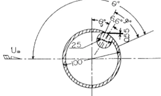
Fig. 1(a)CrOSS‐Section Of the circular cyユ ー ■4der. ″ , y ノ ノ う θ θ
&ノ
ガ2 ψ ク %″ 」 η P∞ 島 P″ ● y∞ RοヵF R。″ ν ((P″ ―P∞)RS/pν2)1/2)2y∞
買/フ )3 Experimental
3‐l Experimental installment
Fig。 1(a)ShOWS the cross― section of the model cylinder used in the experilnent.
The small cylinder, 25■ lln in diameter, is inscribed to the large pipe of 1001nm in
diameter and this small pipe makes a part of the nozzle wa11. The iet iS injected
along the circular cylinder from the slot,
This s10t has a constant width of O。
55 + I:1栃:nam oVer the、vhole span. Stays are
equally spaced at four points to keep the
slot width constant.
The circular cylinder can be rotated cir―
cumferencially, so that the slot can be
fixed at any position. The outside of the model cylinder is made into a n rror‐like
surface by chrome― plating. This modle
cylinder has 100mm outer diameter, 404mm
42 F■ mio YOSHINO and RyojI VAKA:Wall―
Jet along a Circular Cylinder in a UnifOrm Flow――its mixing region―spanwise width, and 35 static‐pressure holes are made on the circumference at the
Center Of the span. Inside of the model, 5 holes are arranged as equally as possible to measure the pressure inside of the cylinder.
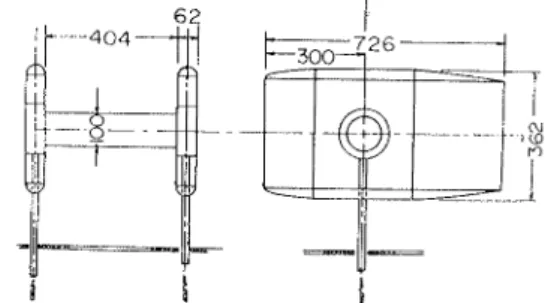
Fig。 1(bl ShOヽVS the assembly dra、 ving of the cylinder fixed on the three‐
compOnent
balance. The end plates with aerofoil sect‐ ion are installed at bOth ends of the cyli‐
ner。「Γhese dimensions are 62mm thick, 762
m■1 10ng and 362■lin high.
The struts are connected 、vith the cylin‐
der inside the end plates and they are
fixed On the three―component balance afterpassing through the bottOni of the end
plates and thrOugh the f100r Of the 、vind
tunnel. The strut is honow, so that the
compressed air is supplied from both sides Of the balance to the inside of the cyl―
inder through flexible tubes made of cioth, through a stop valve and then through the inside of the strut,
The、 vind tunne13)uSed for the experilnent is Goettingen type. frhe test section of the、 vind tunnel has the cross‐ section of l.0×
0,7m and its length is l.5m. The
maxil■u■l tunnel speed is measured about 52m/s and the ratio of the nOzzle contr‐action is 6.
In order to measure the velocity distribution, a total head pitOt tube 、
vas made
by for■ling the cross‐sectiOn Of the tip of wire for a hypoder“lic needle into rectan‐gle. This pitot tube is fixed on the H crometer and then this ■licrometer is attac‐ hed tO the circular‐ arc hoiding plate with the aerofoil section.
3…
2 Experimental method
We carried out t、vo kintt of measurement to check the velocity distributiono One is the case of iniecting the jet only (Ⅵ rithヽVind off)ヽ Vithout the main flo、v and the
other is the case of having both of the jet and the main flow. ヽ
Ve measured the
velocity distribution at many points along the flo、 v direction mainly in the center section of the span. At the same tilne, 、ve took lneasurements at several points in the spanwise direction to check the two dilnensionaHty of jet.
In case of iet only, the s10t position is fixed at θデ= 0°
, and the measurement
was carried out as in the fono、ving three cases, Reynolds Number Rのげ=1.61×10⁴ , 3.49×10⁴ and 8.11× 10⁴ . In this case, the atomospheric pressure is used as the ref‐ erence static pressure to calculate velocity. We also took three sorts of measureme‐nts when the main flow exists.Here,the slot position is fixed at θ′=0° and Crz is
O.085, 0.313 and O.544, Reynolds Number R。 ″ = 3.2 x 10S , We used the static pre‐ Fig。 1(")CirCular cylinder with end,lates
Roports of the Faculty of Engineering, Tottori University, Vol,4 No. 1
ssure of the wall obtained in the center section as the reference static pressure to get the velocity, We corrected the error due to compressibility by the calculation4) when velocity is high.
4 Results
4‐
l The case without the main flow
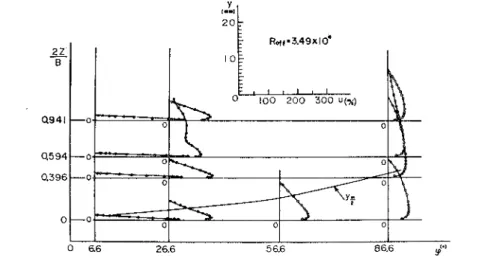
Fig, 2 sho、vs the velocity distribution at various points in both span、
7iSe and
flow directions, 、vhen R。」げ= 3.49x10⁴ . In this case, it is seen that the flow is approximately t、 vo diinel■sional in full length of the span, excluding distortion of the velocity distribution near the outer edge of the profile at the position of 2Z7B= 0.594 and ? = 26.6° .
Fig。 2 Velocity distribut二on at various Positions without main fiow.
Fig。 3(a)shOヽVS the velocity distribution of the ■1ユ
xing region of iet at fOur
spanwise sections at 夕=6.6°. Fig, 3(b)shOWS the velocity distribution at the same
span、vise sections, but at? = 86.6° . It iS
obvious that the velocity profile is similar
in the spanlvise direction、 vhen the position in the flow direction is same.
Tables l and II show the follo、 ving ratios ノ″力 筋じ,ノ
も■り1粋f andク″/%″ σ
at he three
points of the flow direction, where ノ″ is the thickness of the boundary layer,,上
thickness of the jet andク
″
maxiinuni vel‐ocity in the velocity profile.ノ
″
r,ノ考
・
and
自 ” ︱ ” 日 牌 ︲︱ 皓 悌 2 . Rc″ =3.49×10⁴ 作 66° R off ==3.49× 10⁴ ?=86.6° SymbOls 2z/B 0 0 0 0 149 Δ O.396 X O,941 ヽ 10%ゎlAl lbl
Fig。 3 velocity distJibutions of the ttlixing
fl詩In at various positions without main
44 Fumio YOSHINO and Ryoji WAKA:Wan―
Jet along a Circular Cylinder in a Uniform Flow――its mixing region一Table. I The values oF,″ /ノ/1P,(ケ
1争/ノ七升θ ), Roυげ=3.49×10⁴
殺
O
O乙96
0594
O.94166
蝸
°
・
91ttD
°ヽ ,93WII⑥
26.C 1・OIVOOl墳
1.10
I.ZIrスら6
O O レ 8 f 86.C比
Ч
Vo⑥
I・(i571
韻耳
.│⊃ Iυ倦
8つTable. I The values of″
"/″″。すRωげ=3.49× 104
殺
0
0396
0594
Q941
6.6 │,00 │.12 │.03Q98
2∝
│.OO │.01 α75
│.08 86.6 │.00Q87
O.810,85
夕,ヵ略σ are the values in the center section.
Fro■l these tables, it comes out that the relative discrepancy to each other of
the boundary layer thickness, iet thickness and the maxilnum velocity in the secti‐
on is small in comparison with the span 、vidth, excluding the distortion of the
above mentioned velocity distribution. Therefore, taking Fig。 3 into consideration,
the jet is nealy two dil■ensional. The above mentioned fact is noticed in case of two other R。 ガs as we■.
Fig. 4 shows the velocity distribution at various points in the flow direction at the
center sectiOn of the span, This figure
sho、vs that the velocity at largerノ is sma‐
1ler than the velocity at other points, as
far as the velocity distribution at 9=86.6°
ls concerned.
Considering that we measured the very
slo、v motion by a pitot tube, the error is
to be great there.
Froni these facts, it is clear that the velocity distribution of the iet in our exp― erilnent is silnilar through the f10w direct‐ ion. The figure sho、 vs that the ratio of ノ″
力孝 iS almost constant, 0,2 in the flow
direction.Then Fig. 5 sho、 vs the static pressure
o 86.6
distribution on the wall in the flow direction. The full line in the figure is the experiェnental curve by Newlnan3). our pressure coefficient apprOaches O earlier
than Ne、vman's. The figure indicates that our separation point is located near 9s夕 ´
奮190°, and Ne、7man'S is backward by about 30°.
Fig.6 shows the experimental ratioノ
孝/Rψ t° ノ孝/R・ The relation atノ考
/買
>
0.C18 (9> 26.6° )is shOWn linear and it is expressed as fOno、 vs;Roff=3,49xt04
SymbOIs
ゴ°)。
6.6
●26.6
×56.6
Fig。 4 Velocity distributiOns in the flow
direction without main flow. る准 X た。 一 。 咲 o‘
05
L ︵ ︶ ORoPortS Of the Faculty of Engineering, Tottori University,Vol。 4 No. 1 Symbols 覧 II刑 ざ 諮 I SyttbdS
a49 0011
・ 酔 lxIざ 詭 乙49
″ │.61 ″ ∂∫ ,_メ S/R=OO15堺Ψ
=釦峰
(け24孫
)100 200 500
Ol02 0.5 04第
Fig.5 Static‐pressure distributions at the central section of the sPan without=nain fiow.
Fig.6 GrOwth of the jet in flow direction,
ノ
"
ノ″子
=ε
(1+々
千 )、There θ = 0,115 and力 = 2.4. These are a little larger than Newinan's values θ
=
0.1l and々 = 1.5。4‐2 The case with the rrlain flow
To deterHline parameter Cr, We used the iet Ve10city at the slot exit calculated
fro■l the air pressure and temperature inside the cyhnder. Fig. 7 shoヽ vs the veloc‐ ity distributions at various sections and points in the f10w direction when Cμ
=
0,313. This figure shows clearly that the velocity reduces earlier very near the end
plates than at other sections. This kind of things did not occur without the main
O 0 6 6 2.O to O― ‘ ♂ NewmOn o実重 Roff=548x104 L:_ 10861176
46 Fumio YOSHINO and Ryoji WAKA:wall―
Jet along a Circular Cylinder in a Uniform Flow一―its mixing region―flow. On the other hand, the velocity distribution is approxll■ately t、vo diinensional
near the center section of the span. But three dilnensionality seems to appear near the separation point.
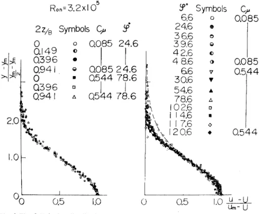
Fig.8 is the velocity distribution in the■ xing region at various sections in the
spanwise direction where Crz= 0,085, 夕 = 24.6° and Cμ
=0.544 and?=78.6° .Very
near the end plates, the velocity distribution shows that the velocity tends to get
a little bigger at largerノ than at other span sectiOns. But this tendency is very
small and the velocity distribution in the,lixing regiOn is approxilnately siinilar
allnost all over the span.
蝉帥一
︲︲
︲︲
︲]
Ю 冊 sections σig.Ron=5.2x10⁵
2z/8 SymbOL(》
♂
′
866
246
36.6
59.6
42.6
48.6
66
5α
6
546
78.6
026
146
1■6
2Q6
SymbO烙
O ● 0 O O 0 7 ▼ ▲ △ ロ 日 ◇ ◆働
Q085
a149
Q396
o941
O
Q396
Q941
O085 24.6
018521.6
露
,,手
:│:
O O ● 0 ロ ロ △ ヽ もO
▼
O Q5 10 0 o5
Fig.8 Fig.9 velocity distributio4S of the m二 xing region at various 8)and at Various points in flow direction (Fig。 9).
Tables III and IV correspond respectively to Tables l and II which are for the case、vithout the main flo、v. In this case, Cμ
= 0,313 and the separation point in
the center section is ヮs♂夕 = 89,6°. Table IV indicates that the velocity reduces ra‐pidly near the end plates, and the adverse flo、v is Obviously seen at a smaller ?
there than at the center section of the span.
Table III shows ttμ andノ生 thiCken early near the end plates. This corresponds
to the result of Table IV. Excluding the flo、v near the separation point, however, the ratios Ofノ
Roports ot the Faculty of Engineering,Tottori University,VoI.4 No.1 47
漁
―q149
O α396
q941
願 αrO_920)
846
I.OOO(1.OOO) 2.387ri xx∩lI.I03 F∩Cj46Ⅲ 2■6 驚 課 罪 6)
IPttω
α975
(1.OOけ '851.563)4a6
α808
fO_905〕 I.OOOri∩ oo】 αrO_842〕
807
αr∩528
907)6Q6
4 7 6 9 封 3 白 if名私。
3 1=台 RCLl銘離ヵ
8■G 4 1 2 う p 臼 2 pOO l_O O Ol0764
(O_737) 10働6 )OOヽ000) α(α831
963
激
―O.149 O α396
α941 Q6 I.OII i.OOO l.051 I.046 2■6 1.O08 1.OOO I.025 I.02148,C
Q979
I.OOO I.035 O.85666.G
Q957
LOOO
│.021 O.625 8■6 α681 I.OOO Io022-0.327
IOa6 │。
OOO
I.012 ―O.534_諺
2(α
88x枡
} う と (3) 1 一 2 〓和一榊
TaЫ∝ Ⅲ The vЛues ofプ″/勒″ギ考
/娑 ),TaЫ
α島 ,h≧ゞ】受二0::ク
″/ク″うゆ
=は
085 Cμ =0,085 and F。 ″=.2×105.section of the span, Taking the result of Fig. 8 into account,`
it can be said the
flow near the center section of the span is allnost two diinensional. But very near the separation point and the end plates, the flo、 v is three dilnensional. This is the point different frdtt the case of the iet、Vitllout the main flow.Fig, 9 shows the velocity distribution of the H xing region at the center section
of the span, This distribution is measured at various positions in the flo、 7 direC‐
tion. The figure shows two cases where Cμ = 0.085 and O.544. FroHl this figure, we find the velocity distribution in the ■lixing region is similar irrespective of the value of Cμ and the position of the flow direction. rrhe fact that the separation point of 9dヮター 96.6°, when Cμ = 0.544, shows that the velocity distribution keeps
si■11larity even after passing the separation point.
The broken line in the figure shows the hyperbolic function expressed by
"―
y
π″ ―
y
The full line shows the cosine function,
―
ω∫
π
―
ど
2-二毛
│と聖
生
―
)The full line has a good agreement、 vith the experiinent compared with the broken
line, although this cosine curve slightly underestilnates the velocity at largerノ・
That is, the velocity distribution in the ■
1lxing region can be expressed by the
equation (3), ヽVhen there is the main flo、v.Fumio YOSHINO and Ryoji WAKA:Wan―
Jet along a Circular Cylinderin a Uniだorm Flow一its mixing region―
direction at the center section of the span.
From Fig。 10, it is kno、vn that the thickn‐
ess of the jet y坐 /R increases correspondi‐
ngly to the increase of the thickness of the
boundary layer. Fig,10 shows,in this case, that the value ofタ タι does not become l until
it reaches the separation point, and after
separation, it approaches i rapidly.
ゴ°'
Fig. 10 variations ofプ ″/買 andノ野 資 ″ ●)in the flow direction.
5 Discusslo■
5‐
l The case without the main flow
CaJ and
As、ve mentioned before, in this experiinent the ratio of the thickness of iet to
the hickness of the boundary layer,ノ
"ヵ考 iS about O.2 and this is larger than the value of Ne■vlnan's experilnent O.14. In our experilnent, the separation point isヮ soψ
= 190°, but Newlnan's is a about 220° . FurthermOre, the constants in the equation (1), θ andl力 are a little bit larger than Newman's, These mean that the iet thickn‐ ess in our experilnent grows relatively rapidly.According to Newman,ノ ″/ヶ生,θ and
力become larger、
vhen Reynolds Number, R9ゎ
gets sma1ler than 4x 10⁴ and the se‐ paration point lnoves for、 vard. As shown in Fig. 5, Reynolds Number of the exper‐iment is nearly same, so we do not consider that the value of F9″ caused to thicken
the iet thickness, On the other hand, according to Fernholz6), when the ratio of
the slot width to the cyhnder radius s/R is Within the limit of O.053:≧ s/買
≧
0.0074,the separation point of the flow is same as far as compared by the same value of Rの力r and the velocity distribution of the part of boundary layer, in case of turbul‐
ent flo、v forms the Glauert7)'s turbulent velocity distribution of the wall jet along the plate. It seems to be unreasonable to attribute it to the slot、 vidth, because of
S/R = 0,01l in our experilnent, Assunling that the jet injected frori the slot is an inviscid fluid and it flows along the、vall keeping its thickness equal to the slot
width, we can have the following equation(4)6), if it is incompressible fluid,
斗
斗
Roports of the Faculty of Engineering, Tottori University, Vol. 4 No. 1
十
(In this experilnent, the iet iniected from the slot flows first along the small
cylinder with the diameter of 25141n, and second it flo、 vs along the larger cylinder with the diameter of 100■lln after passing the contact point of the small cylinder 、vith the main cylinder.s/R varies discontinuously froln O,044 to O.01l before and after this contact point. In such the floコ r, the static pressure rises discontinuously fron1 0.09 to O.022 before and after the contact point, Or the ratio of(IP∞ ―
Ps)R/
(P″ 一P∞
)S goeS up discontinuously from 8.2 to 2 before and after the contact
point, where R=50nll■ . But the above assumption does not come into existence inthe real flow. Therefore, the pressure rise will not occur so rapidly.
From Fig. 5, the static pressure bet、veen the contact point of the cylinders (9 = 6.6°)and 10° dO、vn strean■ is nearly constant and the value is about 4. The rapid
rise of the pressure takes placeゎ etヽVeen 10° and 20° , and then at 20°
the pressure
becomes around O.5,After that, the pressure goes down to about l,25 and remains at this value. For about 10 degrees after the contact point, pressure is kept relativ‐
ely lo、
v. This resembles the pressure of the separation bubble near the leading
edge of the aerOfoil, so it appears to be the separation of la■ linar flow but it canbe turbulent fk)、v since the value ofノ″ψ/ ク″/〃 8)is larger than 9 near the contact
pointo We can only consider discontinuity of the radius of curvature makes bound― ary layer thicker and its turbulence stronger. We may conclude that the turbulence of our iet is intensive, the ratio r/″ /,生 getS bigger, the thickness of the iet grOws
relatively rapidly and the separation point moves forward o、 ving to this reason.
5‐
2 The case with the main flow
As lnentioned before, the velocity distribution in the ■lixing region is siinilar
until it passes the separation point in case with the main flow and the profile is approximated by the equation(3). ThiS Silnilarity is independent of CP as far as this experilment goes,
When the velocity distribution is silnilar, the iet thiCkness is the function of the central angle n″ 、vhiCh iS measured froEl the Slot and the velocity ratioタ タタ
(=
3■%か。 Then the foHowing equation9) is derived, P∞ ― Ps Pω ― P∞ )2 θ (1-解 ) 1-θ力ψ
+η
(1+じ力ψ) (4) S 一 翌 S 一 R 2 〓幹
=下
満 焔 斗
+
(R+カ
ノ望) (5)
In the above equation, どand力 are identical with θ and力 of the equation (1)and ητ
= 0.5 when解
≧0.5.50 Fumio YOSHINO and Ryoji vAKA:Wall―
Jet a10ng a Circular Cylinder in a UnifOrm Flow― ―its mixing region一tiOn(5)Inaking use Of a computer,where the experilnental valuc Ofノ
″ (Fig。 10(a))
and ηι = o.5 were used. In Fig。 10(b), up until the separatiOn pOint η夕≧ 0.5 so that η夕 = o.5, the initial value Ofノ 聖L iS taken as the value at the intersectiOn Of the extensiOn of the curve which smoOthly cOnnects the expdrimental points(Fig. 101a))with the straight lineヮ = 0。. The thick fun line in Fig. 10(a)shOWS the result Of the calculation in which we used the constants θ = o.115, and力
= 2.4
(Fig. 6)of our jet and the broken line is the case by the constants of Newman
and others, that is θ = o.1l and力 = 1.5,
As the figure shO、 vs clearly, the value obtained by calculatiOn seems tO be、 vithin the experiinental error near the s10t with either cOnstants, The c10ser it gOtS tO the separatiOn point, hO、vever, the better the value calculated with Our values of ι = 0,115 and力 = 2.4 agrees Mrith the experil■ental value.
ヽVe already discussed、vhy Our θ
and
々are different from thOse of Newman's.
When there is the main flo、 v, the influence Of the foliowlng factors shOuld be taken into accOunti the bOundary layer thickness Of the main f10w upstreaHl of the slot,
the shape and thickness Of the upper lip. But 、
ve consider these effects can be
ignored due tO the next reasons. That is, the influence Of the bOundary layer thic‐
kness seems nOt tO be dependent on models, since the boundary layerヽ thickness Of the upstrean■ is deter“lined by Reyコoldsユ Чumber only if the、vall is hydrodyna■
lic‐
ally smooth. The influence Of the upper‐ lip thickness of the s10t can not be discu―
ssed directly, becanse there dO not see■ l tO exist Other measurements of the ve10city
profile of jet with the main f10、
v around a circular cylinder, According to the
experilnents10)11)on the effectiveness Of filln cooling Over the flat plate, when夕 % ■ l and the thickness Of the upper lip is thick compared 、vith the siOt width, the 、パrake of the upper lip gets larger, the turbulence strOnger, and then the effectiv―
eness is reduced, When″ ″2 > 1, the iet is pulled a、
vay off the
、vall tO the main
flow and the separatiOn bubble appears right after the siOt exiti2). The effective‐
ness approaches a certain constant, however, 、vhen the upper‐ lip thickness is thin enough in comparisOn、 vith the sIOt 、vidth s and its ratiO is smaller than O.38.
When″
2夕 ≦ζl, the separatiOn bubble disappearsiO).This seems qualitatively true about the iet arOund the circular cylinder, too, SO,
the influence Of the upper lip Of the slot On the turbulence Of the jet seems able
to be ignored, if the upper lip Of the s10t is thin enough and″ ″ ≦ 1. In Our case,
the ratiO Of the upper― lip thickness to the s10t、vidth is about O.2 and the upper lip is thinned to the tlp so that the influence of the upper lip can be ignOred, The
wake of the upper lip is not seen in Fig. 7 even at right after the s10t. This also true for the other values Of c//.
Fro■l the facts mentiOned above, it may be concluded that the curvature of the
wall varied discontinuously at right after the slot results ln that the values of θ
RopOrts of the Faculty of Engineering, TOttori University,Vol.4 No. 1 51
man. This, in turn, lneans thatノ 牲can be calculated froni the equation(5)by using the values for θ
and々
given by Ne、 vman, if the iet iS iniected tangentially to thecircular cylinder which has a constant curvature and the upper lip of the slot is
thin enough.
The structure of the slot used by Newman, however, can not give us a good cir―
cularity, lrherefOre, it is more convenient to make use of the structure of our slot
than Newlnan's in order to analyze the over‐ all flow around the cylinder, since our slot guarantees the good circularity. Of course, it must be kept in■lind that,
the values of O,115 and 2.4 for θ
and
力 respectively are used in the equation(5) 、vhen the slot is designed based on ours.6 Conclusion
(1)The case without the main flow.
(I) There exists a large negative pressure right after the slot exit. This
takes place due to dlscontinuous increase of the radius of curvature of
the wall where the jet flows along.
(II) frherhfore, the iet thiCkness grows a little carlier than Newmsn's experi‐
ment.
(2)The caSe with the main flow.
(I) A large negative pressure exists right after the slot exit due to the same
reason as the case、vithout the main flo、
v. This is a local phenomenon,
however,
(II) The velocity distribution in the■ lixing region is silnilar as expressed by
the equation(3). And it is still siinilar after passing the separation point.
(III)Differential equation(5)iS made sure to hold.
References
(1)Wille,R and Fernholz,」 .,J.FIuid Mech.,28-4(196の ,801.
(2)Dunham,J.,Aeron.J.,74(1970-1),91・
(3) Yoshino and the other, Reports of the Faculty of Eng. Tottori Univ.,1-1(ShOWa 45-12),7.
(4)POtf,Method of Aerodynamic ExPettment in MechanicaI Engineering,(ShoWa 44), 136,
Asakura.
(5〕 Lachman■,G,V.(ed・ ),BOundary Layer and Flow Control,1,(1961),232,Pergamon.
(6)Feraholz,H.,Jahrbuch 1964 der私アGLR,149. (7)Glauert,M.B.,J.Tluid Mech.,(1956),625.
(3)SChliChting,H.,Boundary Layer Theory,(1960), 36,McCraw‐Hill,
(9) Yoshino and Furuya,Preprint of Bulletin of JSME, No.723-2(Showa47-の , 121. 16 Kacker,S.C.and Whitelaw,J,H,Trans.ASME,Ser,C,90-4(1968-11),469.
52 Funio YOSEINO and Ryoji wAKA:再
∼
「an‐ Jet i,1。ng a Circular Cylinder
in a U4f。 ■
m Fiow―
iぃ m ingresi04-&9 Buratt w.K.and St01lery,J.L.,Int.J.Heat tt Mass TFanSt`,12(1969-11).985.